| Skip Navigation Links | |
| Exit Print View | |

|
Sun Fire X4640 Server Service Manual Sun Fire X4640 Server Documentation Library |
| Skip Navigation Links | |
| Exit Print View | |

|
Sun Fire X4640 Server Service Manual Sun Fire X4640 Server Documentation Library |
About This Documentation (PDF and HTML)
Sun Fire X4640 Server Service Manual Overview
Controlling Power and Performing Hardware Reset
Powering the Server On and Off
Controlling Server Power Remotely
Resetting the Server Using the Reset Switch (SW2)
Removing and Installing Components
Antistatic Procedures and Precautions
Tools Required for Servicing the Sun Fire X4640 Server
Preparing the Server for Service and Operation
Removal and Replacement Procedures
List of Customer Replaceable Units and Field Replaceable Units
Replacing the CMOS Battery (CRU)
Replacing or Adding a Hard Drive (CRU)
Replacing a CPU Module and Filler Card (CRU)
Replacing or Adding DIMMs (CRU)
Replacing or Adding PCI Cards (CRU)
Replacing or Adding a Power Supply (CRU)
Replacing the Service Processor Board (FRU)
Replacing the DVD Module (FRU)
Replacing the Power Distribution Board (FRU)
How to Remove the Power Distribution Board
Bus Bar to DIMM Clearance Verification
Replacing the Fan Tray Carriage (FRU)
Replacing the Front Panel Indicator Board (FRU)
Replacing the Front I/O Board (FRU)
Replacing a Hard Disk Backplane (FRU)
Replacing the Motherboard (FRU)
Updating Field-Replaceable Unit Information
How to Update the Server CPLDs
Configuring the System Using the BIOS Setup Utilities
BIOS and the BIOS Setup Utility
How to Configure the System BIOS
BIOS and Service Processor Updates
LSI BIOS Configuration Utility
Sun Fire X4640 Server References and Specifications
Sun Fire X4640 Server Features and Components
Sun Fire X4640 Server Front and Back Panel Features and Components
Sun Fire X4640 Server Specifications
Sun Fire X4640 Server Motherboard Jumpers and Switches
Sun Fire X4640 Server External LED Locations and Meanings
Note - Do not torque the nuts to specification, yet.
Do not loosen the lower (positive) bus-bar nut.
Make note of the CPU module and filler card positions, so you can return them to their original slots.
This action removes the flex from the bus bar ensuring that the bus bar lies flat against the chassis midwall.
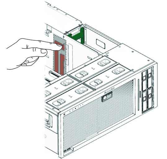
Note - The bus bars might be covered with a mylar insulation. Do not remove the insulation. The insulation protects the DIMMs on the CPU module in slot A.
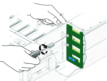
The DIMMs must not contact the insulation on the bus bars.
