Installing the Hardware
Perform the following procedures to connect the cluster hardware components. See your hardware documentation for additional information and instructions.
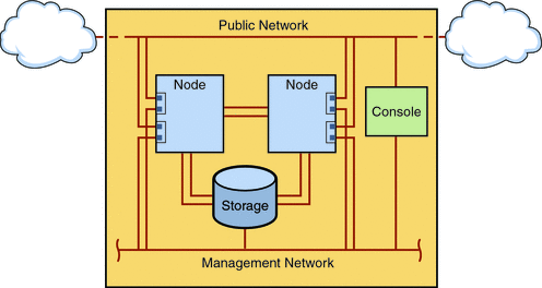
The following figure illustrates the cabling scheme for this configuration.
Figure 1–1 Cluster Topology and Cable Connections

 How to Connect the Administrative Console
For ease of installation, these example installation procedures apply to using an administrative console that is installed with Cluster Control Panel software. However, Sun Cluster software does not require that you use an administrative console. You can use other means to contact the cluster nodes, such as by using the telnet command to connect through the public network. Also, an administrative console does not have to be dedicated exclusively to use by a single cluster.
-
Connect the administrative console to a management network that is connected to phys-sun and to phys-moon.
 How to Connect the Cluster Nodes
-
As the following figure shows, connect ce0 and ce9 on phys-sun to ce0 and ce9 on phys-moon by using switches.
This connection forms the private interconnect.
Figure 1–2 Two-Node Cluster Interconnect

The use of switches in a two-node cluster permits ease of expansion if you decide to add more nodes to the cluster.
-
On each cluster node, connect from ce1 and ce5 to the public-network subnet.
-
On each cluster node, connect from ce2 and ce6 to the management network subnet.
 How to Connect the Sun StorEdge 3510 FC RAID Array
-
Connect the storage array to the management network.
Alternatively, connect the storage array by serial cable directly to the administrative console.
-
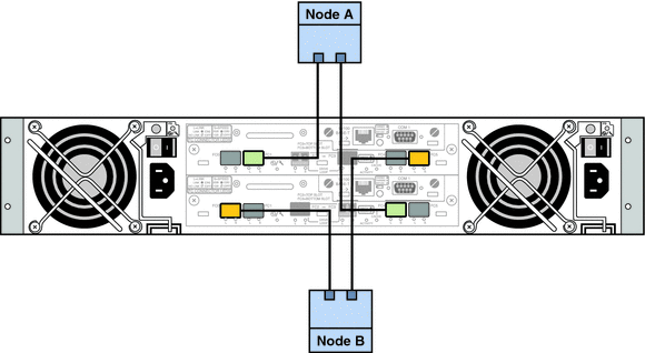
As the following figure shows, use fiber-optic cables to connect the storage array to the cluster nodes, two connections for each cluster node.
One node connects to a port on host channels 0 and 5. The other node connects to a port on host channels 1 and 4.
Figure 1–3 Sun StorEdge 3510 FC RAID Array Connection to Two Nodes

-
Power on the storage array and check LEDs.
Verify that all components are powered on and functional. Follow procedures in First-Time Configuration for SCSI Arrays in Sun StorEdge 3000 Family Installation, Operation, and Service Manual, Sun StorEdge 3510 FC Array.
 How to Configure the Storage Array
Follow procedures in the Sun StorEdge 3000 Family RAID Firmware 4.2 User’s Guide to configure the storage array. Configure the array to the following specifications.
-
Create one global hot-spare drive from the unused physical drive.
-
Create two RAID-5 logical drives.
-
For redundancy, distribute the physical drives that you choose for each logical drive over separate channels.
-
Add six physical drives to one logical drive and assign the logical drive to the primary controller of the storage array, ports 0 and 5.
-
Add five physical drives to the other logical drive and assign the logical drive to the secondary controller, ports 1 and 4.
-
-
Partition the logical drives to achieve three partitions.
-
Allocate the entire six-drive logical drive to a single partition.
This partition will be for use by Sun Cluster HA for Oracle.
-
Create two partitions on the five-drive logical drive.
-
Allocate 40% of space on the logical drive to one partition for use by Sun Cluster HA for NFS.
-
Allocate 10% of space on the logical drive to the second partition for use by Sun Cluster HA for Apache.
-
Leave 50% of space on the logical drive unallocated, for other use as needed.
-
-
-
Map each logical drive partition to a host logical unit number (LUN).
Partition Use
LUN
Oracle
LUN0
NFS
LUN1
Apache
LUN2
-
Note the World Wide Name (WWN) for each LUN.
You use this information when you create the disk sets later in this manual.
- © 2010, Oracle Corporation and/or its affiliates
