Chapter 7 SPARC: Campus Clustering With Sun Cluster Software
In campus clustering, nodes or groups of nodes are located in separate rooms, sometimes several kilometers apart. In addition to providing the usual benefits of using a Sun cluster, properly designed campus clusters can generally survive the loss of any single room and continue to provide their services.
This chapter introduces the basic concepts of campus clustering and provides some configuration and setup examples. The following topics are covered:
This chapter does not attempt to explain clustering, provide information about clustering administration, or furnish details about hardware installation and configuration. For conceptual information about clustering, see your Sun Cluster concepts documentation and your Sun Cluster system administration documentation.
SPARC: Requirements for Designing a Campus Cluster
When designing your campus cluster, all the requirements for a noncampus cluster still apply. Plan your cluster to eliminate any single point of failure in nodes, cluster interconnect, data storage, and public network. Just as in the standard cluster, a campus cluster requires redundant connections and switches. Disk multipathing is useful to help ensure that each node can always access each shared storage device. These concerns are universal for Sun Cluster.
After you have a valid cluster plan, follow the remaining requirements in this section to ensure a proper campus cluster. To achieve maximum benefits from your campus cluster, consider implementing the SPARC: Guidelines for Designing a Campus Cluster.
SPARC: Selecting Networking Technologies
Your campus cluster must observe all requirements and limitations of the technologies you choose to use. SPARC: Determining Campus Cluster Interconnect Technologies provides a list of tested technologies and their known limitations.
When planning your cluster interconnect, remember that campus clustering requires redundant physical (not logical) network connections.
SPARC: Connecting to Storage
A campus cluster must include at least two rooms using two independent SANs to connect to the shared storage. See Figure 7–1 for an illustration of this configuration.
Additional rooms need not be fully connected to the shared storage. However, if you are using Oracle Real Application Clusters (RAC), all nodes which support Oracle RAC must be fully connected to the shared storage devices. See SPARC: Quorum in Clusters With Four Rooms or More for a description of a campus cluster with both direct and indirect storage connections.
SPARC: Sharing Data Storage
Your campus cluster must use SAN-supported storage devices for shared storage. When planning the cluster, ensure that it adheres to the SAN requirements for all storage connections. See the SAN Solutions documentation site for information on SAN requirements.
You must mirror a campus cluster's shared data. If one room of the cluster is lost, another room must be able to provide access to the data. Therefore, data replication between shared disks must always be performed across rooms, rather than within rooms. Both copies of the data should never be in a single room. Host-based mirroring is required for all campus cluster configurations, because hardware RAID alone does not lend itself to providing data redundancy across rooms.
In addition to mirroring your data, you can add storage-based data replication if you judge that your campus cluster needs the additional data redundancy. See Appendix A, Data Replication Approaches for more information on storage-based data replication.
SPARC: Complying With Quorum Device Requirements
You must use a quorum device for a two-node cluster. For larger clusters, a quorum device is optional. These are standard cluster requirements.
In addition, you can configure quorum devices to ensure that specific rooms can form a cluster in the event of a failure. For guidelines about where to locate your quorum device, see SPARC: Deciding How to Use Quorum Devices.
SPARC: Replicating Solaris Volume Manager Disksets
If you use Solstice DiskSuite/Solaris Volume Manager as your volume manager for shared device groups, carefully plan the distribution of your replicas. In two-room configurations, all disksets should be configured with an additional replica in the room that houses the cluster quorum device. For example, in three-room two-node configurations, a single room houses both the quorum device and at least one extra disk configured into each of the disksets. Each diskset should have extra replicas in the third room.
Note –
You can use a quorum disk for these replicas.
Refer to your Solstice DiskSuite/Solaris Volume Manager documentation for details on configuring diskset replicas.
SPARC: Guidelines for Designing a Campus Cluster
In planning a campus cluster, your goal is to build a cluster that can at least survive the loss of a room and continue to provide services. The concept of a room must shape your planning of redundant connectivity, storage replication, and quorum. Use the following guidelines to help you manage these design considerations.
SPARC: Determining the Number of Rooms in Your Cluster
The concept of a room, or location, adds a layer of complexity to the task of designing a campus cluster. Think of a room as a functionally independent hardware grouping, such as a node and its attendant storage or a quorum device physically separated from any nodes. Each room is separated from other rooms to increase the likelihood of failover and redundancy in case of accident or failure. The definition of a room therefore depends on the type of failure to safeguard against, as described in Table 7–1.
Table 7–1 SPARC: Definitions of “Room”|
Failure Scenario |
Sample Definitions of “Room” |
|---|---|
|
Power-line failure |
Isolated and independent power supplies |
|
Minor accidents, furniture collapse, water seepage |
Different parts of a physical room |
|
Small fire, fire sprinklers starting |
Different physical areas (for example, sprinkler zone) |
|
Structural failure, building-wide fire |
Different buildings |
|
Large-scale natural disaster (for example, earthquake or flood) |
Different corporate campuses up to several kilometers apart |
Your campus cluster can consist of two rooms, each containing a combination of one or more nodes and storage devices. However, a properly configured cluster with three or more rooms will be more resilient if a failure occurs.
Whenever a two-room campus cluster loses a room, it has only a 50 percent chance of remaining available. If the room with fewest quorum votes is the surviving room, the surviving nodes cannot form a cluster. In this case, your cluster requires manual intervention from your Sun service provider before it can become available.
The advantage of a three-room or larger cluster is that, if any one of the three rooms is lost, automatic failover can be achieved. Only a properly configured three-room or larger campus cluster can guarantee system availability if an entire room is lost (assuming no other failures).
Sun Cluster does support two-room campus clusters. These clusters are valid and might offer nominal insurance against disasters. However, consider adding a small third room, possibly even a secure closet or vault (with a separate power supply and proper cabling), to contain the quorum device or a third server.
SPARC: Three-Room Campus Cluster Examples
A three-room campus cluster configuration supports up to eight nodes. Three rooms enable you to arrange your nodes and quorum device so that your campus cluster can reliably survive the loss of a single room and still provide cluster services. The following example configurations all follow the campus cluster requirements and the design guidelines described in this chapter.
-
Figure 7–1 shows a three-room, two-node campus cluster. In this arrangement, two rooms each contain a single node and an equal number of disk arrays to mirror shared data. The third room contains at least one disk subsystem, attached to both nodes and configured with a quorum device.
-
Figure 7–2 shows an alternative three-room, two-node campus cluster.
-
Figure 7–3 shows a three-room, three-node cluster. In this arrangement, two rooms each contain one node and an equal number of disk arrays. The third room contains a small server, which eliminates the need for a storage array to be configured as a quorum device.
Note –
These examples illustrate general configurations and are not intended to indicate required or recommended setups. For simplicity, the diagrams and explanations concentrate only on features unique to understanding campus clustering. For example, public-network Ethernet connections are not shown.
Figure 7–1 SPARC: Basic Three-Room, Two-Node Campus Cluster Configuration With Multipathing
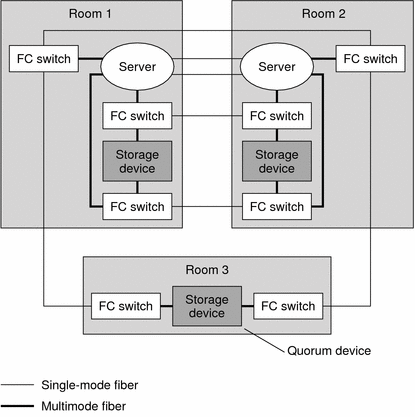
In the configuration shown in Figure 7–1, if at least two rooms are up and communicating, recovery is automatic. Only three-room or larger configurations can guarantee that the loss of any one room can be handled automatically. Loss of two rooms requires the replacement or rebuilding of one room and typically requires Sun service provider intervention.
Figure 7–2 SPARC: Minimum Three-Room, Two-Node Campus Cluster Configuration Without Multipathing
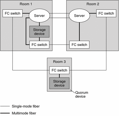
In the configuration shown in Figure 7–2, one room contains one node and shared storage. A second room contains a cluster node only. The third room contains shared storage only. A LUN or disk of the storage device in the third room is configured as a quorum device.
This configuration provides the reliability of a three-room cluster with minimum hardware requirements. This campus cluster can survive the loss of any single room without requiring manual intervention.
Figure 7–3 SPARC: Three-Room, Three-Node Campus Cluster Configuration
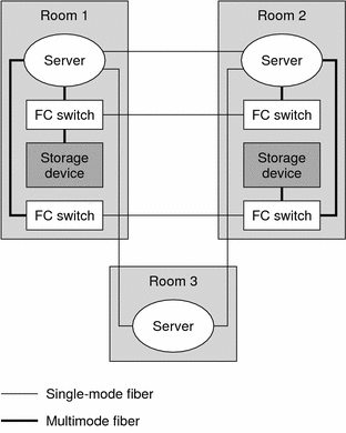
In the configuration shown in Figure 7–3, a server acts as the quorum vote in the third room. This server does not necessarily support data services. Instead, it replaces a storage device as the quorum device.
SPARC: Deciding How to Use Quorum Devices
When adding quorum devices to your campus cluster, your goal should be to balance the number of quorum votes in each room. No single room should have a much larger number of votes than the other rooms, because loss of that room can bring the entire cluster down.
For campus clusters with more than three rooms and three nodes, quorum devices are optional. Whether you use quorum devices in such a cluster, and where you place them, depends on your assessment of the following:
-
Your particular cluster topology
-
The specific characteristics of the rooms involved
-
Resiliency requirements for your cluster
As with two-room clusters, locate the quorum device in a room you determine is more likely to survive any failure scenario. Alternatively, you can locate the quorum device in a room that you want to form a cluster, in the event of a failure. Use your understanding of your particular cluster requirements to balance these two criteria.
-
For each room, total the quorum votes (nodes) for that room.
-
Define a quorum device in the room that contains the lowest number of votes and that contains a fully connected shared storage device.
Refer to your Sun Cluster concepts documentation for general information about quorum devices and how they affect clusters that experience failures. If you decide to use one or more quorum devices, consider the following recommended approach:
When your campus cluster contains more than two nodes, do not define a quorum device if each room contains the same number of nodes.
The following sections discuss quorum devices in various sizes of campus clusters.
SPARC: Quorum in Clusters With Four Rooms or More
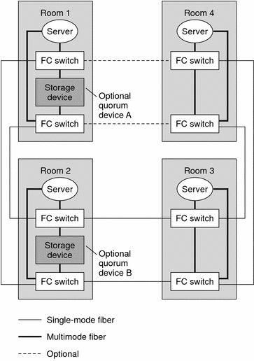
Figure 7–4 illustrates a four-node campus cluster with fully connected storage. Each node is in a separate room. Two rooms also contain the shared storage devices, with data mirrored between them.
Note that the quorum devices are marked optional in the illustration. This cluster does not require a quorum device. With no quorum devices, the cluster can still survive the loss of any single room.
Consider the effect of adding Quorum Device A. Because the cluster contains four nodes, each with a single quorum vote, the quorum device receives three votes. Four votes (one node and the quorum device, or all four nodes) are required to form the cluster. This configuration is not optimal, because the loss of Room 1 brings down the cluster. The cluster is not available after the loss of that single room.
If you then add Quorum Device B, both Room 1 and Room 2 have four votes. Six votes are required to form the cluster. This configuration is clearly better, as the cluster can survive the random loss of any single room.
Figure 7–4 SPARC: Four-Room, Four-Node Campus Cluster
Note –
In Figure 7–4, the cluster interconnect is not shown.
Consider the optional I/O connection between Room 1 and Room 4. Although fully connected storage is preferable for reasons of redundancy and reliability, fully redundant connections might not always be possible in campus clusters. Geography might not accommodate a particular connection, or the project's budget might not cover the additional fiber.
In such a case, you can design a campus cluster with indirect access between some nodes and the storage. In Figure 7–4, if the optional I/O connection is omitted, Node 4 must access the storage indirectly.
SPARC: Quorum in Three-Room Configurations
In three-room, two-node campus clusters, you should use the third room for the quorum device (Figure 7–1) or a server (Figure 7–3). Isolating the quorum device gives your cluster a better chance to maintain availability after the loss of one room. If at least one node and the quorum device remain operational, the cluster can continue to operate.
SPARC: Quorum in Two-Room Configurations
In two-room configurations, the quorum device occupies the same room as one or more nodes. Place the quorum device in the room that is more likely to survive a failure scenario if all cluster transport and disk connectivity are lost between rooms. If only cluster transport is lost, the node that shares a room with the quorum device is not necessarily the node that reserves the quorum device first. For more information about quorum and quorum devices, see the Sun Cluster concepts documentation.
SPARC: Determining Campus Cluster Interconnect Technologies
This section lists the supported technologies for the private cluster interconnect and the public networks and their various distance limits. You must observe these limits when constructing a campus cluster
SPARC: Cluster Interconnect Technologies
Table 7–2 lists supported node-to-node link technologies and their limitations.
Table 7–2 SPARC: Campus Cluster Interconnect Technologies and Distance Limitations|
Link Technology |
Maximum Distance |
|---|---|
|
100 Mbps Ethernet, unshielded twisted pair (UTP) |
100 meters per segment |
|
1000 Mbps Ethernet, UTP |
100 meters per segment |
|
1000 Mbps Ethernet, 62.5/125 micron multimode fiber (MMF) |
260 meters per segment |
|
1000 Mbps Ethernet, 50/125 micron MMF |
550 meters per segment |
|
DWDM |
200 kilometers and up |
Always check your vendor documentation for technology-specific requirements and limitations.
SPARC: Storage Area Network Technologies
Table 7–3 lists link technologies for the cluster public network and the distance limits for a single ISL.
Table 7–3 SPARC: Interswitch Link-Length Limits|
Link Technology |
Maximum Distance |
Comments |
|---|---|---|
|
Fibre-channel (FC) short-wave gigabit interface converter (GBIC) |
500 meters at 1 Gbps |
50/125 micron MMF |
|
FC long-wave GBIC |
10 kilometers at 1 Gbps |
9/125 micron single-mode fiber (SMF) |
|
FC short-wave small form-factor pluggable (SFP) |
300 meters at 2 Gbps |
62.5/125 micron MMF |
|
FC short-wave SFP |
500 meters at 2 Gbps |
62.5/125 micron MMF |
|
FC long-wave SFP |
10 kilometers at 2 Gbps |
9/125 micron single-mode fiber (SMF) |
SPARC: Installing and Configuring Interconnect, Storage, and Fibre-Channel Hardware
Generally, using interconnect, storage, and FC hardware does not differ markedly from noncampus cluster configurations.
The steps for installing Ethernet-based campus cluster interconnect hardware are the same as the steps for noncampus clusters. Refer to Installing Ethernet or InfiniBand Cluster Interconnect Hardware. When installing the media converters, consult the accompanying documentation, including requirements for fiber connections.
The guidelines for installing virtual local area networks interconnect networks are the same as the guidelines for noncampus clusters. See Configuring VLANs as Private Interconnect Networks.
The steps for installing Sun StorEdge A5x00 and Sun StorEdge T3 or T3+ arrays are the same as the steps for noncampus clusters. Refer to the Sun Cluster Hardware Administration Collection for Solaris OS for those steps.
However, when installing Sun StorEdge A5x00 arrays at distances greater than 500m, install the Sun Long Wave GBICs as indicated in the Sun StorEdge Long Wave GBIC Interface Converter Guide. This manual also includes single-mode fiber specifications.
Campus clusters require FC switches to mediate between multimode and single-mode fibers. The steps for configuring the settings on the FC switches are very similar to the steps for noncampus clusters.
If your switch supports flexibility in the buffer allocation mechanism, (for example the QLogic switch with donor ports), then make certain to allocation a sufficient number of buffers to the ports which are dedicated to ISLs. If your switch has a fixed number of frame buffers (or buffer credits) per port, you do not have this flexibility.
Use the following rules of thumb for determining the number of buffers you might need:
-
For 1 Gbps, calculate buffer credits as:
(length-in-km) x (0.6)
Round the result up to the next whole number. For example, a 10 km connection requires 6 buffer credits and a 7 km connection requires 5 buffer credits.
-
For 2 Gbps, calculate buffer credits as:
(length-in-km) x (1.2)
Round the result up to the next whole number. For example, a 10 km connection requires 12 buffer credits while a 7 km connection requires 9 buffer credits.
Refer to your switch documentation for details about computing buffer credits.
SPARC: Additional Campus Cluster Configuration Examples
While detailing all of the configurations possible in campus clustering is far beyond the scope of this document, the following illustrations depict variations on the configurations previously shown.
The following are three-room examples:
-
Three-room campus cluster with a multipathing solution implemented (Figure 7–5)
-
Three-room campus cluster with Sun StorEdge A5x00 disk arrays (Figure 7–6)
The following are two-room examples:
-
Two-room campus cluster with a multipathing solution implemented (Figure 7–7)
-
Two-room campus cluster without a multipathing solution implemented (Figure 7–8)
-
Two-room cluster with Sun StorEdge A5x00 disk arrays (Figure 7–9)
Note –
Configurations that include Sun StorEdge A5x00 disk arrays have no FC switches. The SE A5x00 arrays can contain long-wave GBICS, and thus do not require the switches.
SPARC: Three-Room Examples
The figures in this section show three-room campus cluster configurations with and without multipathing implementations. Each example configuration follows the campus cluster requirements and design guidelines described in this chapter.
Note –
Configurations include Sun StorEdge A5x00 disk arrays have no FC switches. The SE A5x00 arrays can contain long-wave GBICS, and thus may not require the switches.
Figure 7–5 SPARC: Three-Room Campus Cluster With a Multipathing Solution Implemented
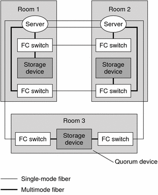
Figure 7–6 SPARC: Three-Room Campus Cluster (Sun StorEdge A5x00 as Quorum Device)
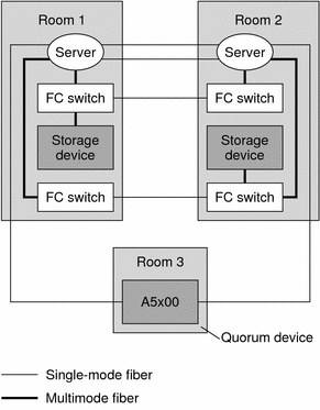
In Figure 7–6, note the absence of FC switches in Room 3. The storage array connection is made through a Sun StorEdge Dual FC Network Adapter and long-wave GBICs.
SPARC: Two-Room Examples
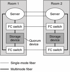
Figure 7–7 shows a two-room campus cluster that uses partner pairs of storage devices and four FC switches, with a multipathing solution implemented. The four switches are added to the cluster for greater redundancy and potentially better I/O throughput. This configuration could be implemented by using Sun StorEdge T3 partner groups or Sun StorEdge 9910/9960 arrays with Sun StorEdge Traffic Manager software installed.
For information about Traffic Manager software, see the Sun StorEdge Traffic Manager Installation and Configuration Guide at http://www.sun.com/products-n-solutions/hardware/docs/.
Figure 7–7 SPARC: Two-Room Campus Cluster With a Multipathing Solution Implemented
The configuration in Figure 7–8 could be implemented by using Sun StorEdge T3 or T3+ arrays in single-controller configurations, rather than partner groups.
Figure 7–8 SPARC: Two-Room Campus Cluster Without a Multipathing Solution Implemented
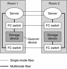
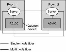
Figure 7–9 depicts a two-room campus cluster that uses Sun StorEdge A5x00s. Note the absence of switches.
Figure 7–9 SPARC: Two-Room Configuration (Sun StorEdge A5x00s)
- © 2010, Oracle Corporation and/or its affiliates
