| C H A P T E R 3 |
|
Installing the Sun StorEdge S1 Array |
This chapter provides instructions on preparing the area, connecting the cables, and powering on the array.
This chapter is organized as follows:
The Sun StorEdge S1 array can be mounted in a two-post rack using the brackets supplied in the ship kit, or in a four-post rack or cabinet using separately-ordered brackets described in Optional Rackmounting Kit for Four-Post Racks.
This section covers the following topics:
Follow these precautions to avoid injury to yourself and damage to your equipment:

|
Caution - Make sure that each system is grounded to the rack, and that each rack is connected to ground in the building. |
|
Note - See Optional Rackmounting Kit for Four-Post Racks for how to order the adjustable mounting brackets needed for a four-post rack or cabinet and for a list of components in the bracket's ship kit. |
This procedure can be used to install the Sun StorEdge S1 array into any of the four-post racks shown in TABLE 3-1. The table shows the number of arrays that fit into each type of rack or cabinet.
|
22 with cables that ship with the cabinet. If you order X option cables, part number X319YA, you can increase the number up to 32. |
|
1. Remove the parts from the accessory kit envelope.
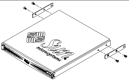
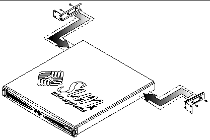
2. Use a Phillips screwdriver to attach the side mount brackets to the left and right sides of the array using the M4 x 8 flat head screws from the accessory kit.
As shown in the following figure, the open slot on one end of each bracket extends past the back of the array.
3. Align the two parts of each adjustable mounting bracket with the double-angled ear (A) in the correct position.
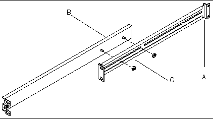
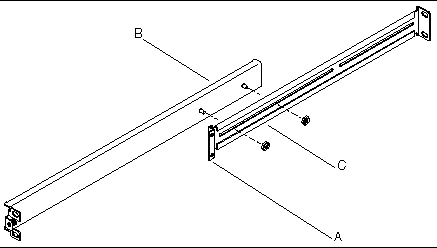
As shown in the following figures, one piece of the mounting bracket (B) is smooth except for two captive screws that extend from the same side as the mounting ear. The other piece of the mounting bracket (C) has two closed slots, and the end with the longest slot has a double-angled ear (A). Depending on which rack is being used, you position the double-angled end either towards the back or front of the array.
a. For a Sun StorEdge 72-inch expansion cabinet or a Sun Fire expansion cabinet, position the double-angled end (A) of the slotted piece (C) at the back, with the screws on the smooth piece (B) extending through the shorter slot of the slotted piece (FIGURE 3-2).
 [ D ]
[ D ]
b. For Sun Rack 900 and other industry standard 19" racks or cabinets, position the double-angled end (A) of the slotted piece (C) towards the front, with the screws on the smooth piece (B) extending through the longer slot of the slotted piece (FIGURE 3-3).
 [ D ]
[ D ]
4. Loosely secure the two parts of each bracket, tightening two of the M4 kep nuts supplied in the bracket's ship kit over the screws.
As shown in FIGURE 3-2 and FIGURE 3-3, the nuts are attached from the side of the bracket that faces the rack's posts (C).
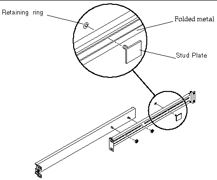
5. Insert the stud plate through the rightmost groove in the grooved bracket.
As shown in FIGURE 3-4, insert the stud plate from the same side of the bracket as the nuts were attached in the previous step.
|
Note - The bottom and top metal edges of the slotted piece of the bracket are folded. The bottom of the stud plate should lie flat between the two folds, and you should not be able to spin the plate. |
 [ D ]
[ D ]
6. Slide the retaining ring over the stud.
As shown in FIGURE 3-5, make sure the prongs on the retaining ring face away from the stud plate.
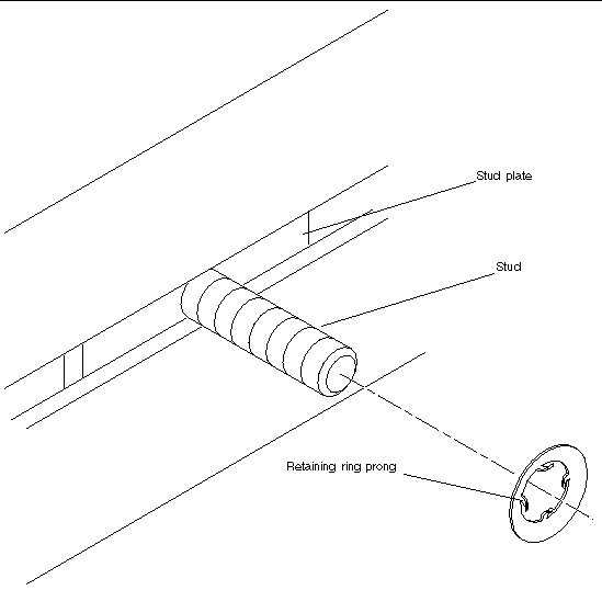
7. Press the retaining ring towards the bracket, using a 3/16 inch or equivalent nut driver.
Make sure the stud plate is firmly connected but that it is still able to slide along the bracket between the two folds.
8. Measure the distance between the front post and the post to which the back end of each bracket must be attached.
9. Adjust each bracket so that the distance between the front and the back mounting ears is approximately the same measurement as obtained in Step 8.
10. Align the holes in the bracket with the holes in the suitable posts and insert the appropriate screws, adjusting the depth of each bracket as required to fit.
a. Overlap the front ear of each bracket over the front edge of the front post.
b. Insert two screws into two holes in each bracket's front ear and through the front post, from front to back.
A third hole in the middle of the bracket's front ear is used later when securing the array.
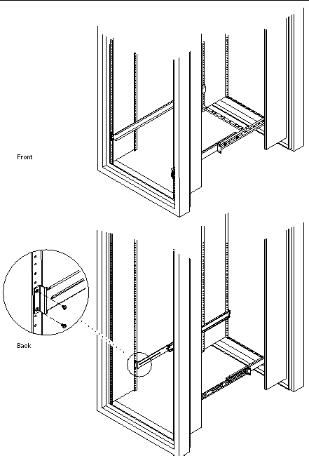
c. For a Sun StorEdge 72-inch expansion cabinet or Sun Fire expansion cabinet, perform the following steps to insert the back screws (FIGURE 3-6).
i. Align the screw holes at the back of each bracket over the holes in the third post from the front.
ii. Insert the back screws from the inside to the outside of the rack.
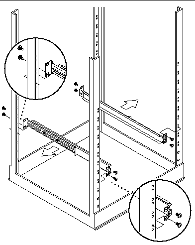
d. For a Sun Rack 900 or other industry-standard 19-inch rack, perform the following steps to insert the back screws (FIGURE 3-7).
i. Align the screw holes at the back of each bracket over the holes in the back post of the rack.
ii. Insert the back screws from the back towards the inside of the rack.
11. Tighten the M4 kep nuts that hold the two halves of the brackets together, using a 9/32 inch or equivalent nut driver.
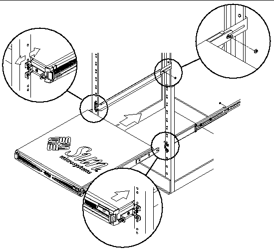
12. Slide the Sun StorEdge S1 array into the rack as far as it goes (FIGURE 3-8).
 [ D ]
[ D ]
13. Secure the captive screws on the front of the array into the front ear of each bracket on the front posts (FIGURE 3-9).
a. If necessary, readjust the bracket ears on the front post to align the system properly.
b. Insert the captive screws on the front edges of the array into the center hole on the front ear of each bracket, and tighten the thumbscrews finger-tight.
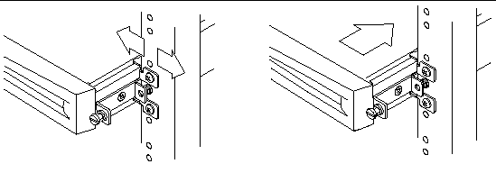
14. Slide the stud from the stud plate as far as it can go into the open slot on the side bracket that is attached to the back of the array (FIGURE 3-8).
15. Attach a kep nut from the accessory kit to each stud over its retaining ring, and tighten the kep nut with a 9/32 inch or equivalent nut driver.
16. Tighten the screws that hold the brackets in the rack if you have not fully secured them yet.
17. Use a straight-edge screwdriver to tighten the thumbscrews at the front to secure the array in the rack.
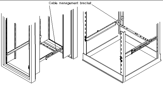
18. Hook the cable management bracket (FIGURE 3-10) over the mounting brackets behind the array.
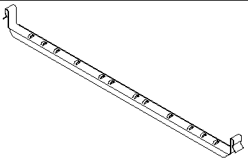
As shown in FIGURE 3-11, hook one end onto the left mounting bracket and hook one end onto the right mounting bracket so that the cable management bracket is parallel to the array's back.
19. Run cable ties through the holes in the cable management bracket.
20. After you attach the cables to the system, bundle them together and secure them with the cable ties.
For information on how to connect the cables see Connecting the SCSI Cables.
Use the following instructions to install the Sun StorEdge S1 array into a two-post rack, using the brackets and the Phillips head countersunk screws provided in the array's ship kit.
1. Use a Phillips screwdriver to attach the two brackets to the sides of the array.
a. For front-mounting, insert and tighten two screws through each bracket into the second and third tapped holes toward the front of the array (FIGURE 3-12).

b. For side-mounting, insert two screws through each bracket into the tapped holes towards the back of the array (FIGURE 3-13).
2. Position the array in the rack, insert, and tighten the screws.
a. For front mounting, overlap the holes on the front ear of each bracket over the corresponding holes on the fronts of the posts (FIGURE 3-14), and insert the screws.
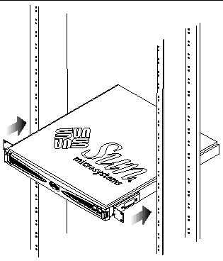 [ D ]
[ D ]
FIGURE 3-15 shows aligning the holes on the ears of each bracket with the corresponding two holes on the back of the posts.
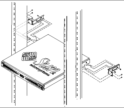 [ D ]
[ D ]Each of the array's three drive bays needs a SCSI ID assigned, whether or not a disk drive occupies the bay. The three SCSI IDs must be sequential numbers. All SCSI IDs in the series must not be assigned to another peripheral or SCSI controller. So, for example, if you plan to assign SCSI IDs 2, 3, and 4, neither 2, 3, nor 4 can be assigned to any other device. See the following procedure:
This section provides example SCSI ID assignment for several configurations:
You set the SCSI IDs for the drives by setting only the base address, which is the first number in the sequence of SCSI IDs. For example, in the sequence of SCSI IDs 2, 3, and 4, the base SCSI ID address is 2 (FIGURE 3-16).

See this procedure for how to set the base address:
FIGURE 3-17 and TABLE 3-2 show an example with two Sun StorEdge S1 arrays connected to a Netra T1 Model 100 or Netra T1 105 server's on-board SCSI port. Limitations of this configuration include:
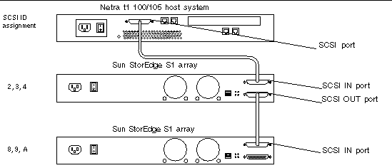 [ D ]
[ D ]
FIGURE 3-18 and TABLE 3-3 show an example of a host system with four Sun StorEdge S1 arrays connected to its on-board LVD SCSI port. This configuration has fewer limitations than the single-ended configuration in Example: Single-Ended SCSI Configuration:
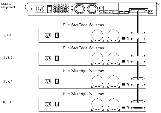 [ D ]
[ D ]
FIGURE 3-19 and TABLE 3-4 show an example of a host system with one single-ended Netra st D130 storage array and one Sun StorEdge S1 array connected to its LVD SCSI PCI adapter. This configuration has many limitations:
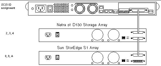 [ D ]
[ D ]
1. Determine which SCSI IDs are available.
a. Exclude the default SCSI controller ID number 7, unless the controller ID has been modified from the default.
b. Exclude any other SCSI IDs that may already be assigned by the host system.
c. Exclude the SCSI ID of any external SCSI device that is already connected to the SCSI bus.
Refer to the Solaris Handbook for Sun Peripherals for more details about how to determine which SCSI target IDs are available for your system.
2. Pick a base address for the SCSI ID sequence that you plan to assign to the drives.
|
Note - Make sure that you do not assign any previously-assigned SCSI IDs from Step 1. |
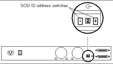
1. At the back of the array, locate the SCSI ID switch (FIGURE 3-20).
 [ D ]
[ D ]
Pressing the right switch with a pointed object increments the address. Pressing the left switch decrements the address.
2. Set the SCSI ID to the number of the base address (first address in the drive series).
For example, to use SCSI ID addresses 2, 3, and 4 for the first Sun StorEdge S1 array, set the SCSI toggle switch to 2.
3. If the power is On, cycle it Off then On again.
This step is essential to transfer the updated data to the drives.
4. Repeat Steps 2 and 3 for any additional Sun StorEdge S1 arrays that you may be installing.
|
Note - To get the correct SCSI data, the host server must be powered on after any attached SCSI devices, such as the Sun StorEdge S1 array. |
This section contains instructions for connecting SCSI cables and power cables to the Sun StorEdge S1 array. The following restrictions apply:
Include the internal SCSI bus length for the array, which is 0.2 meter, when calculating the total SCSI bus length. If you are connecting another type of peripheral in a daisy chain, refer to the documentation that you received with that peripheral for its internal SCSI bus length. For an example procedure for LVD SCSI, see To Cable Four Arrays in a Daisy Chain.
Before connecting the SCSI cables from the host system to the Sun StorEdge S1 array, you must prepare the host system.
|
Note - If the host system supports hot-swap attaching and detaching of external SCSI devices, do not power off the system. For example, Netra ct 400 and Netra ct 800 servers support hot-swapping of external SCSI devices, so you would not power off these system before starting. Start the host system preparation at Step 2. |
1. Halt operations and power off the host system.
Refer to the host system documentation for instructions on powering off the system.
2. Install a host bus adapter into the host system, if necessary.
Refer to the documentation that shipped with the host bus adapter for installation instructions.
3. Ensure that software documents (on the system CD) are available during the installation.
1. Verify that the host system has been powered off (if needed).
Refer to To Prepare the Host System.
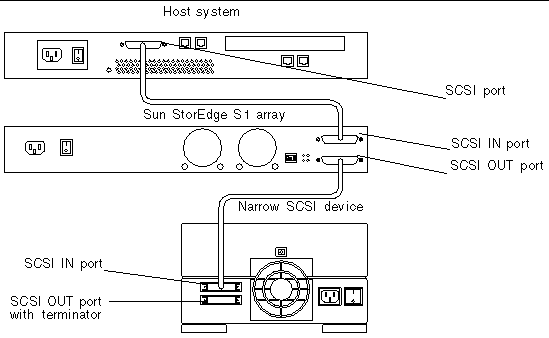
2. Connect the SCSI cable to the host system.
You can connect a cable to a host bus adapter or an on-board connector.
3. Connect the other end of the SCSI cable to the SCSI IN port at the back of the array.

4. Determine if this array is at the beginning or the end of the SCSI chain.
5. Connect one end of the SCSI cable to the SCSI OUT port of the first array.
6. Connect the other end of the SCSI cable to the SCSI IN port on the second array array or peripheral.
7. Repeat Step 5 and Step 6 until all arrays are attached to the daisy chain.
8. Determine if you need to install an external terminator at the end of the daisy chain.
Refer to the documentation that came with the wide SCSI device to determine if the device needs an external terminator.
|
Note - Wide SCSI Devices use a 16- or 32-bit bus and transmit twice as much data as a narrow SCSI device. |
 [ D ]
[ D ]The following example shows which cables you would use to cable four arrays in a daisy chain without exceeding the 12 meter limit for LVD SCSI. See FIGURE 3-17 through FIGURE 3-19 starting on "Invalid Cross-Reference Format" for some more examples of cabling configurations.
1. Connect the array to the host bus adapter using one 0.2 meter SCSI-3 to VHDCI cable.
2. Connect the four arrays using three 0.8 meter SCSI-3 to SCSI-3s cables.
TABLE 3-2 shows the part numbers for these cables.
The procedures for connecting and disconnecting the power cable(s) vary depending on whether you have the AC or the DC version of the Sun StorEdge S1 array:
|
Note - See Electrical Site Requirements for information on electrical site requirements. |
Disconnecting the AC power cable is a simple matter of removing the cable from the power source and from the array.
See this procedure for how to disconnect the DC power cable:
1. Connect the AC power cable to the AC power connector on the Sun StorEdge S1 array.

2. Connect the AC power cable to an AC power source.
|
Note - As soon as the array is connected to a power source, it goes into Standby mode. The amber System Summary Fault LED comes on to reflect this; it does not indicate a fault. |
1. Get a DC grounding cable and two star washers.
2. Position and align the DC grounding cable against the two DC grounding lug nuts at the back of the array.

3. Place the star washers between the DC grounding cable and the two bolts to be used to secure one end of the grounding cable to the two lug nuts.
4. Tighten the two bolts to secure the grounding cable to the two lug nuts.
5. Secure the other end of the grounding cable to the earth ground in the building.
If you are installing the array in a rack, you can secure the grounding cable to a proper grounding point on the rack, as long as the rack is properly grounded to the earth ground in the building.
6. Verify that the circuit breakers are Off on the circuits that supply power to the DC power source.

|
Caution - Make sure the circuit breakers are Off before proceeding with the next step. |
7. Assemble the DC input power cables, if necessary, connecting them to two different power sources through the circuit breakers.
Refer to Assembling the DC Input Power Cable (for DC Power Supplies) if you have not already assembled the DC input cables.
8. Connect one DC input power cable to a DC connector at the back of the array.
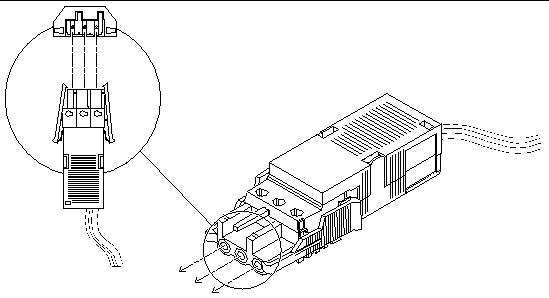 [ D ]
[ D ]
See FIGURE 3-26 for the locations of the DC connectors on the DC power supplies at the back of the array.

9. Repeat Step 8, connecting the second DC input power cable to the second DC connector at the back of the array.
10. Turn on the circuit breakers to provide power to the array.
|
Note - As soon as the system is connected to a power source, it goes into Standby mode. The amber System Summary Fault LED comes on to reflect this; it does not indicate a fault. |
 Squeeze the two tabs on the sides of the DC input power cable and gently disconnect the DC input power cable from the DC power supply (FIGURE 3-27).

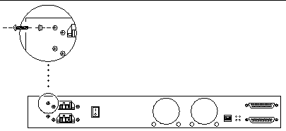
Every array is shipped from the factory with the chassis ground connected to the common output return through two screws on the power supply at the back of the array.
1. Go to the back of the array and locate the two screws used to isolate the chassis ground connection.

2. Unscrew the two chassis ground connection screws.
|
Note - Do not remove the two screws that hold the left side of the DC connectors in place. Remove the two screws further to the left of the DC connectors, which are raised slightly from the chassis. |
3. Locate the two chassis ground isolation bushings in the ship kit.
4. Insert the two bushings and screws into the screw holes and tighten the screws.
After all of the SCSI cables and power cables are attached to the Sun StorEdge S1 array, power on the array as described in the following procedure.
1. Before turning the array's power on, check the binary SCSI LED display with the power in standby mode.
See To Check the Binary SCSI ID LED Display for information on reading the binary LED display.
2. Press the power switch at the back of the array to the On (|) position.
See FIGURE 3-21 for the location of the power switch. Note that when you release the power switch, it settles into the center (neutral) position, the power remains on, and the system summary fault LED on the front and back panels turns from amber to green.
3. Check the LEDs to verify that the array is running properly.
See Checking Front Panel LEDs and Checking Back Panel LEDs for descriptions of the LED operations.
1. Make sure that the Sun StorEdge S1 array and all other peripheral devices connected to the host system are powered on.
2. If you have powered off the host system, power on the host system.
Refer to the host system documentation for the correct instructions.
3. Determine if the host system supports the hot-swap attachment of external SCSI devices.
For example, the Netra ct 400 and 800 servers support attaching SCSI devices in a hot-swap mode. Refer to your system documentation to see if your system supports hot swap.
a. As superuser, use the shutdown command to halt the host system.
# shutdown -y -i0 -g0 |
b. At the ok prompt, use the boot -r command to perform a reconfiguration boot on the system.
If you do not use the -r argument, the system does not see the new device.
ok boot -r |
4. Verify that the Sun StorEdge S1 array has successfully connected to the host system.
Refer to the host system documentation for specific instructions.
The following procedure uses example of hot-swapping a disk attached to controller 7.
1. Enter the cfgadm(1M) command with the -al option to list all the SCSI devices on the controller.
The screen example shows the results of listing controller c7.
2. Enter the cfgadm(1M) command with the -x remove_device option to remove the disk.
The screen example shows the removal of disk c7::dsk/c7t13d0.
3. Enter the cfgadm(1M) command with the -al option again to show that the disk has been removed.
The screen example shows that c7::dsk/c7t13d0 has been removed.
4. Enter the cfgadm command with the -x insert_device option to prepare to insert a new disk into the slot.
After entering the command, enter y when prompted to Continue (yes/no)?, as shown in the following screen example.
5. If replacing a disk, insert the replacement disk.
Enter y when prompted as shown in the following screen example.
Enter y if operation is complete or n to abort (yes/no)? y <sio@qame2-b>: |
7. Enter the cfgadm(1M) command with the -al option again to show that the disk has been added.
Copyright © 2003, Sun Microsystems, Inc. All rights reserved.