| C H A P T E R 2 |
 Preparing to Service the System
 |
This chapter describes how to prepare the Sun Blade X6275 server module for servicing. This includes preparatory service procedures, a list of required tools and supplies, and information about obtaining up-to-date supported components and part numbers.
The following basic procedures describe how to prepare the server module for service. The procedures describe how to safely remove the server module from the chassis and how to remove the server module’s top cover. These procedures are referenced throughout this manual.
The following topics are covered:
This section describes important safety information that you need to know prior to removing or installing parts in the Sun Blade X6275 server module.

|
Caution - Never attempt to run the server module with the cover removed. Hazardous voltage present. |

|
Caution - Equipment damage possible. The server module cover must be in place for proper air flow. |
For your protection, observe the following safety precautions when setting up your equipment:
The Sun Blade X6275 server module can be serviced with the following tools:
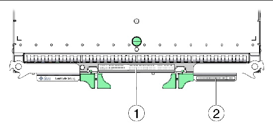
To obtain support for your server module, you need your serial number. The serial number is located on a label on the front ejector of the server module. Another label, which requires server module removal, is on the top of the server module as shown in FIGURE 2-1.
FIGURE 2-1 Serial Number Labels
To remove main power from the server module, choose one of the methods described in the following table.
|
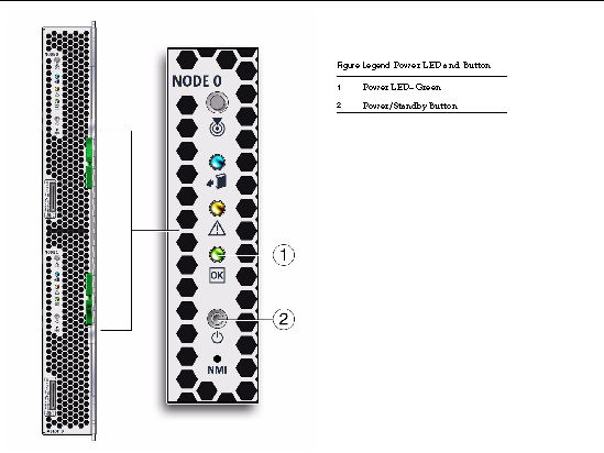
Use a pen, or other non-conducting pointed object, to press and release the Power/Standby Button on the front panel. When the main power is off, the OK LED on the front panel blinks, indicating that the server module is in standby power mode.
Pressing the Power/Standby Button causes Advanced Configuration and Power Interface (ACPI)-enabled operating systems to perform an orderly shutdown of the operating system. Server modules not running ACPI-enabled operating systems might ignore this event and the host will not shut down. |
|
|
Press and hold the Power/Standby Button for at least four seconds until the main power is off and the server module enters standby power mode. See FIGURE 2-2. When the main power is off, the OK LED on the front panel flashes, indicating that the server module is in standby power mode. |
|
|
|
|
|
To completely power off the server module, you must disengage the server module from the midplane connector inside the chassis. To completely remove power from a server module, do the following: |

|
Caution - Do not reinsert a server module until at least 20 seconds has elapsed since the server module was disengaged from the midplane connector. |
FIGURE 2-2 Front Panel OK LED and Power/Standby Button
You can use the service processor Command-Line Interface (CLI) to perform a graceful shutdown of the server module and ensure that all of the data is saved and the server module is ready for restart.
Refer to the ILOM and operating system documentation for additional information.
1. Log in as a superuser or equivalent.
Depending on the type of problem, you might want to view server module status or log files, or run diagnostics before you shut down the server module.
3. Save any open files and quit all running programs.
Refer to your application documentation for specific information.
4. Open an SSH session to the SP.
5. Log into the Service Processor.
The default user name is root and the password is changeme.
7. Repeat this procedure for the second compute node.
You can use the service processor web interface to perform a graceful shutdown of the server module and ensure that all of your data is saved and the server module is ready for restart.
Refer to the ILOM and operating system documentation for additional information.
1. Log in as a superuser or equivalent.
Depending on the type of problem, you might want to view server module status or log files, or run diagnostics before you shut down the server module.
3. Save any open files and quit all running programs.
Refer to your application documentation for specific information.
4. Open a web browser and enter the SP IP address in the location bar.
5. Log in to the Service Processor Web Interface.
The default user name is root and the password is changeme.
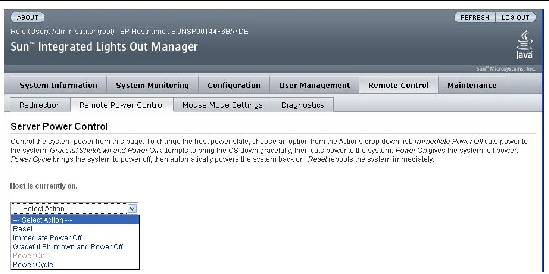
6. Click the Remote Control tab, the Remote Power Control tab and then select Graceful Shutdown and Power Off from the drop-down list. See FIGURE 2-3.
8. Repeat this procedure for the second compute node.
FIGURE 2-3 Web Interface Power Off
The server module must be removed from the Sun Blade 6048 or Sun Blade 6000 chassis to:

|
Caution - Do not reinsert a server module until at least 20 seconds has elapsed since the server module was disengaged from the midplane connector. |
To remove the server module from the Sun Blade 6048 or Sun Blade 6000 chassis.
1. Power off both server module compute nodes or place them in standby power mode.
See Powering Off the Server Module for more information.
When the server module compute nodes are in standby power mode, the OK LEDs blink (0.1 second on, 2.9 seconds off) on the front panel.
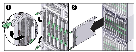
2. Squeeze and hold green ejector buttons. See FIGURE 2-4.
3. Open the ejector levers by rotating both ejector arms away from the server module at the same time, to unseat the server module from the Sun Blade chassis connector.
4. Pull the server module out of the Sun Blade chassis by the ejector levers until you are able to grasp the server module with both hands to pull it out of the Sun Blade chassis.
5. Insert a server module filler panel into the empty slot, if the Sun Blade chassis is powered on.

|
Caution - Do not operate the system with empty slots. Always insert a server module filler panel into an empty slot within 60 seconds to reduce the possibility of server module shutdown. |
6. Set the server module on an antistatic surface. See the next section.
FIGURE 2-4 Removing a Server Module (Sun Blade 6048 Chassis Shown)
Electrostatic discharge (ESD) sensitive devices, such as the motherboards, drives, and memory DIMMs, require special handling.
Wear an antistatic wrist strap and use an antistatic mat when handling components such as hard drive assemblies, circuit boards, or PCI cards. When servicing or removing server components, attach an antistatic strap to your wrist and then to a metal area on the chassis. Following this practice equalizes the electrical potentials between you and the server.
| Note - An antistatic wrist strap is not included in the accessory kit for the Sun Blade X6275 server module. However, antistatic wrist straps are included with options. |
Place ESD-sensitive components such as motherboards, memory, and other PCBs on an antistatic mat.
1. Prepare an antistatic surface to set parts on during the removal, installation, or replacement process.
Place ESD-sensitive components such as the printed circuit boards on an antistatic mat. The following items can be used as an antistatic mat:
2. Attach an antistatic wrist strap.
When servicing or removing server module components, attach an antistatic strap to your wrist and then to a metal area on the chassis.
1. Power down both server module compute nodes.
See Powering Off the Server Module.
2. Remove the server module from the chassis. Place it on a flat surface.
See Removing the Server Module From the Sun Blade Chassis.
3. Attach an antistatic wrist strap.
See Performing Electrostatic Discharge and Antistatic Prevention Measures.
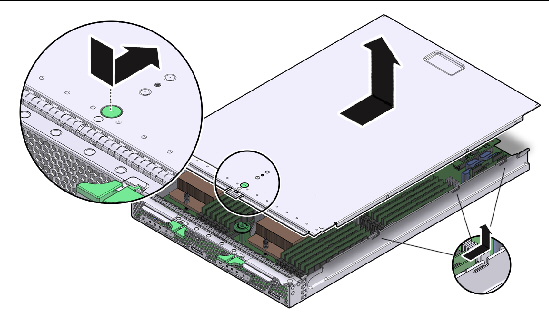
4. Press down on the server module cover release button and, using the indent for leverage, slide the main cover toward the rear of the server module chassis approximately 0.5 inch (12 mm). See FIGURE 2-5.
5. Grasp the server module cover by its rear edge and lift it straight up from the server module chassis.
FIGURE 2-5 Removing the Server Module Top Cover
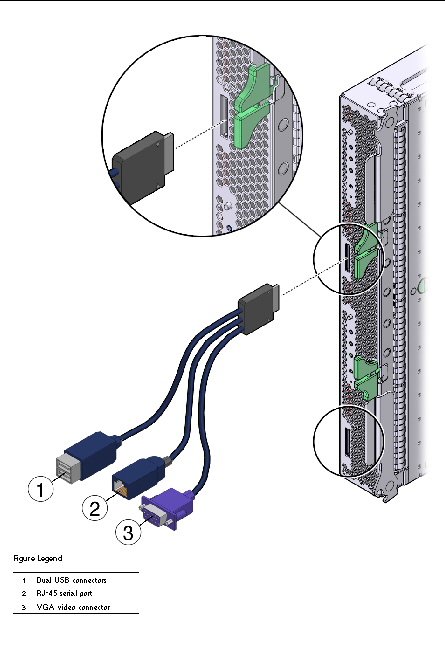
Your chassis might ship with a multi-port dongle cable and a DB9 to RJ-45 serial adapter cable. You can use the multi-port cable to plug devices directly into the front of the server module for service, maintenance, and OS installation.
The multi-port cable provides connections for a VGA monitor, two USB devices, and a serial device.
The DB9 to RJ-45 serial adapter cable provides DB9 serial access to the server module through an RJ-45 connection.
Your multi-port dongle cable might have three cables or four cables. If your multi-port cable has three cables, connect to the serial port using the RJ-45 connector.
If your multi-port cable has four cables, connect to the serial port using the DB9 connector, and do not use the RJ-45 connector. Use the DB9 to RJ-45 adapter cable, if necessary.
1. Insert the multi-port dongle cable into the universal connector port (UCP) on the server module front panel. See FIGURE 2-6.
2. Connect the multi-port dongle cable connections as appropriate.
Use the locate button and locate LED to identify a server module within a fully populated chassis.
|
1. Access the ILOM Web Interface.
2. On the Web Interface, navigate to System Monitoring - Indicators.
3. Select the radio button next to /SYS/LOCATE.
4. Select: Turn LED On, or Set LED to Fast Blink, from the drop-down menu.
|
 Type: set /SYS/LOCATE value=Fast_Blink
|
 Type: set /SYS/LOCATE value=Off

Copyright © 2012, Oracle and/or its affiliates. All rights reserved.