| C H A P T E R 4 |
 Returning the Server Module to Operation
 |
This chapter describes how to return the Sun Blade X6275 server module to operation after you have performed service procedures.
The following topics are covered in this chapter:

|
Caution - Never attempt to run the server module with the cover removed. Hazardous voltage present. |

|
Caution - Equipment damage possible. The server module cover must be in place for proper air flow. |
If you removed the server module top cover, perform the following steps to replace it:
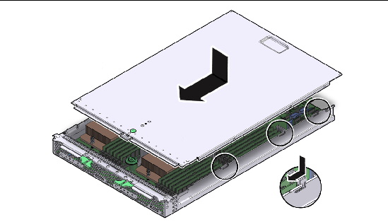
1. Grasp the server module cover by its rear edge and place it down on the server module chassis. See FIGURE 4-1.
2. Slide the main cover toward the front of the server module chassis approximately 0.5 inch (12 mm). Slide the cover under the tabs at the front of the server module.
3. Gently press down on the server module cover to engage it with the server module chassis.
4. When applicable, install the server module in the Sun Blade chassis and power on the server module.
FIGURE 4-1 Installing the Server Module Top Cover

If you removed the server module from the chassis, perform these steps to replace it:
1. Locate the desired slot in the Sun Blade chassis.
2. Remove the server module filler panel.
Pull the lever out and eject the server module filler panel.
Do not discard the server module filler panel.
3. Position the server module vertically so that the ejectors are on the right.
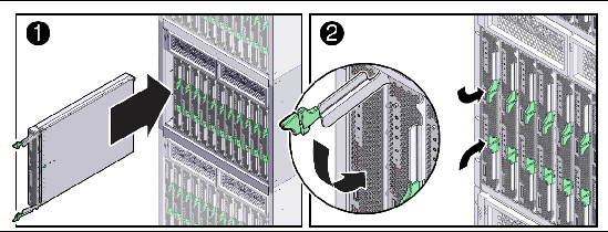
FIGURE 4-2 [1] shows the server module being inserted into the Sun Blade 6048 chassis. Your chassis might differ.
4. Push the server module into the slot until the server module stops. [2]
5. Rotate the ejectors down until they snap into place.
The server module is now flush with the chassis, and the ejectors are locked.
If the chassis is powered on, the server module comes up to standby power. The green OK LED on the front panel blinks (0.1 seconds on, 2.9 seconds off).
FIGURE 4-2 Inserting the Server Module.

Before powering on your server module for the first time, follow the installation and cabling instructions provided in the Sun Blade X6275 Server Module Installation Guide, which is shipped with the server module and is also available online at http://docs.sun.com.
When the server module is inserted in to the chassis, the server module automatically powers on.
To apply power to the server module, choose a method described in TABLE 4-1.
|
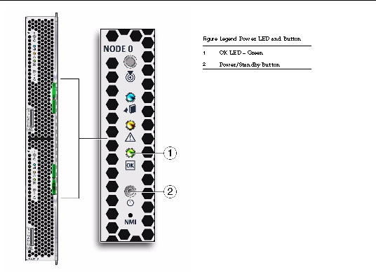
Place the server module into the chassis. See Reinstalling the Server Module in the Sun Blade Chassis. When the main power is off, the server module green OK LED on the front panel blinks once every three seconds, indicating that the server module is in standby power mode. See FIGURE 4-3. |
|
|
To apply main power to the server module: In standby power mode, the green OK LED on the front panel blinks.
When the main power is applied to the server module, the green OK LED next to the Power/Standby Button lights and remains lit. See FIGURE 4-3. |
FIGURE 4-3 Front Panel OK LED and Power/Standby Button


Copyright © 2012, Oracle and/or its affiliates. All rights reserved.