| Sun Blade X6275 Server Module Installation Guide |
| C H A P T E R 1 |
|
Preparing to Install the Sun Blade X6275 Server Module |
This chapter contains the following topics:
TABLE 1-1 summarizes how to install a Sun Blade X6275 server module into a Sun Blade 6048 or Sun Blade 6000 modular system chassis.
|
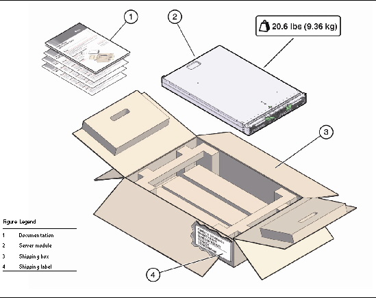
Unpack the server module and any optional components ordered for the server from the shipping containers. |
|
|
|
Register the server module. Locate the serial number on the label on top of the server module. |
Go to this web site:
|
|
|
If applicable, install the optional server module components before you install the server module into the chassis. |
||
|
Ensure that the following tasks are complete before you install the Sun Blade X6275 server module into the Sun Blade modular system.
1. Review the required installation tasks for properly installing and setting up the Sun Blade X6275 server module in a Sun Blade 6048 or Sun Blade 6000 modular system. See TABLE 1-1 Installation Task Summary.
2. Review the safety documents:
3. Ensure that the following chassis components have been installed and powered on in a Sun Blade 6048 or Sun Blade 6000 modular system.
For information about installing chassis components, attaching cables, and powering on the chassis, refer to the Sun Blade 6048 or Sun Blade 6000 modular system chassis documentation at: http://docs.sun.com/app/docs/prod/blade.srvr#hic
For information about Q-NEMs on the chassis, go to http://docs.sun.com/app/docs/prod/blade.6048mod~blade6048#hic
4. Assemble all tools and equipment needed.
To install the system, you must have the following tools:
Electrostatic discharge (ESD) mat and antistatic grounding strap
(required if you install optional components)
In addition, you must provide a system console device, such as one of the following:
5. See Opening the Box.
1. Carefully open the shipping box.
2. Unpack all server components from the packing carton. See FIGURE 1-1 and FIGURE 1-2.
FIGURE 1-1 Shipping Box Contents (Multiple Blades)

FIGURE 1-2 Shipping Box Contents (Single Blade)
3. If applicable, install optional server module components prior to installing the server module into the system chassis. Example: DIMMs, FMods, USB flash disks.
For optional components available for the Sun Blade X6275 server module, see Additional Options and Replaceable Components. Also see About Your Server Module Shipment. Refer to the Sun Blade X6275 Server Module Service Manual for installation procedures of optional components.
4. Register the server module.
Locate the serial number on the label on top of the server module. To register, go to this web site: http://www.sun.com/service/warranty/index.xml#reg
5. Proceed to Installing and Powering On the Sun Blade X6275 Server Module.
Configurations for the Sun Blade X6275 server module are assembled at the factory and shipped ready for installation in a Sun Blade modular system.
Optional server module components that you purchase independent of the standard configuration are shipped separately and, in most cases, should be installed before you install the server module into the chassis. For optional components available for the Sun Blade X6275 server module, see Additional Options and Replaceable Components.
If you ordered any options that are field replaceable units (FRUs) or Customer Replaceable Units (CRUs), refer to the Sun Blade X6275 Service Label on the top cover or the Sun Blade X6275 Server Module Service Manual for installation instructions.
If you ordered any options that are not factory-installed, refer to the documentation provided with the option for installation instructions.
On a Sun Blade 6048 Modular System, the Sun Blade X6275 Service Card (with a center tab) is located in a slot on the front right side of the system chassis rack, along with the Sun Blade 6048 Modular System Chassis Service Card. A service label on the blade cover will replace the Service Card.
| Note - These servers are fully compliant with the Reduction of Hazardous Substances (RoHS) Directive. |
Optional components are shipped separately for customer installation.
Supported components and their part numbers are subject to change over time and without notice. For the most up-to-date list, go to:
http://sunsolve.sun.com/handbook_pub/Systems/
Click the name and model of your server. On the product page that opens for the server, click on Full Components List for a list of components.
The following optional server module components may be ordered and purchased separately:
The following table identifies some terms commonly used in this guide to describe the installation of a Sun Blade X6275 server module into a Sun Blade modular system chassis.
|
Sun Blade X6275 server module hardware. The X6275 Blade Server Module, which is the physical blade that plugs into a Sun modular system chassis. The Sun Blade X6275 server module contains two independent nodes. |
|
|
Either of the two independent x64 computers resident on the server blade. |
|
|
Sun Blade 6048 modular system or Sun Blade 6000 modular system hardware.
For additional information about the Sun Blade 6000 modular system, go to http://docs.sun.com/app/docs/coll/blade6000. |
|
|
Integrated Lights Out Manager (ILOM) is the embedded management software that runs on the server module SP and CMM SP that enables you to manage your system. For additional information about ILOM, refer to the Integrated Lights Out Manager documentation. |
|
|
Embedded service processor (SP) on the server module and Chassis Monitoring Module (CMM). The SP is a “baseboard management controller” (BMC). Each of the two servers on the server blade has its own dedicated SP. |
|
|
Chassis Monitoring Module. A baseboard management controller (BMC) for the entire Sun modular system chassis. |
|
| Sun Blade X6275 Server Module Installation Guide | 820-6977-11 |
Copyright © 2009 Sun Microsystems, Inc. All rights reserved.