Preparing to Install the Sun Fire X4170, X4270, and X4275 Servers
|
This chapter describes the Sun Fire X4170, X4270, and X4275 Servers hardware and the information you need to know before you begin to install the servers into a rack. It includes the following topics:
Tools and Equipment Needed
To install the system, you need the following tools:
- No. 2 Phillips screwdriver
- ESD mat and grounding strap
- Pencil, stylus, or other pointed device, for pushing front panel buttons
You also need a system console device, such as one of the following:
- Sun workstation
- ASCII terminal
- Terminal server
- Patch panel connected to a terminal server
Server Installation Task Checklist
TABLE 1-1 summarizes an ordered list of tasks that you must perform to properly install the server.
TABLE 1-1 Installation Task Checklist
|
Step
|
Task Description
|
For Instructions, See:
|
|
1
|
Unpack the server and any optional components ordered for the server from the shipping containers
|
|
|
2
|
If applicable, install the optional server module components prior to installing the server module into the chassis
|
|
|
3
|
Install the server into a rack
|
|
|
4
|
Connect cables to the server, configure the ILOM service processor, and apply main power to the server
|
|
|
5
|
If ordered, configure the factory-installed Solaris or OpenSolaris Operating System image shipped on one of the storage drives
|
|
|
If applicable, install one of the following operating systems:
- Red Hat Enterprise Linux
- SUSE Linux Enterprise Server 10
- Solaris 10 Operating System
- OpenSolaris Operating System
- VMware
|
- Sun Fire X4170, X4270, and X4275 Servers Linux, VMware, Solaris, and OpenSolaris Operating Systems Installation Guide (820-5828)
|
- Microsoft Windows Server 2003 or 2008 Operating System
|
- Sun Fire X4170, X4270, and X4275 Servers Windows Operating System Installation Guide (820-5829)
|
Opening the Box
Carefully open the shipping box.
Unpacking
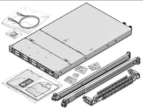
Unpack all server components from the packing cartons. FIGURE 1-1 shows the packing contents:
FIGURE 1-1 Unpacking the Box

Package Contents Inventory
The following items should be packaged with the Sun Fire X4170, X4270, and X4275 Servers:
- Sun Fire X4170, X4270, or X4275 Server
- Power cord, packaged separately with country kit
- (Optional) Sun Fire X4170, X4270, and X4275 Server Documentation and Media Kit, including the following:
- Sun Fire X4170, X4270, and X4275 Servers Installation Guide (this document)
- License and safety documentation
- Tools & Drivers DVD (includes drivers and additional software), Sun Installation Assistant (SIA) CD/DVD, and SunVTS CD/DVD
- (Optional) Rackmount kit containing rack rails and installation instructions
Options
Power cables are packaged separately from the other items.
Standard server components are installed at the factory. However, ordered options such as additional memory or PCI Express cards are shipped separately. If possible, install optional components before installing the server in a rack. For instructions for installing server options, see Installing Server Options.
ESD Precautions
Electronic equipment is susceptible to damage by static electricity. Use a grounded antistatic wriststrap, footstrap, or equivalent safety equipment to prevent electrostatic discharge (ESD) when you install or service the server.

|
Caution - To protect electronic components from electrostatic discharge, which can permanently disable the system or require repair by Sun service technicians, place components on an antistatic surface, such as an antistatic discharge mat, an antistatic bag, or a disposable antistatic mat. Wear an antistatic grounding strap connected to a metal surface on the chassis when you work on system components.
|
Server Description
This section shows the front and back of the Sun Fire X4170, X4270, and X4275 Servers.
Front Panel Features
FIGURE 1-2 shows the Sun Fire X4170 Server front panel and describes its components.
FIGURE 1-2 Sun Fire X4170 Server Front Panel
 [ D ]
[ D ]
Figure Legend
|
1
|
Locator LED/Locator button: white
|
9
|
Hard disk drive 5 (optional)
|
|
2
|
Service Action Required LED: amber
|
10
|
Hard disk drive 4 (optional)
|
|
3
|
Power/OK LED: green
|
11
|
Hard disk drive 6 (optional)
|
|
4
|
Power button
|
12
|
Hard disk drive 7 (optional)
|
|
5
|
Hard disk drive 1 (optional)
|
13
|
DVD drive (optional)
|
|
6
|
Hard disk drive 0 (optional)
|
14
|
USB 2.0 connector (2)
|
|
7
|
Hard disk drive 3 (optional)
|
15
|
USB 2.0 connector (3)
|
|
8
|
Hard disk drive 2 (optional)
|
16
|
Power Supply Service Action Required LED: amber
System Overtemperature LED: amber
Fan Module Service Action Required LED: amber
|
FIGURE 1-3 shows the Sun Fire X4270 front panel and describes its components.
FIGURE 1-3 Sun Fire X4270 Server Front Panel
 [ D ]
[ D ]
Figure Legend
|
1
|
Locator LED/Locator button: white
|
13
|
Hard disk drive 8 (optional)
|
|
2
|
Service Action Required LED: amber
|
14
|
Hard disk drive 9 (optional)
|
|
3
|
Power/OK LED: green
|
15
|
Hard disk drive 10 (optional)
|
|
4
|
Power button
|
16
|
Hard disk drive 11 (optional)
|
|
5
|
Hard disk drive 0 (optional)
|
17
|
Hard disk drive 12 (optional)
|
|
6
|
Hard disk drive 1 (optional)
|
18
|
Hard disk drive 13 (optional)
|
|
7
|
Hard disk drive 2 (optional)
|
19
|
Hard disk drive 14 (optional)
|
|
8
|
Hard disk drive 3 (optional)
|
20
|
Hard disk drive 15 (optional)
|
|
9
|
Hard disk drive 4 (optional)
|
21
|
DVD drive (optional)
|
|
10
|
Hard disk drive 5 (optional)
|
22
|
USB 2.0 connector (2)
|
|
11
|
Hard disk drive 6 (optional)
|
23
|
USB 2.0 connector (3)
|
|
12
|
Hard disk drive 7 (optional)
|
24
|
Power Supply Service Action Required LED: amber
System Overtemperature LED: amber
Fan Module Service Action Required LED: amber
|
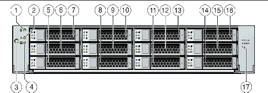
FIGURE 1-4 shows the Sun Fire X4275 Server front panel and describes its components.
FIGURE 1-4 Sun Fire X4275 Server Front Panel
 [ D ]
[ D ]
Figure Legend
|
1
|
Locator LED/Locator button: white
|
9
|
Hard disk drive 4 (optional)
|
|
2
|
Service Action Required LED: amber
|
10
|
Hard disk drive 5 (optional)
|
|
3
|
Power button
|
11
|
Hard disk drive 6 (optional)
|
|
4
|
Power/OK LED: green
|
12
|
Hard disk drive 7 (optional)
|
|
5
|
Hard disk drive 0 (optional)
|
13
|
Hard disk drive 8 (optional)
|
|
6
|
Hard disk drive 1 (optional)
|
14
|
Hard disk drive 9 (optional)
|
|
7
|
Hard disk drive 2 (optional)
|
15
|
Hard disk drive 10 (optional)
|
|
8
|
Hard disk drive 3 (optional)
|
16
|
Hard disk drive 11 (optional)
|
|
|
|
17
|
Fan Module Service Action Required LED: amber
Power Supply Service Action Required LED: amber
System Overtemperature LED: amber
|
Back Panel
FIGURE 1-5 shows the Sun Fire X4170 Server back panel and describes its components.
FIGURE 1-5 Sun Fire X4170 Server Back Panel
 [ D ]
[ D ]
Figure Legend
|
1
|
Power supply unit 0 connector
|
7
|
PCI Express Module slot (1)
|
|
2
|
Power supply unit 0 status indicator LEDs:
Power Supply OK: green
Power Supply Fail: amber
AC OK: green
|
8
|
PCI Express Module slot (2)
|
|
3
|
Power supply unit 1 connector
|
9
|
Serial management (SER MGT)/RJ-45 serial port
|
|
4
|
Power supply unit 1 status indicator LEDs:
Power Supply OK: green
Power Supply Fail: amber
AC OK: green
|
10
|
Service processor (SP) network management (NET MGT port)
|
|
5
|
System status LEDs:
Power: green
Attention: amber
Locate: white
|
11
|
Gigabit Ethernet ports NET 0, 1, 2, 3
|
|
6
|
PCI Express Module slot (0)
|
12
|
USB 2.0 ports (0, 1)
|
|
|
|
13
|
HD15 video connector (analog VGA)
|
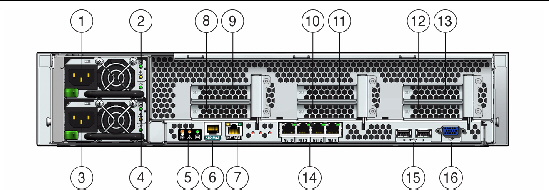
FIGURE 1-6 shows the Sun Fire X4270 and X4275 Servers back panels and describes their components.
FIGURE 1-6 Sun Fire X4270 and X4275 Servers Back Panel
 [ D ]
[ D ]
Figure Legend
|
1
|
Power supply unit 1 connector
|
9
|
PCI Express Module slot (3)
|
|
2
|
Power supply unit 1 status indicator LEDs:
Power Supply OK: green
Power Supply Fail: amber
AC OK: green
|
10
|
PCI Express Module slot (1)
|
|
3
|
Power supply unit 0 connector
|
11
|
PCI Express Module slot (4)
|
|
4
|
Power supply unit 0 status indicator LEDs:
Power Supply OK: green
Power Supply Fail: amber
AC OK: green
|
12
|
PCI Express Module slot (2)
|
|
5
|
System status LEDs:
Power: green
Attention: amber
Locate: white
|
13
|
PCI Express Module slot (5)
|
|
6
|
Serial management (SER MGT)/RJ-45 serial port
|
14
|
Gigabit Ethernet ports NET 0, 1, 2, 3
|
|
7
|
Service processor (SP) network management (NET MGT) port
|
15
|
USB 2.0 ports (0, 1)
|
|
8
|
PCI Express Module slot (0)
|
16
|
HD15 video connector (analog VGA)
|
Server Supported ComponentsSun Fire X4170 Server Supported Components and Capabilities

|
Caution - Configuration restriction:SATA disk drives are not supported on Sun Fire X4170 systems with CPUs that have a power consumption rating higher than 80 watts. Systems with 95-watt CPUs support SAS drives only.
|
The following table describes the components and capabilities of the Sun Fire X4170 Server.
TABLE 1-1 Sun Fire X4170 Server Com ponents
|
Component
|
X4170 Server
|
|
CPU
|
One or two quad-core processors with three integrated DDR3 memory controllers per processor. The following CPU sizes are supported:
- 2.26 GHz/80 Watts
- 2.40 GHz/60 Watts
- 2.53 GHz/80 Watts
- 2.93 GHz/95 Watts
|
|
Memory
|
Nine DIMMs per processor for a maximum of 18 DIMMs and a maximum of 144 GB of memory
|
|
Storage devices
|
- Up to six 2.5-inch SATA hard drive devices (HDDs) or four solid-state drives (SSDs)
- Up to eight 2.5-inch SAS/SATA HDDs or four SSDs with the optional Hardware RAID controller
- DVD-RW drive
- Compact Flash slot (internally accessible)
|
|
USB ports
|
Two front, two rear, and one internal
|
|
PCI Express 2.0 I/O slots
|
Three low-profile PCIe Gen2 slots (one x16, two x8) or three low-profile, 5.0 GT/s PCIe Gen2 slots (one x16, two x8)
|
|
PCI Express I/O cards
|
For a list of I/O cards that are customer-orderable options, go to the following web site and click on the options card link:
|
|
Ethernet ports
|
Four Gigabit Ethernet (GbE) ports on rear panel
Each Network Interface Card (NIC) supports I/O Acceleration Technology 3 (IOAT3)
|
|
Service processor
|
Uses the SP subsystem
Includes the Baseboard Management Controller (BMC), which supports the industry-standard IPMI feature set
Supports remote KVMS over IP
Includes serial port
Supports Ethernet access to SP through a dedicated 10/100BaseT management port and optionally through one of the host GbE ports (sideband management)
|
|
Power supplies
|
Up to two hot-pluggable power supplies
|
|
Cooling fans
|
Redundant hot-pluggable fans
|
|
Management software
|
Sun Integrated Lights Out Manager
|
Sun Fire X4270 and X4275 Servers Supported Components
The following table describes the components and capabilities of the Sun Fire X4270 and X4275 Servers.
TABLE 1-2 Sun Fire X4270 and X4275 Servers Com ponents and Capabilities
|
Component
|
X4270 and X4275 Servers
|
|
CPU
|
One or two quad-core processors with three integrated DDR3 memory controllers per processor. The following CPU sizes are supported:
- 2.26 GHz/80 Watts
- 2.40 GHz/60 Watts
- 2.53 GHz/80 Watts
- 2.93 GHz/95 Watts
|
|
Memory
|
Nine DDR3 DIMMs per processor for a maximum of 18 DDR3 DIMMs and a maximum of 144 GB of memory
|
|
Storage devices
|
Storage drives supported by the Sun Fire X4270 and X4275 Servers with the LSI 3081E SAS RAID controller (required):
- Up to sixteen 2.5-inch SAS/SATA HDDs (only supported on X4270 Server)
- Up to twelve 3.5-inch SAS/SATA HDDs (only supported on X4275 Server)
- DVD-RW drive (only supported on X4270 Server)
- CompactFlash slot (internally accessible)
Storage drives supported by the Sun Fire X4270 and X4275 Servers with Sun
StorageTek SAS RAID controller (required):
- Up to eight 2.5-inch SAS/SATA SDDs (only supported on X4270 Server)
- Up to sixteen 2.5-inch SAS/SATA HDDs (only supported on X4270 Server)
- Up to eight 3.5-inch SAS/SATA SSDs (only supported on X4275 Server)
- Up to twelve 3.5-inch SAS/SATA HDDs (only supported on X4275 Server)
- DVD-RW drive (only supported on X4270 Server)
- CompactFlash slot (internally accessible)
|
|
USB ports
|
X4270 Server: Two front, two rear, and one internal
X4275 Server: Two rear and one internal
|
|
PCI Express 2.0 I/O slots
|
Six x8 low-profile PCIe Gen2 slots or six low-profile PCIe Gen2 (5.0 GT/s) slots
|
|
PCI Express I/O cards
|
For a list of I/O cards that are customer-orderable options, go to the following web site and click on the options card link:
|
|
Ethernet ports
|
Four Gigabit Ethernet (GbE) ports on rear panel
Each Network Interface Card (NIC) supports I/O Acceleration Technology 3 (IOAT3)
|
|
Service processor
|
Uses the SP subsystem
Includes the Baseboard Management Controller (BMC), which supports the industry-standard IPMI feature set
Supports remote KVMS over IP
Includes a serial port
Supports Ethernet access to SP through a dedicated 10/100BaseT management port and optionally through one of the host GbE ports (sideband management)
|
|
Power supplies
|
Up to two hot-pluggable power supplies
|
|
Cooling fans
|
Redundant hot-pluggable fans
|
|
Management software
|
Supports Sun Integrated Lights Out Manager 2.0 and 3.0
|
Server SpecificationsPhysical Specifications
TABLE 1-3 lists the physical specifications of the Sun Fire X4170, X4270, and X4275 Servers.
TABLE 1-3 Servers Physical Specifications
|
Parameter
|
Sun Fire X4170 Server
|
Sun Fire X4270 Server
|
Sun Fire X4275 Server
|
|
Height
|
1.71 inches/43.43 mm
|
3.34 inches/84.84 mm
|
3.45 inches/87.6 mm
|
|
Width
|
16.75 inches/425.45 mm
|
16.75 inches/425.45 mm
|
17.2 inches/436.8 mm
|
|
Depth
|
28.0 inches/711.25 mm
|
28.0 inches/711.25 mm
|
30.13 inches/765.25 mm
|
|
Weight
|
36 lbs/16.36 kg
|
49 lbs/22.27 kg
|
65 lbs/29.54 kg
|
Electrical Specifications
TABLE 1-4 lists the electrical specifications for the Sun Fire X4170, X4270, and X4275 Servers.
| Note - The power dissipation numbers listed in the following table are the maximum rated power numbers for the power supply used in these servers. The numbers are not a rating of the actual power consumption of the system. For up to date information on the power consumption, see the power calculators for the Sun Fire X4170, X4270, and X4275 Servers on the web at: http://www.sun.com/powercalculators
|
TABLE 1-4 Servers Electrical Specifications
|
Parameter
|
Value
|
|
Sun Fire X4170 Server
|
|
|
Input
|
|
|
Nominal frequencies
|
50/60 Hz
|
|
Nominal voltage range
|
100-120/200-240 VAC
|
|
Maximum current AC RMS
|
8.8A @ 100 VAC
|
|
AC operating range
|
90-264 VAC
|
|
Output
|
|
|
3.3 VDC STBY
|
3.6A
|
|
+12 VDC
|
62.3 A
|
|
Power dissipation
|
|
|
Max power consumption
|
873 W
|
|
Max heat output
|
2977 BTU/hr
|
|
Volt-Ampere rating
|
891 VA @ 240 VAC, 0.98 P.F.
|
|
Sun Fire X4270 and X4275 Servers
|
|
|
Input
|
|
Nominal frequencies
|
50/60 Hz
|
|
Nominal voltage range
|
100-120/200-240 VAC
|
|
Maximum current AC RMS
|
13.8A @ 100 VAC
|
|
AC operating range
|
90-264 VAC
|
|
Output
|
|
|
3.3 VDC STBY
|
3.0 A
|
|
+12 VDC
|
86.7 A
|
|
Power dissipation
|
|
|
Max power consumption
|
1235.3 W
|
|
Max heat output
|
4212 BTU/hr
|
|
Volt-Ampere rating
|
1261 VA @ 240 VAC, 0.98 P.F.
|
Environmental Requirements
TABLE 1-5 lists the environmental requirements for the Sun Fire X4170, X4270, and X4275 Servers.
TABLE 1-5 Servers Environmental Requirements
|
Parameter
|
Value
|
|
Operating temperature (single, non-rack system)
|
5o C to 35o C (41o F to 95o F)
|
|
Nonoperating temperature (single, non-rack system)
|
-40o C to 70o C (-40o F to 158o F)
|
|
Operating humidity (single, non-rack system)
|
10% to 90% relative humidity, non-condensing
|
|
Nonoperating humidity (single, non-rack system)
|
Up to 93% relative humidity, non-condensing
|
|
Altitude (operating) (single, non-rack system)
|
- For the X4170 and X4270 Servers: Up to 3000 m, maximum ambient temperature is derated by 1 degree C per 300 m above 900 m
- For the X4275 Server: Up to 3048 m, maximum ambient temperature is derated by 1 degree C per 300 m above 900 m
|
|
Altitude (nonoperating) (single, non-rack system)
|
Up to 12,000 m
|
| Sun Fire X4170, X4270, and X4275 Servers Installation Guide
|
820-5827-13
|
   
|
Copyright © 2009 Sun Microsystems, Inc. All rights reserved.
