| Sun StorEdge 3000 Family Installation, Operation, and Service Manual
|
   
|
This appendix identifies the pinouts for each connector used in the Sun StorEdge 3510 FC array and Sun StorEdge 3511 SATA array. Topics covered are:
D.1 RJ-45 Connector
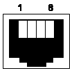
FIGURE D-1 Ethernet RJ-45 Socket 10/100BASE-T

TABLE D-1 Ethernet RJ-45 Pin Description
|
Pin No.
|
Description
|
Color
|
|
1
|
TX +
|
White with orange
|
|
2
|
TX -
|
Orange
|
|
3
|
RX +
|
White with green
|
|
4
|
Not connected
|
Blue
|
|
5
|
Not connected
|
White with blue
|
|
6
|
RX -
|
Green
|
|
7
|
Not connected
|
White with brown
|
|
8
|
Not connected
|
Brown
|
D.2 DB9 COM Port
The COM port is a female DB9 connector that requires a male DB9 null modem cable.
FIGURE D-2 RS-232 DB9 (EIA/TIA 574) View of the Male End

TABLE D-2 Pin Names
|
Pin No.
|
Name
|
Description
|
|
1
|
DCD
|
Data Carrier Detect
|
|
2
|
RD
|
Receive Data (also called RxD, Rx)
|
|
3
|
TD
|
Transmit Data (also called TxD, Tx)
|
|
4
|
DTR
|
Data Terminal Ready
|
|
5
|
GND
|
Ground
|
|
6
|
DSR
|
Data Set Ready
|
|
7
|
RTS
|
Request To Send
|
|
8
|
CTS
|
Clear To Send
|
|
9
|
RI
|
Ring Indicator
|
| Sun StorEdge 3000 Family Installation, Operation, and Service Manual
|
816-7300-21
|
   
|
Copyright © 2004, Sun Microsystems, Inc. All rights reserved.

