| Sun StorEdge 3000 Family Installation, Operation, and Service Manual
|
   
|
This chapter describes the front and back panel LEDs, which display the operating status of all drives and modules. Topics covered in this chapter are:
For troubleshooting flowcharts related to LEDs, see Section 8.7, Troubleshooting Flowcharts.
6.1 LEDs When The Array Is First Powered On
With the array powered on but not connected to a server, you should see the LED conditions described in TABLE 6-1.
TABLE 6-1 Front Panel LED Status When Array Is First Powered On
|
LED Location
|
LED Condition
|
|
Drive LEDs
|
Solid green, if media scan off
Blinking green, if media scan on
|
|
Chassis ear LEDs
|
Solid green
|
|
Note - Whenever media scan is running on a drive, its front-panel LED flashes green. It is normal for front-panel drive LEDs to flash green while media scan is running. Media scan is disabled by default. It can be enabled to start when the array is powered up. For more information, refer to the Sun StorEdge 3000 Family RAID Firmware User's Guide.
|
6.2 Front Panel LEDs
The drive LEDs are located between the rows of drives on the front panel, as shown in FIGURE 6-1. The system operation LEDs are located on the right ear of the chassis and shown in FIGURE 6-2.
FIGURE 6-1 Front Panel LEDs
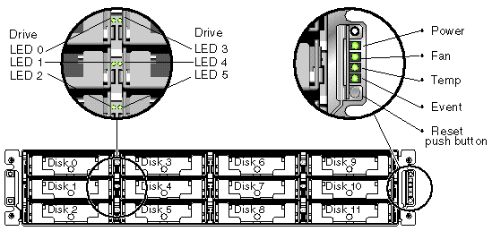
FIGURE 6-2 shows the chassis ear LEDs and reset push button. Use a paper clip to push the Reset button to silence a failed component alarm. See Section 8.2, Silencing Audible Alarms for more information about silencing audible alarms.
FIGURE 6-2 Chassis Ear LEDs and Reset Button on Front Panel
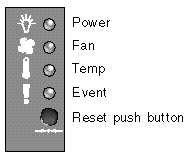
TABLE 6-2 lists the front panel LEDs and describes LED activity.
TABLE 6-2 Front Panel LEDs
|
LED
|
LED Color
|
Description
|
|
Drive
|
Solid green
|
Good: Drive power-up and spin-up OK.
|
|
Blinking green
|
Good: Indicates drive activity.
|
|
Solid amber
|
Failed: Drive failure.
|
|
Power (Light bulb icon)
Monitors the DC output voltage within tolerance specification. Overcurrent protection shutting down any voltage output is also displayed.
Voltage thresholds:
+5 VDC +/-.25 VDC
+12 VDC +/-.6 VDC
Current thresholds:
+5 VDC 35A
+12 VDC 25A
|
Solid green
|
Good: Power supply good.
|
|
Solid amber
|
Failed: One or more output voltages out of range.
|
|
Fan (Fan icon)
Monitors the fan speed within nominal operational RPM specification of 5000 RPM.
|
Solid green
|
Good: Both fans are rotating at 4000 RPM or higher.
|
|
Solid amber
|
Faulty/Failed: One or both fans is rotating at less than 4000 RPM.
|
|
Temp (Thermometer icon)
Monitors the temperature level and indicates violations of the internal temperature threshold of 131°F (55°C).
|
Solid green
|
Good: Under temperature threshold.
|
|
|
Solid amber
|
Failed: Over temperature threshold.
|
|
Event (Caution icon)
Indicates any abnormal or failure event in the I/O board.
|
Solid green
|
Normal operation of I/O board.
|
|
Solid amber
|
Failed I/O board.
|
|
Blinking amber
|
Indicates that the version of the SES firmware or associated hardware PLD code on one controller does not match that on the other controller.
|
|
Note - To test that the LEDs work, using a paper clip, press and hold the Reset button for five seconds. All the LEDs should change from green to amber when you perform this test. Any LED that fails to light indicates a problem with the LED. When you release the Reset button, the LEDs return to their initial state.
|
6.2.1 Drive LED Status
The drive LED color changes based on array events. For example, when a media scan is performed, to indicate an event is taking place, the drive LEDs blink green for the physical drives that compose the logical drive that is being scanned. The following table lists the events that influence the drive LED status.
TABLE 6-3 Drive LED Status
|
LED Status
|
Event
|
Description
|
|
Solid green
|
No error
|
A drive is working as expected.
|
|
Blinking green
|
Media scan
|
A logical drive is created, or the controller is reset, and media scan is enabled.
|
|
Blinking green
|
Drive activity
|
A drive is processing I/O.
|
|
Amber
|
Drive fault
|
A drive fails.
|
|
Amber
|
Identify
|
The Sun StorEdge CLI set led command is run, or the firmware application, "Flash All SCSI Drives" option is used.
|
|
Note - The media scan feature sequentially checks each physical drive in a selected logical drive, block by block, for bad blocks. When media scan is running on a drive, its front-panel LED flashes green. By default, media scan is disabled. You can run media scan on a logical drive manually, or set media scan to always run when you power up the array. For more information about the media scan feature, refer to the Sun StorEdge 3000 Family RAID Firmware User's Guide.
|
6.2.2 Correcting SES or PLD Firmware Version Conflicts
When you replace an I/O controller, the new controller might have a version of SES or PLD firmware different from the other controller in your array. If this mismatch occurs, when you install a controller you hear an audible alarm and see a blinking amber event LED, and an SES event message is sent.
A similar situation occurs when you add an expansion unit or JBOD and there is a mismatch between the SES or PLD firmware of the RAID array and that of the expansion unit, or between two expansion units.
See Section 7.4.4, Upgrading SES and PLD Firmware for information about upgrading SES and PLD firmware.
6.3 Back Panel LEDs
The back panel LED colors indicate the conditions described in the following figures and tables.
|
Note - To test that the LEDs work, using a paper clip, press and hold the Reset button for five seconds. All the LEDs should change from green to amber when you perform this test. Any LED that fails to light indicates a problem with the LED. When you release the Reset button, the LEDs return to their initial state.
|
6.3.1 I/O Controller Module and Battery Module LEDs
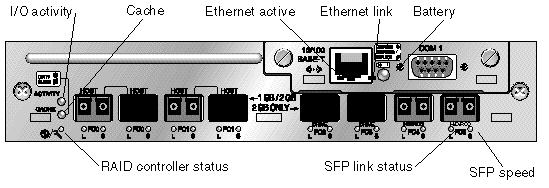
FIGURE 6-3 shows the Sun StorEdge 3510 FC Array I/O controller module and the LEDs on its back panel. FIGURE 6-4 shows the Sun StorEdge 3511 SATA Array I/O controller module and the LEDs on its back panel.
FIGURE 6-3 Sun StorEdge 3510 FC Array I/O Controller Module and Battery Module LEDs
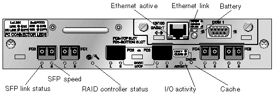
FIGURE 6-4 Sun StorEdge 3511 SATA Array I/O Controller Module and Battery Module LEDs
|
Note - Although an amber light on the back panel often indicates a faulty component, a steady amber light on the Ethernet link LED indicates normal Ethernet activity. See TABLE 6-4 for more information.
|
The I/O controller module and battery module LEDs and their color definitions are shown in TABLE 6-4.
TABLE 6-4 I/O Controller Module and Battery Module LEDs
|
LED
|
Purpose
|
LED Color Description
|
|
Battery
|
Status of battery
|
Solid green - Battery charged
Blinking green - Battery charging
Solid amber - Battery failed or missing
|
|
I/O Activity
|
I/O activity of host and disk ports
|
Off - Not busy (no I/O activity)
Blinking green - Busy (active I/O)
|
|
Cache
|
Status of memory cache
|
Off - Clean cache
Blinking green - Dirty cache; data is in memory and is not written to disk yet
|
|
Ethernet link
(active controller)
|
Status of Ethernet link
|
Solid amber - Active link
Off - Inactive connection
|
|
Ethernet link
(inactive controller)
|
Status of Ethernet link
|
Off - Active connection on inactive controller, or inactive connection
|
|
Ethernet active
|
Status of Ethernet activity
|
Blinking green - Busy
|
|
RAID controller status
|
Status of controller on I/O controller module
|
Blinking green - Good (primary controller)
Solid green - Good (secondary controller)
Solid amber - Failed RAID controller or I/O module
|
|
SFP link status (L)
|
SFP link status
|
Solid green - Active good FC Connection
Off - Empty, no FC connection, or failed FC connection
|
|
SFP speed (S)
|
SFP speed
|
Solid green - 2 Gbit
Off - 1 Gbit
|
|
Note - The batteries in controller FRUs experience discharge during shipment and might require an extended charging cycle upon initial power-up. Nominal battery operation is achieved when the battery status LED changes from amber to flashing green within 25 minutes after the initial power cycle. If the battery status LED remains amber for more than 25 minutes after the initial power-up, then the unit must be power cycled to initiate the extended charging cycle. If the battery status LED remains amber for more than 30 minutes after initiating the extended charging cycle, contact Sun service personnel for additional instructions.
|
Ethernet link LEDs on Sun StorEdge 3510 FC arrays and Sun StorEdge 3511 SATA arrays differ from the Ethernet link LEDs found on Sun StorEdge 3310 SCSI arrays and Sun StorEdge 3320 SCSI arrays. On Sun StorEdge 3510 FC arrays and Sun StorEdge 3511 SATA arrays, a connected port's Ethernet link LED glows solid amber only on the active controller, because the Ethernet port on an FC array is considered active only if its controller is active. On an inactive controller, a port's Ethernet link LED is off whether the port is connected or not. The absence of a solid amber light on a connected port's Ethernet link LED indicates that this controller is not the active controller.
6.3.2 I/O Expansion Module LEDs
FIGURE 6-5 and FIGURE 6-6 show I/O expansion modules and their LEDs for the Sun StorEdge 3510 FC expansion unit and the Sun StorEdge 3511 SATA expansion unit.
FIGURE 6-5 I/O Expansion Module for a Sun StorEdge 3510 FC Expansion Unit

FIGURE 6-6 I/O Expansion Module for a Sun StorEdge 3511 SATA Expansion Unit

The I/O expansion module LEDs and their color definitions are shown in TABLE 6-5.
TABLE 6-5 I/O Expansion Module LEDs
|
LED
|
Purpose
|
LED Color Description
|
|
I/O Activity
|
I/O activity of host and disk ports
|
Off - Not busy (no I/O activity)
Blinking green - Busy (active I/O)
|
|
I/O module status
|
Status of I/O module
|
Solid green - Power-up successful and SES chip has successfully read on-board temperature and voltage sensors
Amber - Expansion unit powering up, or failed voltage or temperature sensor
Off - Expansion unit is not powered up
|
|
SFP link status (L)
|
SFP link status
|
Solid green - Active good FC Connection
Off - Empty, no FC connection, or failed FC connection
|
|
SFP speed (S)
|
SFP speed
|
Solid green - 2 Gbit
Off - 1 Gbit
|
6.3.3 Power Supply and Fan Module LED
FIGURE 6-7 and FIGURE 6-8 show the AC and DC power supply and fan modules and their LEDs.
FIGURE 6-7 AC Power Supply and Fan Module
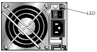
FIGURE 6-8 DC Power Supply and Fan Module
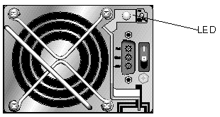
TABLE 6-6 describes the power supply and fan module LED.
TABLE 6-6 Power Supply and Fan Module LED
|
LED Purpose
|
LED Color
|
Description
|
|
Monitors the DC output voltage within tolerance specification. Overcurrent protection shutting down any voltage output is also displayed.
Voltage thresholds:
+5 VDC +/-.25 VDC
+12 VDC +/-.6 VDC
Current thresholds:
+5 VDC 35A
+12 VDC 25A
|
Solid green
Solid amber
|
Good: Power supply and fans are good.
Failed: One or more output voltages out of range or one or both fans is rotating at less than 4000 RPM.
|
| Sun StorEdge 3000 Family Installation, Operation, and Service Manual
|
816-7300-21
|
   
|
Copyright © 2004, Sun Microsystems, Inc. All rights reserved.


