| A P P E N D I X B |
|
Monitoring JBODs |
This appendix explains how to enable and monitor a standalone JBOD. Note that not all of the array functionality is supported for JBODs. Procedures covered in this appendix include the following:
|
To monitor peripheral device condition and events of a JBOD, you first need to enable JBOD support.
1. Choose View  Agent Options Management.
If you are not already logged in as ssconfig or ssadmin, a password prompt is displayed; type the password. The Agent Options Management window is displayed.
2. Select the Enable JBOD Support check box.
3. To immediately display the JBOD in the main window, you need to probe for new inventory. Choose View  View Server and click Probe.
The JBOD is displayed in the main window.
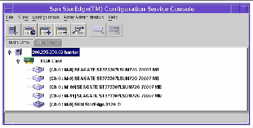
In a single-bus configuration, both ports of the JBOD are connected to one HBA on the server, as shown in the following example.

In a split-bus configuration, each port is connected to its own HBA, as shown in the following example. A SAF-TE limitation prevents the main window from showing the drives connected to port A and port B. The program can only monitor the JBOD from the server connected to port B as shown in the following example.

| Note - In a split-bus configuration, if each port is connected to different servers, the program can only monitor the JBOD from the server connected to port B. |
|
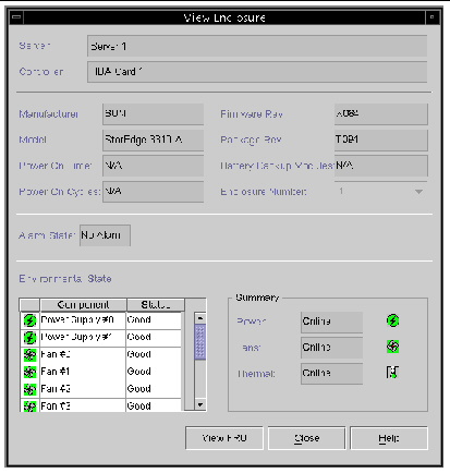
The View Enclosure window displays the component and alarm characteristics of a JBOD. When a JBOD is in a state that requires attention, a device status state symbol is displayed on the JBOD device in the main window. See Device Status for a description of the symbols.
1. Select the enclosure icon for the Sun StorEdge 3120 SCSI array.
2. Choose View  View Enclosure.
To display FRU ID information, click View FRU.

The Environmental State section of the View Enclosure window reports the status of power supplies, fans, and temperature. It provides an overall environmental status of the array as well as the status of the individual components. For a description of the Component/Status list, see Environmental State.
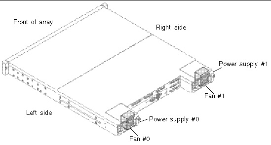
The following illustration identifies the location of the power supplies and fans in the Sun StorEdge 3120 SCSI array.

FIGURE B-1 Sun StorEdge 3120 SCSI Array Power Supply and Fan Location
Monitoring temperature at different points within the array is one of the most important SAF-TE functions. High temperatures can cause significant damage if they go unnoticed. There are a number of different sensors at key points in the enclosure. The following table shows the location of each of those sensors, which corresponds to the Temperature # displayed in the View Enclosure Component/Status list.
|
For instructions on how to download firmware to disk drives for the Solaris host, refer to the README file in the patch that contains the firmware. For patch information, refer to the release notes for your array.
|
Drive failure places the JBOD in a critical state. A red device status symbol  is displayed on the JBOD device in the main window. After replacing a failed drive, perform the following steps to discover the drive.
The following steps describe how to discover the replaced drive on systems running the Solaris OS.
1. If the drive comes back online automatically (that is, the red device status symbol is dismissed), run the command:
3. If the drive does not come back online automatically (that is, the red device status symbol is not dismissed), perform a reconfiguration reboot by running the command:
The following steps describe how to discover the replaced drive on systems running the Linux OS.
3. In the dmesg output, look for a line similar to "Detected scsi disk sdX at scsi<controller>, id <channel>, lun <target>" where the X in sdX is the disk number.
4. To create the device entries in /dev, run the command:
Where the X in sdX is the disk number.
5. Proceed to fdisk, format, and create a file system.
The following steps describe how to discover the replaced drive on a Microsoft Windows OS.
1. Install the new drive according to the instructions in the Sun StorEdge 3000 Family Installation, Operation, and Service Manual for your array.
2. Select View  View Server, and click Rescan.
3. To verify that the program recognizes the new drive, select it on the main window.
4. Select View  View Physical Drive, and verify the information.
The following steps describe how to discover the replaced drive on systems running the HP-UX OS.
2. Select View  View Server, and click Rescan.
3. To verify that the program recognizes the new drive, select it on the main window.
4. Select View  View Physical Drive, and verify the information.
5. If the drive is still not seen, the host might need to be rebooted. Run the commands:
The following steps describe how to discover the replaced drive on systems running the IBM AIX OS.
| Note - You must have superuser privileges to run the commands necessary to replace a failed drive. |
1. Create the logical drive and map its LUN to the correct host channel.
Output similar to the following is displayed.
4. If any of the drives show “none,” you need to assign a Physical Volume IDENTIFIER.
c. Select Change/Show Characteristics of a Disk.
d. Select the disk without a PVID.
e. Select ASSIGN physical volume identifier, press Tab once to display Yes for the value, and press Return.
f. Press Return again to confirm and repeat Step a-Step f as necessary.
6. From the smitty main menu, select System Storage Management (Physical & Logical Storage)  Logical Volume Manager
  Volume Groups
  Add a Volume Group.
7. Specify a name for the volume group, make sure the partitions for the journaled file system are large enough, and select the Physical Volume Name(s).
8. From the smitty main menu, select System Storage Management (Physical & Logical Storage)  File Systems
  Add / Change / Show / Delete File Systems
  (Enhanced) Journaled File System.
9. Select the volume group and set the field.
Copyright © 2009 Sun Microsystems, Inc. All rights reserved.