| A P P E N D I X A |
|
|
This appendix describes how to configure single path connections between a data host running Solaris 10 operating system and a Sun StorageTek 2530 Array, with a focus on the requirements of the configuration on the Solaris 10 operating system.
This appendix consists of the following sections:
The Sun StorageTek 2530 arrays supports single path connections with the operating systems listed in TABLE 8. Note the required Solaris patches.
|
Note - Solaris 9 and Sun Cluster 3.x are not supported for single path connections. |
Key requirements to configuring Solaris SAS single path are:
Before configuring single path, you need to collect host, initiator, and topology information, review the naming conventions, and prepare a table of configuration information as outlined in the following sections.
Follow the procedures in the following order to ensure smooth operations:
|
1. Issue the hostname command to collect the host information.
# hostname
csqa221-163
# hostname
csqa221-168
This example uses two data hosts running Solaris 10 OS.
|
1. Issue the dmesg command to collect initiator information. (The initiator of data on the HBA.)
# dmesg | grep WWN
Apr 9 17:02:26 csqa221-163 mpt1: Port 0/PHYs 0-3 (wide-port) WWN: 0x500605b000253410
Apr 9 17:02:26 csqa221-163 mpt1: Port 1/PHYs 4-7 (wide-port) WWN: 0x500605b000253414
# dmesg | grep WWN
Apr 9 17:00:38 csqa221-168 mpt3: Port 0/PHYs 0-3 (wide-port) WWN: 0x500605b0000db020
Apr 9 17:00:38 csqa221-168 mpt3: Port 1/PHYs 4-7 (wide-port) WWN: 0x500605b0000db024
In each of the above lines in the output is embedded valuable information as shown in the following example:
mpt3: Port 0/PHYs 0-3 (wide-port) WWN: 0x500605b0000db020
The Sun StorageTek 2540 Array, with a Fibre Channel data path, has built-in drivers with dynamic discovery and multi-pathing capabilities.
The Sun StorageTek 2530 Array, with a SAS data path, does not have these capabilities. There is no utility to correlate the connections between initiators, HBA ports and controller ports. You have to plan the topology prior to configuring single path connections.
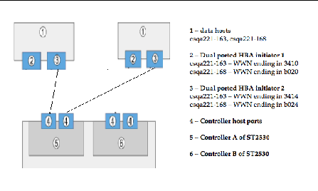
In the examples that follow, the topology is listed in FIGURE A-1
FIGURE
A-1 Topology of the 2530 array when
connected to data hosts.

For the volumes to be seen by a data host, the initiators need to be mapped correctly to the volumes. Additionally, when configuring single path connections on a data host running Solaris 10 OS, you need to make the naming modifications listed in TABLE A-1 in the Sun StorageTek Common Array Manager software to improve the operations.
Use the following table as a guideline when collecting all information prior to configuring single path connections.
With the information collected, you can now proceed to make the connections and configure the software for single path connections as documented in the following sections:
This appendix consists of the following sections:
|
1. Establish a hand shake between the host and the array
a. Physically connect the cables for your specific topology.
In the steps to follow, it is assumed that connections have been made as per the topology depicted in Figure 1.
b. Issue the following command once from each of the data hosts:
If no output displays, the command ran successfully. By executing the above command, a hand shake is established between the data host and the ST2530 array.
2. Log into the Sun StorageTek Common Array Manager software as outlined in the Sun StorageTek Common Array Manager Software Installation Guide.
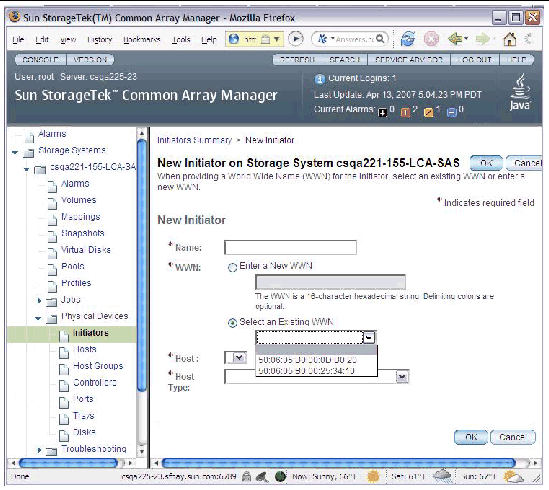
3. On the New Initiator page, view existing WWNs of initiators in Sun StorageTek Common Array Manager software as shown in FIGURE A-2.
FIGURE
A-2 WWN after Using the devfsadm Command.

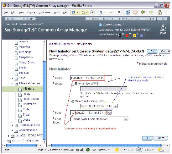
Next, follow the usual steps to configure storage in the Sun StorageTek Common Array Manager software. However. you must follow the naming conventions outlined in Naming Modifications to Make in the Sun StorageTek Common Array Manager Software.
For more information, review the online help, especially the "Planning for Volume Creation" topic.
Review the following configuration notes:
FIGURE
A-3 Creating New Initiators

Before the host can see more devices, identify the target ID and update the /kernel/drv/sd.conf file as noted in the following sections:
|
1. Ensure that LUN ID 0 is mapped to a data host correctly as requested in Configuration Notes.
2. Identify the HBA controller in the output of the dmesg command issued in To Collect Host Information.
In this example, it is HBA controller 3, listed as mpt3.
# dmesg | grep WWN
Apr 13 19:26:54 csqa221-168 mpt3: Port 0/PHYs 0-3 (wide-port) WWN: 0x500605b0000db020
Apr 13 19:26:54 csqa221-168 mpt3: Port 1/PHYs 4-7 (wide-port) WWN: 0x500605b0000db024
3. Correlate the controller with the target and lun.
In the format command output, for each controller, identify the target id and the lun. (The controller in the prior example, mpt3 is equivalent to c3 below.)
In the example below, for controller 3 (c3t9d0), the target id is 9 and the lun is 0. You will use this information to update the sd.conf file.
# format
Searching for disks...done
c3t9d0: configured with capacity of 40.00GB
AVAILABLE DISK SELECTIONS:
0. c0t0d0 <SUN72G cyl 14087 alt 2 hd 24 sec 424>
/pci@1f,700000/pci@0/pci@2/pci@0/pci@8/LSILogic,sas@1/sd@0,0
1. c0t1d0 <SUN72G cyl 14087 alt 2 hd 24 sec 424>
/pci@1f,700000/pci@0/pci@2/pci@0/pci@8/LSILogic,sas@1/sd@1,0
2. c3t9d0 <SUN-LCSM100_S-0617 cyl 20478 alt 2 hd 64 sec 64>
/pci@1f,700000/pci@0/pci@9/LSILogic,sas@0/sd@9,0
|
1. Add a line for each lun to see volumes from the array as shown in the following example. Add only the volumes you intend to use. Adding all volumes will increase the boot time.
#
name="sd" parent="mpt" target=9 lun=0;
name="sd" parent="mpt" target=9 lun=1;
name="sd" parent="mpt" target=9 lun=2;
name="sd" parent="mpt" target=9 lun=3;
[ .. ]
name="sd" parent="mpt" target=9 lun=30;
|
Note - LUN 31 (the UTM LUN) cannot be used. Do not add it to the sd.conf file. |
2. Reboot the array to place the changes to sd.conf file into effect.
# reboot -- -r
After reboot, you should be able to see the volumes.
3. Before using the volumes, you must label the disks using the format command.
4. After labeling the disk, verify the labels by looking at the detailed partition table using the format verify option.
If you get an error when attempting to write the label and/or when you are trying to write to a device specifically in a dual controller configuration, it is likely that the LUN is currently owned by the controller that the host is not connected to.
If this happens, go to the Volume Details Page for the volume associated with this LUN and change the owner as noted in FIGURE A-4.
FIGURE
A-4 Changing Volume Ownership on the
Volume Details Page.

Take the following steps to ensure smooth continuation of operations when replacing controllers.
On Solaris 10 OS, the target id is generated by using the World Wide Names of both the HBA initiators and the controller ports. When replacing controllers, there is a very high possibility that the target id will change. Therefore, caution must be exercised when replacing controllers.
Prior to replacing the controller, note how and where the devices are being used. Typically, a system administrator will either use the devices as raw devices or create file systems on them. When a file system is created, the mount point information is typically placed in the /etc/vfstab file.
|
1. After replacing the controller, follow the steps to identify the new target id in To Identify the Target ID and To Update the /kernel/drv/sd.conf File.
2. Make changes
to /etc/vfstab and any other
places to reflect the change in the target
id.
Copyright © 2007, Sun Microsystems, Inc. All Rights Reserved.