Messaging Server Example
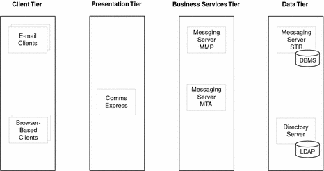
The following figure shows a basic logical architecture for a deployment of Messaging Server. This logical architecture shows only the logically distinct components required for Messaging Server. Later figures illustrate the relationships among these components.
Note –
Typically, a deployment of Messaging Server is part of an enterprise solution that includes other Java Enterprise System components, as illustrated in Identity-Based Communications Example.
Figure 4–4 Logical Architecture for Messaging Server Deployment

The following table describes the components depicted in Messaging Server Example.
Table 4–5 Components in Messaging Server Logical Architecture|
Component |
Description |
|---|---|
|
Email clients |
Client applications for reading and sending email. |
|
Messaging Server configured as a message transfer agent (MTA) to receive, route, transport, and deliver email messages. |
|
|
Messaging Server configured as a message multiplexor (MMP) to route connections to appropriate message stores for retrieval and storage. MMP accesses Directory Server to look up directory information to determine the proper message store. |
|
|
Messaging Server configured as a message store for retrieval and storage of email messages. |
|
|
Provides access to LDAP directory data. |
The logical architecture does not specify replication of services for the Messaging Server components. For example, enterprise deployments typically create separate inbound and outbound MTA instances but Messaging Server Example shows only one MTA component. The replication of logical components into multiple instances is a design decision that you make during the deployment design phase.
Messaging Server Use Cases
Use cases help identify the relationships among the logical components in an architecture. By mapping the interactions between the components according to the use cases, you get a visual picture of component interaction that is helpful in deployment design.
Typically, you analyze each use case to determine the interaction of components prior to deployment design. The following three use cases are typical for Messaging Server and show interactions among the logical components.
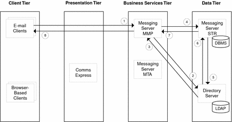
 Use Case 1: User Logs in Successfully to Messaging Server
-
Email client sends login information to Messaging Server Multiplexor (MMP)
-
MMP requests verification of user ID and password from Directory Server.
-
Directory Server returns verification to MMP.
-
MMP requests message list from Messaging Server Message Store (STR).
-
STR requests user’s LDAP record from Directory Server.
-
Directory Server returns user’s LDAP record to STR.
-
STR returns message list to MMP.
-
MMP forwards message list to email client.

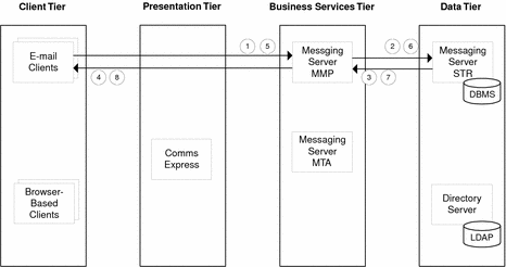
 Use Case 2: Logged-In User Reads and Deletes Mail
-
Email client requests message to read from Messaging Server Multiplexor (MMP).
-
MMP requests message from Messaging Server Message Store (STR).
-
STR returns message to MMP.
-
MMP forward message to email client.
-
Email client sends deletes message action to MMP.
-
MMP forwards delete message action to STR.
-
STR deletes message from database and sends confirmation to MMP.
-
MMP forwards delete confirmation to email client.

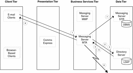
 Use Case 3: Logged-In User Sends Email Message
-
Email client sends message composed in client to Messaging Server Message Transfer Agent (MTA).
-
MTA requests verification of user ID and password from Directory Server.
-
Directory Server returns verification to MTA.
-
MTA checks Directory Server for the destination domain for each recipient.
-
Directory Server returns to MTA the destination domain for each recipient.
-
MTA forwards message to each recipient.
-
MTA forwards message to Messaging Server Message Store (STR) to store message in outbox.
-
MTA sends confirmation to email client.

- © 2010, Oracle Corporation and/or its affiliates
