Example Logical Architectures
This section provides some examples of logical architectures for Java Enterprise System solutions. These examples show how you place logical components within the appropriate tiers of a multitiered architecture and then analyze the relationships between the components by studying the use cases. Use the logical architectures examples in this section as a basis for understanding logical architecture design in Java Enterprise System solutions.
The first example is a basic Messaging Server solution that illustrates how the logically distinct components of Messaging Server interact with other components. The second example shows a logical architecture for an identity-based deployment solution that might be appropriate for a medium-sized enterprise of about 1,000 to 5,000 employees.
Messaging Server Example
The following figure shows a basic logical architecture for a deployment of Messaging Server. This logical architecture shows only the logically distinct components required for Messaging Server. Later figures illustrate the relationships among these components.
Note –
Typically, a deployment of Messaging Server is part of an enterprise solution that includes other Java Enterprise System components, as illustrated in Identity-Based Communications Example.
Figure 4–4 Logical Architecture for Messaging Server Deployment
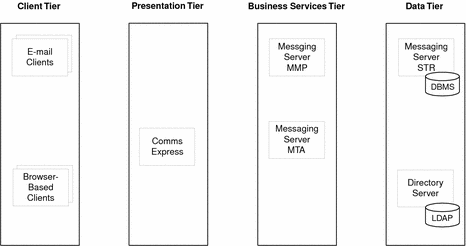
The following table describes the components depicted in Messaging Server Example.
Table 4–5 Components in Messaging Server Logical Architecture|
Component |
Description |
|---|---|
|
Email clients |
Client applications for reading and sending email. |
|
Messaging Server configured as a message transfer agent (MTA) to receive, route, transport, and deliver email messages. |
|
|
Messaging Server configured as a message multiplexor (MMP) to route connections to appropriate message stores for retrieval and storage. MMP accesses Directory Server to look up directory information to determine the proper message store. |
|
|
Messaging Server configured as a message store for retrieval and storage of email messages. |
|
|
Provides access to LDAP directory data. |
The logical architecture does not specify replication of services for the Messaging Server components. For example, enterprise deployments typically create separate inbound and outbound MTA instances but Messaging Server Example shows only one MTA component. The replication of logical components into multiple instances is a design decision that you make during the deployment design phase.
Messaging Server Use Cases
Use cases help identify the relationships among the logical components in an architecture. By mapping the interactions between the components according to the use cases, you get a visual picture of component interaction that is helpful in deployment design.
Typically, you analyze each use case to determine the interaction of components prior to deployment design. The following three use cases are typical for Messaging Server and show interactions among the logical components.
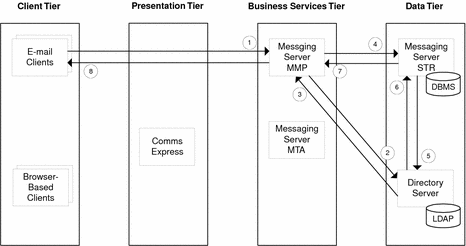
 Use Case 1: User Logs in Successfully to Messaging Server
-
Email client sends login information to Messaging Server Multiplexor (MMP)
-
MMP requests verification of user ID and password from Directory Server.
-
Directory Server returns verification to MMP.
-
MMP requests message list from Messaging Server Message Store (STR).
-
STR requests user’s LDAP record from Directory Server.
-
Directory Server returns user’s LDAP record to STR.
-
STR returns message list to MMP.
-
MMP forwards message list to email client.
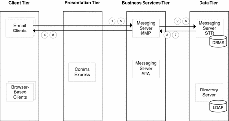
 Use Case 2: Logged-In User Reads and Deletes Mail
-
Email client requests message to read from Messaging Server Multiplexor (MMP).
-
MMP requests message from Messaging Server Message Store (STR).
-
STR returns message to MMP.
-
MMP forward message to email client.
-
Email client sends deletes message action to MMP.
-
MMP forwards delete message action to STR.
-
STR deletes message from database and sends confirmation to MMP.
-
MMP forwards delete confirmation to email client.
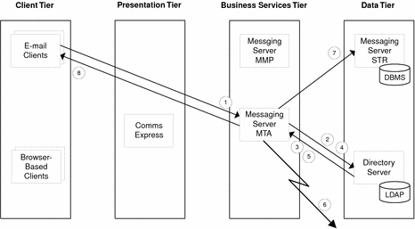
 Use Case 3: Logged-In User Sends Email Message
-
Email client sends message composed in client to Messaging Server Message Transfer Agent (MTA).
-
MTA requests verification of user ID and password from Directory Server.
-
Directory Server returns verification to MTA.
-
MTA checks Directory Server for the destination domain for each recipient.
-
Directory Server returns to MTA the destination domain for each recipient.
-
MTA forwards message to each recipient.
-
MTA forwards message to Messaging Server Message Store (STR) to store message in outbox.
-
MTA sends confirmation to email client.
Identity-Based Communications Example
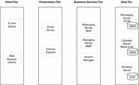
This example illustrates an identity-based communications solution for a medium-sized enterprise of about 1,000 to 5,000 employees. Typically, an exhaustive business analysis followed by detailed technical requirements analysis is needed to design the logical architecture. However, because this is a theoretical example, assume that the following business requirements have been determined:
-
Employees of the enterprise require personalized access to internal web sites, communications services, calendar services, and other resources.
-
Enterprise-wide authentication and authorization provide access to the internal web sites and other services.
-
Single identity is tracked across all enterprise services, enabling a single sign-on (SSO) that provides access to the internal websites and other services.
Use cases for this example would detail login procedures, reading email, sending email, personalizing the portal, synchronizing calendars, and other similar user activities.
The following figure shows a logical architecture for this type of identity-based communications solution.
Use Cases for Identity-Based Communications Example
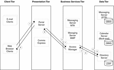
For a deployment solution of this nature, there typically are numerous detailed use cases outlining the user interaction with the services provided by the solution. This example focuses on the interaction among components when a user logs into a portal from a web browser client. The example splits this login scenario into two use cases:
-
User logs in, becomes authenticated, and Portal Server retrieves the user’s portal configuration.
-
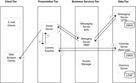
Portal Server retrieves email and calendar information to display in the web client.
The two use cases can be considered one extended use case. However, for this example, the use cases are separated for simplicity.
 Use Case 1: User Logs in Successfully and Portal Retrieves
User’s Configuration
-
Web browser client sends user ID and password to Portal Server.
-
Portal Server requests authentication from Access Manager.
-
Access Manager requests verification of user ID and password from Directory Server.
-
Directory Server verifies user ID and password.
-
Access Manager requests user profile from Directory Server.
-
Directory Server returns user profile.
-
Portal Server requests user display profile from Access Manager.
-
Access Manager returns portal configuration.
-
Portal configuration is displayed in web browser client.
 Use Case 2: Portal Server Displays Email and Calendar Information
-
After successful log in, authentication, and retrieval of portal configuration, Portal Server requests email messages from Messaging Server MMP.
-
MMP requests message list from Messaging Server STR.
-
STR returns message list to MMP.
-
MMP forwards message headers to Portal Server.
-
Portal Server requests calender information from Communications Express.
-
Communications Express requests calendar information from Calendar Server backend.
-
Calendar Server backend returns calendar information to Communications Express.
-
Communications Express forwards calendar information to Portal Server.
-
Portal Server sends all channel information to web browser client.
- © 2010, Oracle Corporation and/or its affiliates
