| A P P E N D I X D |
|
Universal Rail Kit Installation |
This appendix describes how to install the Sun Storage 6580 or 6780 controller tray and expansion trays into an existing cabinet. Use the universal rail kit to mount the trays into any of these cabinets:
Unpack the universal rail kit and check the contents.
The universal rail kit (part number 594-2489-02) contains the following items:
| Note - Typically, the main and extender pieces of both the left and right rails are shipped pre-assembled. |
The mounting hardware required for each rack or cabinet type is listed in the following table:
*For cabinet installations with M5 or 12-24 threaded cabinet rails, the following screws are not supplied. You must acquire these to match the threading requirements of your cabinet rails:
**For cabinet installations with unthreaded cabinet rails, the following hardware is not supplied. You must acquire these to match the requirements of your cabinet rails:
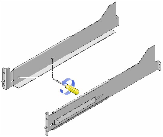
Use the #2 Phillips screwdriver to loosen the two rail adjustment screws on each rail to allow adjustment of each rail length (FIGURE D-1).
FIGURE D-1 Loosening the Rail Screws to Adjust the Controller Tray Rail Length
Use the #2 Phillips screwdriver to loosen the four rail adjustment screws on each rail to allow adjustment of each rail length (FIGURE D-2).
FIGURE D-2 Loosening the Rail Screws to Adjust the Expansion Tray Rail Length
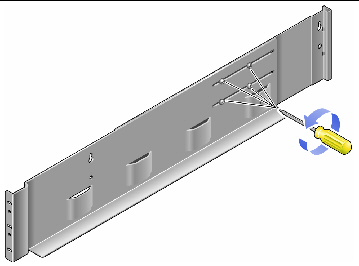
| Note - The expansion tray rails are preconfigured to adjust to cabinet rail depths of between 26.18 inches (664.97 mm) and 28.93 inches (734.82 mm). For cabinet rail depths outside of this range, remove and reposition the four rail adjustment screws (FIGURE D-2) to support your required rail length. |

2. Check the contents of the box for the following items:
Select the cabinet in which you will be installing the array. Be sure the cabinet is installed as described in the installation instructions provided with it.
1. Stabilize the cabinet as described in the cabinet documentation.
2. If the cabinet has casters, make sure the casters are locked to prevent the cabinet from rolling.
3. Remove or open the top front panel.
4. Remove or open the vented back panel.
The procedure in this section describes how to attach the rails for a standard 19-inch cabinet with threaded cabinet rails. Depending on your cabinet, the specific steps you need to follow may vary.
To attach the rails to a cabinet with threaded cabinet rails:
1. Follow these steps first for the left rail and then for the right rail:
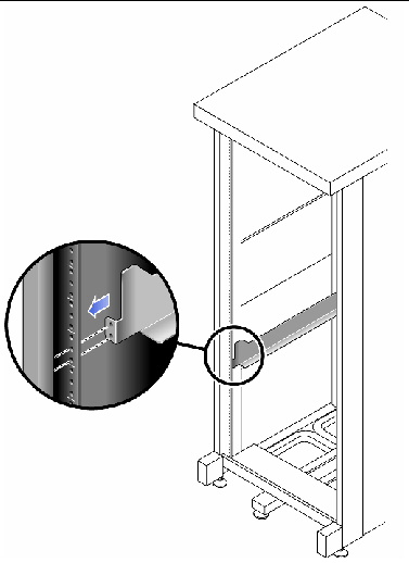
c. Position the front of the rail directly inside the front cabinet rail (FIGURE D-3).
Make sure that you feed the back rail pin through the appropriate hole.
FIGURE D-3 Positioning the Front of the Left Rail Behind the Left Front Cabinet Rail
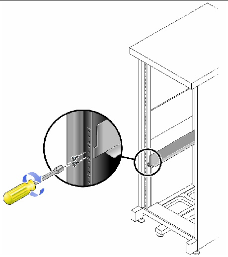
d. Use the #2 Phillips screwdriver to insert and tighten the two screws to secure the left rail to the front of the cabinet (FIGURE D-4).
Put the screws into the bottom two holes only. You will secure the third screw after inserting the tray.
The controller tray requires four standard mounting units (4RU) of vertical space in the cabinet. Each standard mounting unit (U) has three mounting holes in the left and right cabinet rails. Insert the screws into the lowest two holes of the 4RU slot in which the tray is to be mounted.
These screws pass through the cabinet rail holes and screw into threaded holes in the rail. Do not tighten the front screws until you have begun securing the back rail screws.
When first positioning the rails, observe that the top of the rail ear (brace) is 1.25 inches below the top of where the tray will be positioned.
FIGURE D-4 Securing the Left Rail to the Front of the Cabinet
e. At the back of the cabinet, adjust the length of the rail to position it directly inside the cabinet rail (FIGURE D-5).
Be sure to align the rail flange so that the mounting holes at the back correspond to those at the front of the cabinet.
FIGURE D-5 Adjusting the Length of the Left Rail at the Back of the Cabinet
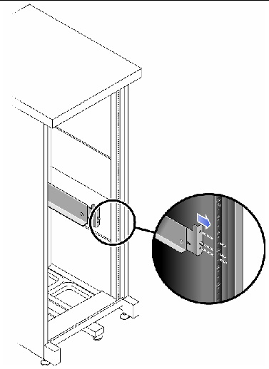
f. Use the #2 Phillips screwdriver to insert and tighten the three screws at the back of the rail (FIGURE D-6).
FIGURE D-6 Securing the Left Rail to the Back of the Cabinet
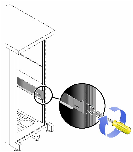
2. Use the #2 Phillips screwdriver to tighten the adjustment screws at the back of each rail (FIGURE D-7).
FIGURE D-7 Tightening the Rail Adjustment Screws
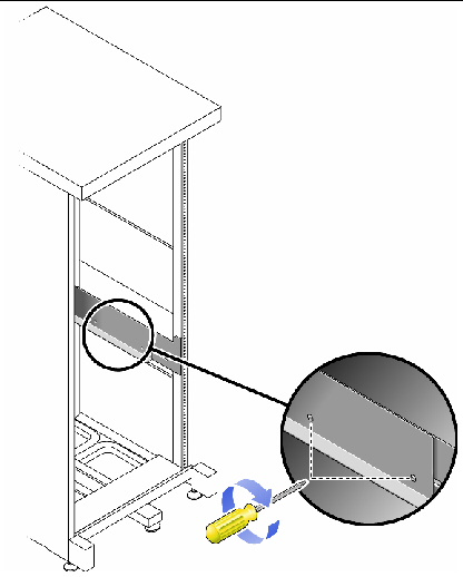
Install the controller tray in the fifth slot up from the bottom of the cabinet, where you have attached the rails.
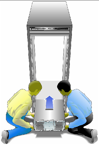
1. Using two people, one at each side of the tray, carefully lift and rest the tray on the bottom ledge of the left and right rails (FIGURE D-8).

|
Caution - Use care to avoid injury. A tray can weigh up to 95 pounds (45 kg). Use two people to lift the tray. |
FIGURE D-8 Positioning the Controller Tray in the Cabinet Rack Slot 5
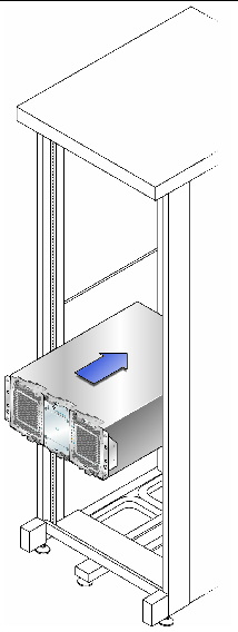
2. Carefully slide the tray into the cabinet until the front flanges of the tray touch the vertical face of the cabinet (FIGURE D-9).
FIGURE D-9 Sliding the Tray Into the Cabinet
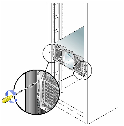
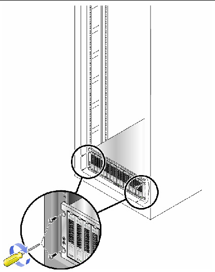
3. Use the #2 Phillips screwdriver to install and tighten the third rail screw on each side, securing the tray to the cabinet and rail.
FIGURE D-10 Securing the Tray to the Front of a Cabinet
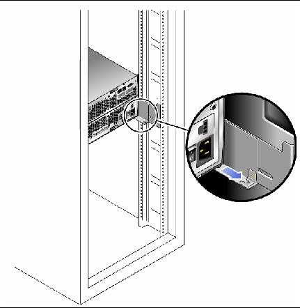
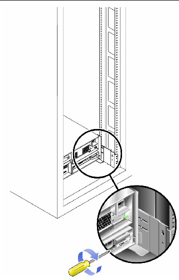
4. Install and tighten the screw on each side of the back of the tray to secure the tray to the cabinet (FIGURE D-11).
FIGURE D-11 Securing the Tray to the Back of the Cabinet Rail
You will install the expansion trays beneath the controller tray in the first empty RU slot at the bottom of the cabinet. If you are installing additional expansion trays, continue installing the trays from the bottom up.
Depending on the type of cabinet in which you will install the expansion tray, use one of the following procedures to attach the rails:
This procedure describes the steps to attach the universal rail kit to:
To attach the universal rail kit to a Sun Rack cabinet or a cabinet with M5 or 12-24 threaded cabinet rails:
1. Follow these steps first for the left and then for the right rail:
a. Position the front of the rail directly inside the front cabinet rail (FIGURE D-12).
FIGURE D-12 Positioning the Left Rail Behind the Left Front Cabinet Rail
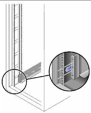
b. Use the #2 Phillips screwdriver to insert and tighten two 8-32 screws to secure the rail to the front of the cabinet (FIGURE D-13).
Each expansion tray requires three standard mounting units (3RU) of vertical space in the cabinet. Each standard mounting unit (U) has three mounting holes in the left and right cabinet rails. Insert the screws into the lowest holes in the top two mounting units of the 3RU slot in which the tray is to be mounted.
These screws pass through the cabinet rail holes and screw into threaded holes in the left rail.
FIGURE D-13 Securing the Left Rail to the Front of the Cabinet
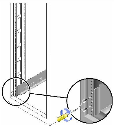
c. At the back of the cabinet, adjust the length of the rail as needed to fit the cabinet, and position the rail flange over the face of the cabinet rail (FIGURE D-14).
FIGURE D-14 Adjusting the Length of the Left Rail at the Back of the Cabinet
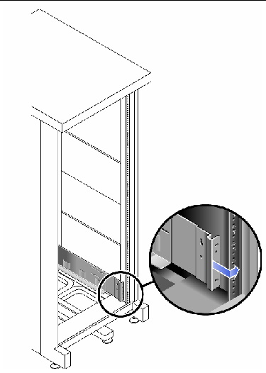
Be sure to align the rail flange so that the mounting holes at the back correspond to those at the front of the cabinet.
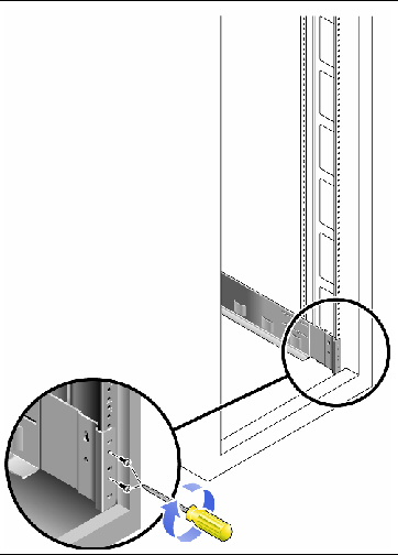
d. Depending on the type of cabinet you have, do one of the following (FIGURE D-15):
FIGURE D-15 Securing the Left Rail to the Back of the Cabinet
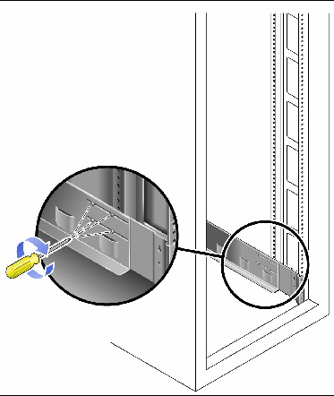
2. Using the #2 Phillips screwdriver, tighten the eight adjustment screws (four on each side) at the back of each rail (FIGURE D-16).
FIGURE D-16 Tightening the Rail Adjustment Screws
This procedure describes the steps to attach the universal rail kit to a Sun StorEdge Expansion cabinet or a Sun Fire cabinet.
To attach the universal rail kit, follow these steps first for the left rail and then for the right rail:
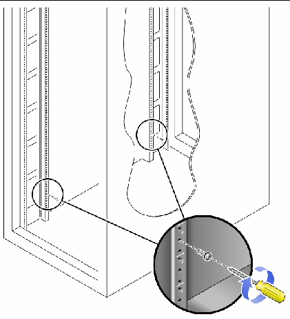
1. In each of the four inner mounting rails, insert a 10-32 screw in the center hole of the mounting unit of the 3RU slot in which the tray is to be mounted (FIGURE D-17).
Do not tighten at this time. You will hang the side rails on these screws.
FIGURE D-17 Inserting Rail Mounting Screws in Middle Holes of the Upper Mounting Unit of the Mounting Slot
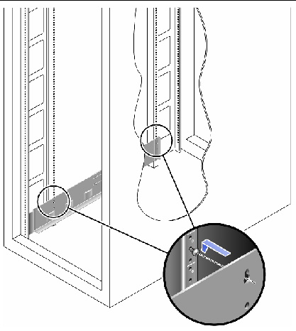
2. Hang the rail by aligning the large slots of the rail over the front and back screws and then pulling the rail down so that each screw is at the top of the slot (FIGURE D-18).
3. Adjust the length of the rail to fit the cabinet.
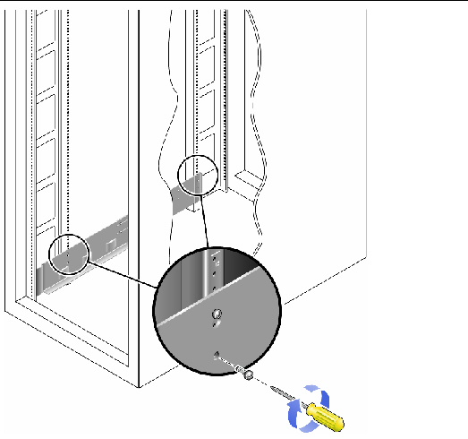
4. Using the #2 Phillips screwdriver, insert two 10-32 screws in the lower side mounting holes for the rail (FIGURE D-19).
The hole corresponds to the center hole of the middle mounting unit of the 3RU slot in which the rail is installed.
FIGURE D-19 Inserting Screws in the Lower Side Mounting Holes of the Cabinet
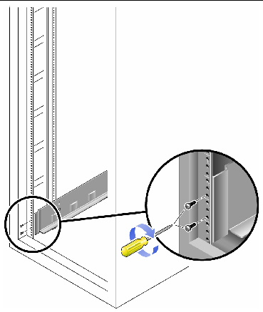
5. Use the #2 Phillips screwdriver to insert and tighten two 8-32 screws to secure the rail to the front of the cabinet (FIGURE D-20).
These screws pass through the cabinet rail holes and screw into threaded holes in the front of the rails.
Insert the screws into the lowest holes in the top two mounting units of the 3RU slot in which the tray is to be mounted.
FIGURE D-20 Securing the Rail to the Front of the Cabinet
6. Tighten all screws on the rail.
This procedure describes the steps to attach the universal rail kit to any 19-inch wide, 4-post EIA-compatible rack, or cabinet with unthreaded cabinet rails.
To attach the universal rail kit, follow these steps first for the left rail and then for the right rail:
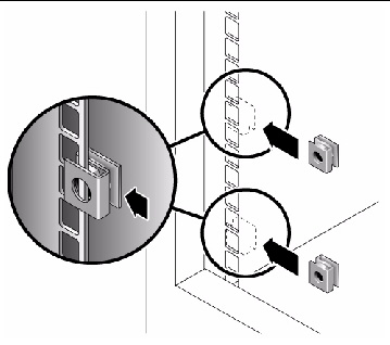
1. Snap two cage nuts over the middle holes in the upper and lower mounting units of the 3RU cabinet slot in which you will mount the tray (FIGURE D-21).
FIGURE D-21 Inserting Cage Nuts Over Rail Mounting Holes in Cabinet Rails
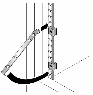
2. Hook a cabinet rail adapter plate over the front of the cabinet rail (FIGURE D-22).
Position the adapter plate over the 3RU slot in which the tray is to be mounted.
FIGURE D-22 Inserting the Cabinet Rail Adapter Plate on the Cabinet Rail
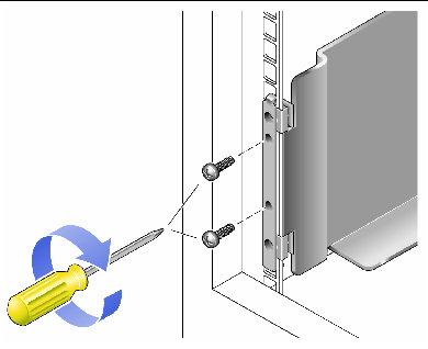
3. Use the #2 Phillips screwdriver to insert and tighten two 8-32 screws to secure the rail to the front of the cabinet (FIGURE D-23).
These screws pass through the unthreaded inner holes of the cabinet rail adapter plate and screw into the threaded holes in the front of the mounting rail.
FIGURE D-23 Securing the Rail to the Front of the Cabinet
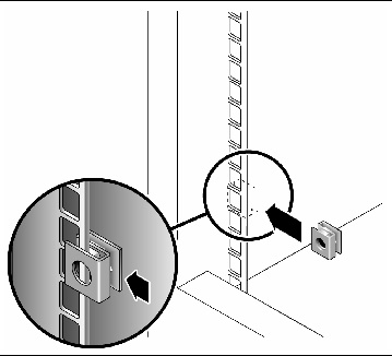
4. On the corresponding cabinet rail at the back of the cabinet, snap one cage nut over the lowest hole in the middle mounting unit of the 3RU cabinet slot in which you will mount the tray (FIGURE D-24).
FIGURE D-24 Inserting a Cage Nut on the Cabinet Rail at the Back of the Cabinet
5. At the back of the cabinet, adjust the length of the rail as needed to fit the cabinet, and position the rail flange over the face of the cabinet rail (FIGURE D-25).
FIGURE D-25 Adjusting the Length of the Rail at the Back of the Cabinet
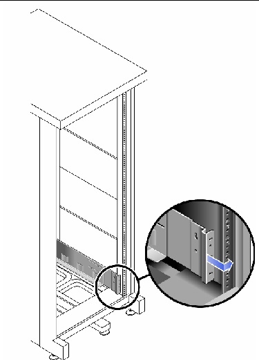
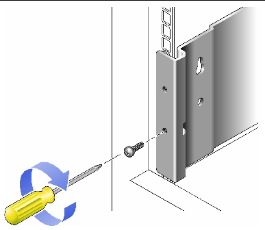
6. Insert and tighten a screw appropriate for the cage nut to secure the rail to the back cabinet rail (FIGURE D-26).
The screw passes through the lower unthreaded inner hole of the mounting rail and screws into the threaded hole of the cage nut.
FIGURE D-26 Securing the Rail to the Back of the Cabinet
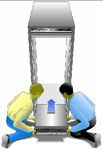
1. Using two people, one at each side of the tray, carefully lift and rest the tray on the bottom ledge of the left and right rails (FIGURE D-27).

|
Caution - Use care to avoid injury. A tray can weigh up to 95 pounds (45 kg). |
FIGURE D-27 Positioning the Tray in the Cabinet
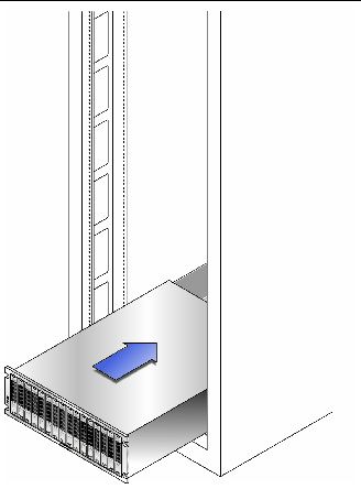
2. Carefully slide the tray into the cabinet until the front flanges of the tray touch the vertical face of the cabinet (FIGURE D-28).
FIGURE D-28 Sliding the Tray Into the Cabinet
3. Depending on the type of cabinet you have, do one of the following:
FIGURE D-29 Securing the Tray to the Front of a Cabinet
4. Install and tighten the 6-32 screw on each side of the back of the tray to secure the tray to the cabinet (FIGURE D-30).
FIGURE D-30 Securing the Tray to the Back of the Cabinet Rail
After you install the controller and expansion trays, following the cabling diagrams for your configuration in Intertray Cabling.
Copyright © 2009 Sun Microsystems, Inc. All rights reserved.