| C H A P T E R 3 |
 Installing the SPARC Enterprise M3000 Server in a Sun Rack
 |
This chapter describes how to mount an M3000 server in a Sun Rack 1000, Sun Rack 900, and Sun Rack II.
The following topics are in this chapter:

|
Caution - The M3000 server can weigh up to 23 kg (50.7 lb). Two people are required to mount the server safely in the cabinet. |
Up to twenty-one 2U M3000 servers can be mounted in the following cabinets:
The M3000 server is designed to be mounted in a standard 19-inch rack with a depth of 1000 mm or more. See Mounting Specifications.
The server is mounted in the rack using slide rail assemblies. Refer to the instructions packaged with the slide rail kit for assembling and attaching the rail kit and cable management arm (CMA) to the SPARC Enterprise M3000 server, in preparation for installing the server in the rack.

|
Caution - For stability, populate the rack with the servers at the lowest location before filling in the higher areas. |
1. Extend the anti-tilt bar or anti-tilt legs.
For details on extending the anti-tilt bar or anti-tilt legs, see Appendix B, Extending the Anti-Tilt Bar or Anti-Tilt Legs.

|
Caution - The anti-tilt bar must be extended or the rack might topple when the server is installed on the extended slide rails. |

|
Caution - For stability, populate the rack with the servers at the lowest location before filling in the higher areas. |
2. Extend the slide rails from the slide assemblies.
3. With the assistance of another person, install the chassis into the cabinet by aligning the chassis rails with the rail parts in the rack and carefully pushing in until you hear a click and the server stops.
The server will stop mid-way in the rack after the sound of the click.
4. Release the latches on the sides of the server and continue to push in the server until completely seated in the rack.
5. Tighten the thumbscrews in the chassis bezel to hold the chassis securely in the rack.
To prevent catastrophic failures, the design of your input power sources must ensure that adequate power is provided to your servers. Use dedicated AC breaker panels for all power circuits that supply power to your server. Electrical work and installations must comply with applicable local, state, or national electrical codes.
The Sun Rack 1000/900 can fit up to two modular power supplies (MPS). Each MPS is 2U. The MPS must be installed in the bottom of the cabinet.
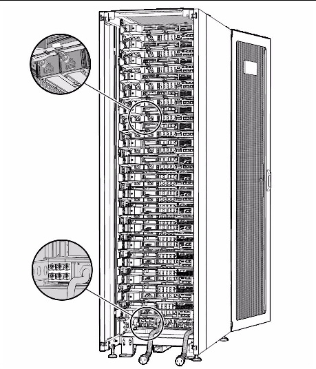
TABLE 3-2 and FIGURE 3-1 show an example of the recommended wiring configurations for the M3000 servers with one MPS.
| Note - For M3000 servers in positions twelve and above, use power cords that are 2.5m in length to reach from the servers to the MPS units. |
FIGURE 3-1 Sun Rack 1000 With M3000 Servers and One MPS

| Note - The numbering in a rack reads from bottom to top and right to left. |
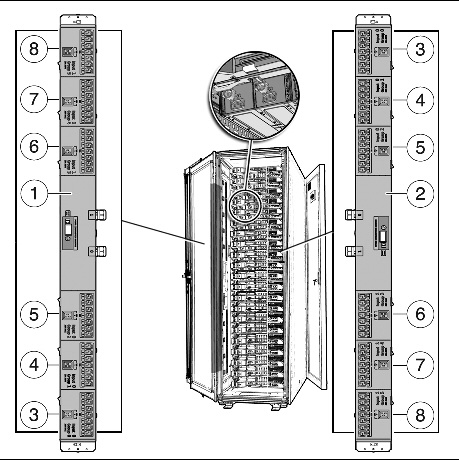
To ensure redundant power sourcing, use the recommended power wiring configurations for the M3000 server in a Sun Rack II.
Sun supports up to two PDUs in a Sun Rack II cabinet, one on either side. SPARC Enterprise M3000 servers can use PDU types 15k, 25k, or 35k. For more information on PDUs in a Sun Rack II, refer to the Sun Rack II User’s Guide.
| Note - The numbering in a rack reads from bottom to top and right to left. |
FIGURE 3-2 Sun Rack II with Twenty-One M3000 Servers and Two PDUs

Qualified equipment cabinets housing these midrange servers require their own customer-supplied circuit breaker and AC receptacle for each power cord. Provide a stable power source, such as an uninterruptible power system (UPS), to reduce the possibility of component failures. If the computer equipment is subjected to repeated power interruptions and fluctuations, it is susceptible to a higher component failure rate than it would be with a stable power source.
Both midrange servers are shipped with grounding-type (three-wire) power cords. Always connect the cords into grounded power outlets. Each power cord will also supply your server with proper earth ground. Sun has tested the equipment cabinets for radiated and conducted emissions and have determined there is no difference in emissions with or without a ground strap grounding the equipment cabinets. No additional earth grounding is necessary but it may be added if desired.
Contact your facilities manager or a qualified electrician to determine what type of power is supplied to your building.

Copyright © 2009, 2011, Oracle and/or its affiliates. All rights reserved. FUJITSU LIMITED provided technical input and review on portions of this material.