Configuring IPMP in a Logical Domains Environment
The Logical Domains 1.3 release introduces support for link-based IPMP with virtual network devices. When configuring an IPMP group with virtual network devices, configure the group to use link-based detection. If using older versions of the Logical Domains software, you can only configure probe-based detection with virtual network devices.
Configuring Virtual Network Devices Into an IPMP Group in a Logical Domain
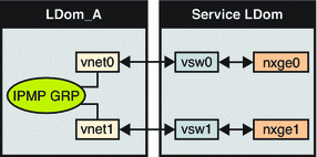
The following diagram shows two virtual networks (vnet1 and vnet2) connected to separate virtual switch instances (vsw0 and vsw1) in the service domain, which, in turn, use two different physical interfaces (nxge0 and nxge1). In the event of a physical link failure in the service domain, the virtual switch device that is bound to that physical device detects the link failure. Then, the virtual switch device propagates the failure to the corresponding virtual network device that is bound to this virtual switch. The virtual network device sends notification of this link event to the IP layer in the guest LDom_A, which results in failover to the other virtual network device in the IPMP group.
Figure 7–3 Two Virtual Networks Connected to Separate Virtual Switch Instances

Further reliability can be achieved in the logical domain by connecting each virtual network device (vnet0 and vnet1) to virtual switch instances in different service domains (as shown in the following diagram). In this case, in addition to physical network failure, LDom_A can detect virtual network failure and trigger a failover following a service domain crash or shutdown.
Figure 7–4 Each Virtual Network Device Connected to Different Service Domains

Refer to the Solaris 10 System Administration Guide: IP Services for more information about how to configure and use IPMP groups.
Configuring and Using IPMP in the Service Domain
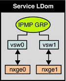
IPMP can be configured in the service domain by configuring virtual switch interfaces into a group. The following diagram shows two virtual switch instances (vsw0 and vsw1) that are bound to two different physical devices. The two virtual switch interfaces can then be plumbed and configured into an IPMP group. In the event of a physical link failure, the virtual switch device that is bound to that physical device detects the link failure. Then, the virtual switch device sends notification of this link event to the IP layer in the service domain, which results in failover to the other virtual switch device in the IPMP group.
Figure 7–5 Two Virtual Switch Interfaces Configured as Part of IPMP Group

Using Link-Based IPMP in Logical Domains Virtual Networking
With Logical Domains 1.3, the virtual network and virtual switch devices support link status updates to the network stack. By default, a virtual network device reports the status of its virtual link (its LDC to the virtual switch). This setup is enabled by default and does not require you to perform additional configuration steps.
Sometimes it might be necessary to detect physical network link state changes. For instance, if a physical device has been assigned to a virtual switch, even if the link from a virtual network device to its virtual switch device is up, the physical network link from the service domain to the external network might be down. In such a case, it might be necessary to obtain and report the physical link status to the virtual network device and its stack.
The linkprop=phys-state option can be used to configure physical link state tracking for virtual network devices as well as for virtual switch devices. When this option is enabled, the virtual device (virtual network or virtual switch) reports its link state based on the physical link state while it is plumbed as an interface in the domain. You can use standard Solaris network administration commands such as dladm and ifconfig to check the link status. See the dladm(1M) and ifconfig(1M) man pages. In addition, the link status is also logged in the /var/adm/messages file.
Note –
You can run both link-state-unaware and link-state-aware vnet and vsw drivers concurrently on a Logical Domains system. However, if you intend to configure link-based IPMP, you must install the link-state-aware driver. If you intend to enable physical link state updates, upgrade both the vnet and vsw drivers to the Solaris 10 10/09 OS, and run at least Version 1.3 of the Logical Domains Manager.
 Configure Physical Link Status Updates
This procedure shows how to enable physical link status updates for virtual network devices.
You can also enable physical link status updates for a virtual switch device by following similar steps and specifying the linkprop=phys-state option to the ldm add-vsw and ldm set-vsw commands.
Note –
You need to use the linkprop=phys-state option only if the virtual switch device itself is plumbed as an interface. If linkprop=phys-state is specified and the physical link is down, the virtual network device reports its link status as down, even if the connection to the virtual switch is up. This situation occurs because the Solaris OS does not currently provide interfaces to report two distinct link states, such as virtual-link-state and physical-link-state.
-
Become superuser or assume an equivalent role.
Roles contain authorizations and privileged commands. For more information about roles, see Configuring RBAC (Task Map) in System Administration Guide: Security Services.
-
Enable physical link status updates for the virtual device.
You can enable physical link status updates for a virtual network device in the following ways:
-
Create a virtual network device by specifying linkprop=phys-state when running the ldm add-vnet command.
Specifying the linkprop=phys-state option configures the virtual network device to obtain physical link state updates and report them to the stack.
Note –If linkprop=phys-state is specified and the physical link is down (even if the connection to the virtual switch is up), the virtual network device reports its link status as down. This situation occurs because the Solaris OS does not currently provide interfaces to report two distinct link states, such as virtual-link-state and physical-link-state.
# ldm add-vnet linkprop=phys-state if-name vswitch-name ldom
The following example enables physical link status updates for vnet0 connected to primary-vsw0 on the logical domain ldom1:
# ldm add-vnet linkprop=phys-state vnet0 primary-vsw0 ldom1
-
Modify an existing virtual network device by specifying linkprop=phys-state when running the ldm set-vnet command.
# ldm set-vnet linkprop=phys-state if-name ldom
The following example enables physical link status updates for vnet0 on the logical domain ldom1:
# ldm set-vnet linkprop=phys-state vnet0 ldom1
To disable physical link state updates, specify linkprop= by running the ldm set-vnet command.
The following example disables physical link status updates for vnet0 on the logical domain ldom1:
# ldm set-vnet linkprop= vnet0 ldom1
-
Example 7–1 Configuring Link-Based IPMP
The following examples show how to configure link-based IPMP both with and without enabling physical link status updates:
-
The following example configures two virtual network devices on a domain. Each virtual network device is connected to a separate virtual switch device on the service domain to use link-based IPMP.
Note –Test addresses are not configured on these virtual network devices. Also, you do not need to perform additional configuration when you use the ldm add-vnet command to create these virtual network devices.
The following commands add the virtual network devices to the domain. Note that because linkprop=phys-state is not specified, only the link to the virtual switch is monitored for state changes.
# ldm add-vnet vnet0 primary-vsw0 ldom1
# ldm add-vnet vnet1 primary-vsw1 ldom1
The following commands configure the virtual network devices on the guest domain and assign them to an IPMP group. Note that test addresses are not configured on these virtual network devices because link-based failure detection is being used.
# ifconfig vnet0 plumb
# ifconfig vnet1 plumb
# ifconfig vnet0 192.168.1.1/24 up
# ifconfig vnet1 192.168.1.2/24 up
# ifconfig vnet0 group ipmp0
# ifconfig vnet1 group ipmp0
-
The following example configures two virtual network devices on a domain. Each domain is connected to a separate virtual switch device on the service domain to use link-based IPMP. The virtual network devices are also configured to obtain physical link state updates.
# ldm add-vnet linkprop=phys-state vnet0 primary-vsw0 ldom1
# ldm add-vnet linkprop=phys-state vnet1 primary-vsw1 ldom1
Note –The virtual switch must have a physical network device assigned for the domain to successfully bind. If the domain is already bound and the virtual switch does not have a physical network device assigned, the ldm add-vnet commands will fail.
The following commands plumb the virtual network devices and assign them to an IPMP group:
# ifconfig vnet0 plumb
# ifconfig vnet1 plumb
# ifconfig vnet0 192.168.1.1/24 up
# ifconfig vnet1 192.168.1.2/24 up
# ifconfig vnet0 group ipmp0
# ifconfig vnet1 group ipmp0
Configuring and Using IPMP in Releases Prior to Logical Domains 1.3
In Logical Domains releases prior to 1.3, the virtual switch and the virtual network devices are not capable of performing link failure detection. In those releases, network failure detection and recovery can be set up by using probe-based IPMP.
Configuring IPMP in the Guest Domain
The virtual network devices in a guest domain can be configured into an IPMP group as shown in Figure 7–3 and Figure 7–4. The only difference is that probe-based failure detection is used by configuring test addresses on the virtual network devices. See System Administration Guide: IP Services for more information about configuring probe-based IPMP.
Configuring IPMP in the Service Domain
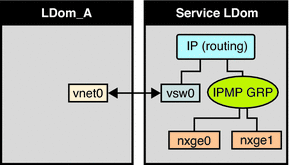
In Logical Domains releases prior to 1.3, the virtual switch device is not capable of physical link failure detection. In such cases, network failure detection and recovery can be set up by configuring the physical interfaces in the service domain into an IPMP group. To do this, configure the virtual switch in the service domain without assigning a physical network device to it. Namely, do not specify a value for the net-dev (net-dev=) property while you use the ldm add-vswitch command to create the virtual switch. Plumb the virtual switch interface in the service domain and configure the service domain itself to act as an IP router. Refer to the Solaris 10 System Administration Guide: IP Services for information on setting up IP routing.
Once configured, the virtual switch sends all packets originating from virtual networks (and destined for an external machine) to its IP layer, instead of sending the packets directly by means of the physical device. In the event of a physical interface failure, the IP layer detects failure and automatically re-routes packets through the secondary interface.
Since the physical interfaces are directly being configured into an IPMP group, the group can be set up for either link-based or probe-based detection. The following diagram shows two network interfaces (nxge0 and nxge1) configured as part of an IPMP group. The virtual switch instance (vsw0) has been plumbed as a network device to send packets to its IP layer.
Figure 7–6 Two Network Interfaces Configured as Part of IPMP Group

 Configure a Host Route for Probe-Based IPMP
Note –
This procedure only applies to guest domains and to releases prior to 1.3, where only probe-based IPMP is supported.
If no explicit route is configured for a router in the network corresponding to the IPMP interfaces, then one or more explicit host routes to target systems need to be configured for the IPMP probe-based detection to work as expected. Otherwise, probe detection can fail to detect the network failures.
-
Configure a host route.
# route add -host destination-IP gateway-IP -static
For example:
# route add -host 192.168.102.1 192.168.102.1 -static
Refer to Configuring Target Systems in System Administration Guide: IP Services for more information.
- © 2010, Oracle Corporation and/or its affiliates
