Chapter 4 Updating the Flash PROM on the Ultra 1, Ultra 2, Ultra 450, and Sun Enterprise 450 Systems
The steps in this chapter describe how to update the flash PROM on the Ultra(TM) 1, Ultra 2, Ultra 450, and the Sun(TM) Enterprise(TM) 450 systems.
Some systems will need to be updated to a higher level of OpenBoot(TM) firmware in the flash PROM before they can run the 64-bit mode of the Solaris(TM) 7 operating environment. The OpenBoot firmware is contained within a single flash PROM for the Ultra 1, Ultra 2, Ultra 450, and the Sun Enterprise 450 systems.
Note -
Only those systems identified in this chapter and the following chapter need the flash PROM upgrade.
The flash PROM devices, which contain OpenBoot, are electrically erasable and writable devices. This means that the firmware can be updated without removing the flash PROM from the system board.
Related Material
You can also use the Flash PROM Update Multimedia Collection containing videos of how to upgrade the Flash PROM in the Ultra 1, Ultra 2, Ultra 450, and Sun Enterprise 450 systems. This collection is located on the Flash PROM Update Multimedia AnswerBook CD. For more information, see "Flash PROM Update Multimedia Collection".
Determining If the Flash PROM Needs Updating
Only sun4u systems that can run the 64-bit mode of the Solaris 7 operating environment might need the flash PROM update. Systems that can only run the 32-bit mode (such as those in the sun4c, sun4d, and sun4m platform groups) do not require updated firmware to run Solaris 7 software.
Note -
If the Solaris 7 operating environment notified you that the flash PROM in your system needs updating, skip the steps in the procedure "To Determine If Your System Requires a Flash PROM Update" and go directly to "Updating the Flash PROM".
To Determine If Your System Requires a Flash PROM Update
-
Determine the architecture type of your system.
% uname -m
Table 4-1 Determining the System ArchitectureIf your system architecture type is . . .
Then . . .
o sun4u
Go to Step 2.
o sun4c, sun4d, sun4m
You do not need a flash PROM update. Do not proceed further.
-
Determine the system type of your system.
% uname -i
Table 4-2 Determining the System TypeIf your system type is one of the following systems. . .
Then . . .
SUNW, Ultra-1
SUNW, Ultra-2
SUNW, Ultra-4
SUNW, Ultra-Enterprise
Go to Step 3 for each system type.
Not in the above list
You do not need a flash PROM update. Do not proceed further.
-
Determine the version level of the firmware in your system. Type:
% prtconf -V
Table 4-3 Determining the Firmware Version LevelIf your system type is . . .
And you see a number lower than . . .
Then . . .
Otherwise . . .
SUNW, Ultra-1
3.11.1
Proceed to "Updating the Flash PROM".
You do not need a flash PROM update. Do not proceed further.
SUNW, Ultra-2
3.11.2
Proceed to "Updating the Flash PROM".
You do not need a flash PROM update. Do not proceed further.
SUNW, Ultra-4
3.7.107
Proceed to "Updating the Flash PROM".
You do not need a flash PROM update. Do not proceed further.
SUNW, Ultra-Enterprise
3.2.16
Proceed to Chapter 5, Updating the Flash PROM on the Sun Enterprise 3x00, 4x00, 5x00, and 6x00 Systems.
You do not need a flash PROM update. Do not proceed further.
Updating the Flash PROM
This section describes the following:
-
Capturing configuration variable settings
-
Installing the Solaris 7 operating environment
-
Making the flash PROM write-enabled
-
Steps to perform before updating the flash PROM
-
Updating the flash PROM
Note -For step-by-step instructions, follow the procedures beginning with "To Capture the Configuration Variable Settings".
After installing the Solaris 7 operating environment, on your hardware set the write-protect/enable flash PROM jumper to the write-enable position (Sun Ultra 1 and Ultra 2 systems) before you attempt to update the firmware in the flash PROM. To change the write protection state of the Sun Enterprise 450 system, turn the external front panel keyswitch.
Refer to the recovery procedure covered later in this chapter if there is a power interruption during the update process.
Return the write-protect/enable jumper (Sun Ultra 1 and Ultra 2 systems) to the write-protect position after updating the firmware in the flash PROM.
When your system has been updated to the proper firmware revision, you can run the Solaris 7 software in 64-bit mode.
Capturing Configuration Variable Settings
While the Solaris operating environment is still running, capture the NVRAM configuration variable settings before you install the Solaris 7 operating environment or begin the flash PROM update process. This will enable you to restore customized settings if there is a problem during the flash PROM upgrade.
To Capture the Configuration Variable Settings
-
Using the eeprom utility, capture the system's configuration variable settings in a file. The filename is any file name you choose.
% eeprom > filename
Note -If you have custom values installed in oem-logo or keymap, those values cannot be displayed or printed properly by the eeprom utility because the contents contain binary information. If it is necessary to restore these values after a power loss, you should determine the original method by which these values were placed into NVRAM and use that method to restore the values.
-
Print out the values captured by the eeprom command. You must have a printed copy of the configuration values before you install the Solaris 7 operating environment and begin to update the flash PROM. Type the following:
lp filename
To Install the Solaris 7 Operating Environment
-
Install the Solaris 7 operating environment on your system.
Refer to the Installation Library shipped in your Solaris 7 media kit. As the Solaris 7 operating environment is installed, you will be notified whether the flash PROM in your system needs updating. Installing this Solaris release will provide the software that can upgrade your system's flash PROM to the required level.
Making the Flash PROM Write-Enabled
Before you update the OpenBoot firmware contained in the flash PROM, you must set a jumper to the write-enable position (Sun Ultra 1 and Ultra 2 systems) or set the front panel keyswitch to the proper position (Sun Enterprise 450 system and the Sun Ultra 450 workstation).
The Sun Ultra 1 and Ultra 2 systems, which do not have a front panel keyswitch, are equipped with jumpers on their motherboards that allow the flash PROM to be either write-protected or write-enabled. The default position as shipped from the factory is for the flash PROM to be write-protected. In order for the flash PROM to be updated, you must change the jumper to the write-enable position.
Sun Ultra 1 and Ultra 2 Systems: To Change the Jumper to the Write-Enable Position
-
Shut down the system. Type the following:
% su
Type your superuser password
# init 0
System shutdown messages
-
Power off the system unit.
Refer to the installation guide or service manual for your system.
-
Remove the system access cover.
Refer to the installation guide or service manual for your system for this procedure.
-
Use proper grounding procedures such as wearing a wrist strap to avoid electrostatically damaging system components.
Refer to the installation guide or service manual for your system for this procedure.
-
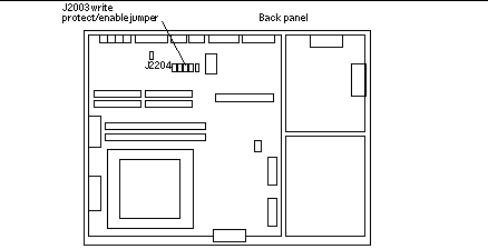
Locate the flash PROM J2003 write-protect/enable jumper on the motherboard in your system:
-
See Figure 4-1 if you have a Sun Ultra 1 Series system.
-
See Figure 4-2 if you have a Sun Ultra 1 Creator Series system.
-
See Figure 4-3 if you have a Sun Ultra 2 system.
You may have to remove a plug-in card if the card is covering the flash PROM jumper. Refer to your service manual for your system to remove the card.
Figure 4-1 Sun Ultra 1 Series Write-Protect/Enable Jumper Location on Motherboard
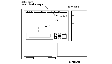
Figure 4-2 Sun Ultra 1 Creator Series Write-Protect/Enable Jumper Location on Motherboard
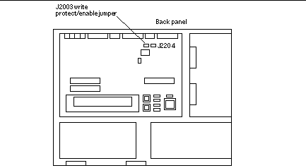
Figure 4-3 Sun Ultra 2 System Write-Protect/Enable Jumper Location on Motherboard
-
-
Set the J2003 write-protect/enable jumper to pins 2 and 3 jumpered (write enabled) using needlenose pliers (see Figure 4-4). Pin 1 is noted by an asterisk (*).
Figure 4-4 Setting the Write-Protect/Enable Jumper to the Write-Enable Position
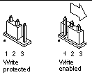 Table 4-4 Jumper Setting
Jumper
Pins 1 + 2 Jumpered
Pins 2 + 3 Jumpered
Default Jumper on Pins
Name
J2003
Write-protect
Write-enable
1 + 2
Write-protect/enable
-
If you removed a plug-in card from the system before changing the jumper, replace the card now.
-
Remove your wrist strap and replace the system access cover.
Refer to the installation guide or service manual for your system for this procedure.
Sun Enterprise 450 System and the Sun Ultra 450 Workstation: Disabling Write Protection
For the Sun Enterprise 450 system and the Sun Ultra 450 workstation you do not have to change jumper pins. Instead, you move the keyswitch to allow the flash PROM to be write-enabled.
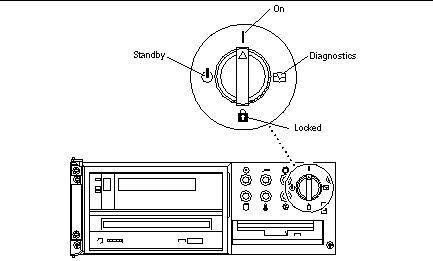
When the switch is set to the Locked position (Figure 4-5), the flash PROM is write-protected. When the switch is set to the On or Diagnostics position, the flash PROM is write-enabled.
To Write Enable the Flash PROM on the Sun Enterprise 450 System and the Sun Ultra 450 Workstation
-
Turn the keyswitch to the On or Diagnostics position (Figure 4-5) before updating the flash PROM.
Note -Disabling write-protection the Sun Enterprise 450 system or the Ultra 450 workstation assumes that the write-protect/enable jumper was set in the default position (enabled). If you previously changed the write-protect/enable jumper to be write protected, perform the steps to make the flash PROM write enabled in "Location of Flash PROM Jumpers in Sun Enterprise 450 System and the Ultra 450 Workstation". You must change the jumper to be write enabled before continuing with the flash PROM update procedure.
Figure 4-5 Sun Enterprise 450 and Sun Ultra 450 Keyswitch Location
Before Updating the Flash PROM
Before you begin updating the flash PROM, please note the following.
Do not interrupt power during flash PROM updating. When you are using the update routine, do not remove or insert system boards.
Note -
If power is interrupted during flash PROM updating, follow the power interruption recovery procedures covered later in this chapter.
Running the Flash PROM Update Script Manually
The flash PROM update script is typically run at bootup. You can also run the flash PROM update script manually by doing the following:
-
If you shut down the system in order to set the write-enable jumper (Sun Ultra 1 and Ultra 2 systems), turn the system on so it can boot.
-
Bring the system down to single user mode.
% su
Type your superuser password
# init S
Type the following: -
Execute the flash PROM update script by typing the following:
/bin/sh /usr/platform/sun4u/lib/prom/`/usr/bin/uname -i`
Follow the step-by-step instructions when running the script in the section "To Update the Flash PROM". Begin with Step 2 (do not execute the reboot command).
To Update the Flash PROM
-
If you shut down your system to set the write-enable jumper (Ultra 1, Ultra 2 systems), turn the system on so it can boot. Go to Step 1.
-
If you did not need to shut down the system (for example, with the Sun Enterprise 450 system or the Sun Ultra 450 workstation), reboot your system. Type reboot at the superuser prompt.
# reboot
-
If your flash PROM needs to be updated, the flash PROM update script displays the following message
This system has older firmware. Although the current firmware is fully capable of running the 32-bit packages, you will not be able to run the 64-bit packages installed on this system until you update the system flash PROM.

This system ships with flash PROM write-protect jumpers in the "write disabled" position. Before running the flash PROM update, please verify that the flash PROM jumpers are in the "write-enabled" position.

See the Hardware Platform Guide for more information.

Please answer the next question within 90 seconds, or press the ENTER key to disable the timer.

Would you like to run the system flash PROM update now?
(By default the system flash PROM update will not be run now.) yes or no? [y,n] y

Flash Update 2.0: Program and system initialization in progress...
-
If you see the line Current Flash PROM Revision on your screen, go to Step 1. If you see the error message Flash Update: System Security is set, complete Step 1. If the Open Boot security-mode was set to either full or command, then you have PROM-level security turned on and you cannot update the flash PROM. With security turned on you will see the following error message. You need to set the security-mode variable to none.
**ERROR:  System
security is set:
System firmware was not modified.
-
If you need to change the OpenBoot security-mode, as the system boots go to the ok prompt by one of the following methods. Then follow the steps in the screen which follows.
-
Press Stop-a from the keyboard.
-
If you are running on a terminal and connected to serial port A of the system, press the Break key.
-
If you are connected to serial port A via telnet connection send a Break sequence by pressing the Control and ] keys simultaneously. This returns you to the telnet command line. Type send brk at the telnet command line.
-
If you are connected to serial port A via a tip connection, send a Break sequence by typing the characters ~# in quick succession.
Type boot, go (continue), or login (command mode)
> login
Firmware Password: Type your security password
Type help for more information
ok setenv security-mode none
ok boot
-
-
When the flash update process begins, it displays the current and available OpenBoot firmware revisions. Type yes to the question about updating the firmware in the system flash PROM. If the NVRAM configuration variable use-nvramrc? is set to true, the update script resets use-nvramrc? to false. You will only see the message about the use-nvramrc? variable if use-nvramrc? is set to true.
Current System Flash PROM Revision:
-----------------------------------
OBP 3.5.2 1997/01/06 17:40

Available System Flash PROM Revision:
-------------------------------------
OBP 3.11.1 1997/12/03 15:44

NOTE: The system will be rebooted (reset) after the firmware has been updated.

Do you wish to update the firmware in the system Flash PROM? yes/no :yes

The NVRAM variable 'use-nvramrc?' was 'true'. This program will reset it to the default value 'false'. This is being done because the contents of the NVRAM variable 'nvramrc' may or may not be appropriate for use with the new firmware. Do not change the value of 'use-nvramrc?' until you evaluate the contents of 'nvramrc'.
-
Next, the update script asks you if you want to continue. Type yes. Also, if any of the NVRAM configuration variables have been customized, the update displays both the default value and the current value.
Are you sure that you wish to continue? yes/no :yes

**IMPORTANT**  If the power fails during the firmware update that is about to take place, it is possible that the customized values in the NVRAM configuration variables will revert back to their *default values* once the system power is restored. *If* this event occurs then it could have a significant effect on the behavior of the system after power is restored. Following is a list of the system's NVRAM configuration variables which have default values and have been customized. You may wish to write this information down so that the values may be restored after recovery from a power loss.

Name: sbus-probe-list
Default: 01
Current: 10
Name: nvramrc
Default: <null>
Current: ." This is a sample message which indicates that nvramrc has been modified." cr
-
The update script asks you again if you want to continue. Type yes. If the default value of any variable changed from the old revision to the new revision and you have a customized value, the update script lists the old default value, the customized value, and the new default value. If you did not print the contents of NVRAM with the eeprom utility at the beginning of the flash update process, then you may want to write down your customized value. Note that the new firmware default value will replace the customized value and the old default value.
Are you sure that you wish to continue? yes/no :yes

Note this change to the default value for NVRAM variable 'sbus-probe-list'
The default value for the old firmware: '01'
Your customized value in NVRAM:         '10'
The default value for the new firmware: 'e01'
The new firmware default value is replacing your custom value *and* the old default value in NVRAM. This change *will* have an effect on the system after the system has been reset.
Note -After the update, you may wish to evaluate if the customized values displayed on the previous screen need to be modified.
-
If the jumper is not set so that the flash PROM can be written to or the keyswitch is set to the locked position, you will see the following error message. To remedy the problem, make the flash PROM write-enabled.
Couldn't determine the flash PROM component type.
-
On the Sun Ultra 1 and Ultra 2 systems, halt the system by typing init 0 at the superuser prompt. Power off the system. Set the J2003 jumper to be write enabled (pins 2 and 3 jumpered). Then, power on the system and complete the flash PROM update process. For more details, see the section "Making the Flash PROM Write-Enabled".
-
On the Sun Enterprise 450 system or the Sun Ultra 450 workstation, turn the keyswitch to the On or Diagnostics position then type reboot at the # prompt.
-
-
At this point, the flash PROM is updated. After the update, the system reboots if the update completed successfully or unsuccessfully.
Erasing the top half of the Flash PROM.
Programming OBP into the top half of the Flash PROM.
Verifying OBP in the top half of the Flash PROM.

Erasing the bottom half of the Flash PROM.
Programming OBP into the bottom half of Flash PROM.
Verifying OBP in the bottom half of the Flash PROM.

Erasing the top half of the Flash PROM.
Programming POST into the top half of Flash PROM.
Verifying POST in the top half of the Flash PROM.

The system's Flash PROM firmware has been updated.

Please wait while the system is rebooted . . .
The system's reboot messages are displayed.
-
At this point any NVRAM configuration variable that had a customized value will be restored except use-nvramrc? and the customized values displayed in Step 1. You will see messages similar to the following:
rebooting...
Resetting ...
Restoring previous NVRAM environment settings...
#power-cycles =       376
security-#badlogins =  5
nvramrc <custom nvramrc>
OK
Resetting ...
Note -You may see variables listed above that were not shown earlier in the process when the customized values were displayed. This is because some of the variables shown above may not have assigned default values.
-
If you changed the write-enable jumper settings on Sun Ultra 1 or Ultra 2 systems earlier, change the jumper back to the write-protect position (see Figure 4-1, Figure 4-2, Figure 4-3, and Table 4-4.)
-
Allow the system to boot so you can become superuser.
-
Halt the system by typing init 0 at the superuser prompt.
-
Power off the system.
-
Open the system unit (refer to the installation or service manual for your system).
-
Attach a wrist strap properly (refer to the installation or service manual for your system).
-
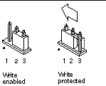
Reset the J2003 write-enable/protect jumper to the write-protect position. In the write-protect position pins 1 and 2 are jumpered (see Figure 4-1, Figure 4-2, Figure 4-3, Figure 4-6, and Table 4-4). You may need to remove a plug-in card from the system before resetting the jumper if the card is covering the jumper. Pin 1 is noted by an asterisk (*).
Figure 4-6 Moving the Write-Protect/Enable Jumper Back to the Write-Protect Position
-
If you removed a plug-in card from the system before changing the jumper, replace the card now.
Refer to the installation guide or service manual for your system for this procedure.
-
Remove your wrist strap and replace the system access cover.
Refer to the installation guide or service manual for your system for this procedure.
-
Turn the power on to the system.
-
-
If you have a Sun Enterprise 450 system or a Sun Ultra 450 workstation, after the flash PROM update is completed, turn the keyswitch to the Standby position, wait a few seconds, and then power on again.
This power-cycling flushes any old firmware code out of system memory.
Recovering From a Power Failure During the Flash PROM Update
If the power was lost during the flash PROM update, complete the power interruption recovery procedure for your system.
Sun Ultra 1 and Ultra 2 Systems, Sun Enterprise 450 System, Sun Ultra 450 Workstation
If power to your system was interrupted during updating of the flash PROM, complete the following steps:
-
Turn the power switch to the Standby position to prevent power surge to the system when power is restored.
-
After power is restored to the system location, return the power switch to the On position.
After power is restored, one of the following two recovery scenarios should happen on your system. Follow the instructions described for the appropriate scenario.
Scenario 1--System Recovers After Power Restoration
If your system attempts to autoboot after power is restored, you must complete the flash PROM updating process. Complete the section "Running the Flash PROM Update Script Manually".
Scenario 2--System Does Not Recover After Power Restoration
If your system does not boot, run diagnostics, or return to the PROM monitor's ok prompt after power is restored, complete the following steps:
-
If the update was being run via a serial port and the system also has a frame buffer and keyboard installed, or if the system has a keyboard and more than one frame buffer installed:
-
Connect a monitor to each frame buffer.
-
Confirm that output has been redirected to one of the frame buffers.
-
The NVRAM configuration variables might have been modified because of the firmware update just before power was lost. If this happened, then the system output was possibly redirected to a device other than the one originally used to display it. This could only have happened if a keyboard was connected to the system.
-
If there is no keyboard connected to the system and the NVRAM configuration variables are set to their default values, then system input and output are directed to serial port A.
-
-
-
If output cannot be found on any of the installed frame buffers or serial port A, set the boot control jumper to boot from the half of the PROM that is not currently selected. See Figure 4-1 Figure 4-2, Figure 4-3, Figure 4-7, and Figure 4-8. An asterisk (*) on the main logic board notes the location of pin 1.
-
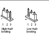
If the jumper is set for high-half booting, move it to low-half booting (pins 2 and 3 jumpered). See Figure 4-7.
-
If the jumper is set for low-half booting, move it to high-half booting (pins 1 and 2 jumpered). See Figure 4-7.
System
Jumper
Pins 1 + 2 Jumpered
Pins 2 + 3 Jumpered
Default Jumper on Pins
Name
Ultra 1, 2
J2204
High-half booting
Low-half booting
2 + 3
Boot control
Sun Enterprise 450 or Sun Ultra 450 workstation
J5501
High-half booting
Low-half booting
2 + 3
Boot control
Figure 4-7 Setting the Boot Control Jumper to Low-Half Booting or High-Half Booting
-
-
Power on the system unit.
-
If the system recovers, complete the programming process by rebooting. Complete the steps in the section "Running the Flash PROM Update Script Manually".
-
If the system does not recover, repeat Step 1 and Step 2 a second time.
-
-
If the system still does not recover, contact your Sun service provider or local Sun service Authorized Service Provider.
Restoring NVRAM Configuration Variables
If for any reason, the flash PROM update process did not complete successfully, for example if you lost power, you may have to restore diag-switch? to its default value of false and restore any customized values to the other NVRAM configuration variables.
Note -
Use the steps in this section only if for any reason your NVRAM configuration variables were not reset to their customized values or if diag-switch? was not set to its proper value.
-
Reboot the system by typing reboot at the prompt. If diag-switch? was set to true and the system is power cycled, diagnostics will be run. Running diagnostics could take several minutes. Also, the system will attempt to boot from the network once the diagnostics have completed running.
Note -Other NVRAM variables may be reset to their default values, which could affect the system in other ways. For example, if you ran the flash PROM update through the serial port and the system still has its keyboard plugged in, you will no longer get any response from the serial port connection. The firmware will be waiting for input from the keyboard.
-
As the system boots, go to the ok prompt by one of the following methods.
-
Press Stop-a from the keyboard.
-
If you are running on a terminal and connected to serial port A of the system, press the Break key.
-
If you are connected to serial port A via telnet connection send a Break sequence by pressing the Control and ] keys simultaneously. This returns you to the telnet command line. Type send brk at the telnet command line.
-
If you are connected to serial port A via a tip connection, send a Break sequence by typing the characters ~# in quick succession.
-
-
Reset the configuration variables default value to the current value (see the values you captured with the eeprom command in "To Capture the Configuration Variable Settings" and the values you wrote down earlier in this procedure in Step 1). At the ok prompt, type the following for each configuration variable:
ok setenv variablename currentvalue
ok setenv auto-boot? false
The setenv command resets each configuration variable you entered to the current value.
-
If the OpenBoot diag-switch? variable was set to true (false is the default). and the system is power cycled, diagnostics will run. Also, when you boot the system, the system will attempt to boot from the network. Unless you had diag-switch? set to true before the flash PROM update, set diag-switch? to false, the default value:
ok setenv diag-switch? false
-
If the use-nvramrc? configuration variable was set to true before the flash PROM update, as part of the update the use-nvramrc? variable was set to false because the contents of the NVRAM configuration variable nvramrc may or may not be appropriate for use with the new firmware. If you want to change the use-nvramrc? variable back to true, evaluate the contents of nvramrc first with printenv nvramrc then change the use-nvramrc? configuration variable back to true with the setenv use-nvramrc? true command.
-
Make sure that other configuration variables are set properly.
-
Use the printenv OpenBoot command to display the NVRAM configuration variables and their settings.
-
At the PROM monitor's ok prompt, you can use OpenBoot commands to restore the values of the configuration variables. Refer to the OpenBoot 3.x Command Reference Manual. You can also use the eeprom utility as superuser in the Solaris operating environment. See the eeprom man page description for more information.
-
-
If you have a Sun Enterprise 450 or an Ultra 450, turn the keyswitch to the Standby position, wait a few seconds, and then power on again. If you have an Ultra 1 or Ultra 2 system, type reset-all.
If you set the auto-boot? NVRAM configuration variable to true, and the boot-device variable contains the device or device alias where the Solaris 7 operating environment was installed, then the system will boot the Solaris 7 operating environment.
Error Messages
Most of the error messages were documented within the flash PROM update procedure. This section contains error messages that were not part of the flash PROM update procedure.
Retained Page/mmap Failure
If you see an error message similar to the following, just after the flash update program logs on Flash Update 2.0: Program and system initialization in progress... eeprom:(attach) No retained page found in device tree then the update will fail with the following message if the Flash PROM Update is attempted:
Do you wish to update the firmware in the system Flash PROM? yes/no : yes
eeprom:(mmap) on retained page failed: no retained page found
Flash Update: MMAP call failed.
: No such device or address
If this error occurs, issue a reboot command at the superuser prompt and allow the system to return to the Flash PROM Update inquiry WITHOUT INTERRUPTION. Attempt the flash PROM Update once again by completing the steps in the section "To Update the Flash PROM". If the reboot was uninterrupted and the flash PROM Update fails a second time for the same reason, contact your Authorized Service Provider.
Location of Flash PROM Jumpers in Sun Enterprise 450 System and the Ultra 450 Workstation
The flash PROM update procedure for the Sun Enterprise 450 and the Ultra 450 systems assumes that the write-protect/enable jumper was set in the default position (enabled). In order to update the flash PROM, you must move the write-protect/enable jumper to the write-enable position.
Three jumpers on the main logic board affect flash PROM operation. Figure 4-8 shows the jumper locations, and Table 4-6 describes their functions.
Figure 4-8 Flash PROM Jumpers on the Sun Enterprise 450 System and the Sun Ultra 450 Workstation
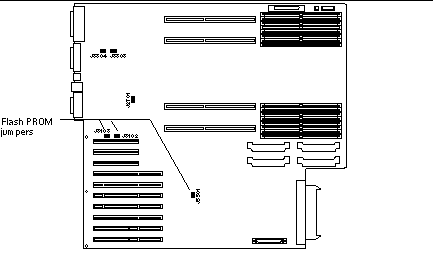 Table 4-6 Sun Enterprose 450 and Ultra 450 Flash
PROM Jumper Settings
Table 4-6 Sun Enterprose 450 and Ultra 450 Flash
PROM Jumper Settings|
Jumper |
Pins 1 + 2 Jumpered |
Pins 2 + 3 Jumpered |
Default on Pins |
Signal Controlled |
|---|---|---|---|---|
|
J3102 |
Flash PROM |
Not to be used |
1 + 2 |
FLASH PROM SEL |
|
J3103 |
Write-protect |
Write-enable |
2 + 3 |
FLASH PROM PROG ENABLE |
|
J5501 |
High-half booting |
Low-half booting |
2 + 3 |
XOR LOGIC SET |
Make sure that the write-protect/write-enable jumper is set to the write-enable position, pins 2 and 3 jumpered (see Figure 4-9). Pin 1 is noted by an asterisk (*).
Figure 4-9 Setting the J3103 Write Protect/Enable Jumper on the Sun Enterprise 450 or Ultra 450
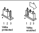
Flash PROM Update Multimedia Collection
The video content of the AnswerBook2 collection is very large. You may want to view it directly from the CD rather than installing this software package on a system already running an AnswerBook2 server. You also can view the video clips directly without using AnswerBook software or a browser.
Running the Video Clips from the CD
To run the video clips contained in this AnswerBook collection directly from the CD, perform the following steps:
-
Insert the Flash PROM Update Multimedia AnswerBook CD into your CD-ROM drive.
-
Change directory to, or bring up file manager, and go to the top level of the CD-ROM volume. This should look similar to:
% cd /cdrom/flash_answerbook
where cdrom is the mount-point for the CD-ROM device and flash_answerbook is the name of the CD-ROM volume.
-
To run the viewing script, type:
% ./watch-videos
-
Select the first video clip you want to see.
-
Before you view another video clip, dismiss the viewer that displayed the previous video clip.
Running an AnswerBook2 Server from the CD
To run the AnswerBook2 server directly from the CD, perform the following steps:
-
Insert the Flash PROM Update Multimedia AnswerBook CD into your CD-ROM drive.
-
Open a command window and become superuser using the su command and superuser password.
-
Change directory to the top level of the CD-ROM volume.
# cd /cdrom/flash_answerbook
where cdrom is the mount-point for the CD-ROM device and flash_answerbook is the name of the CD-ROM volume.
Among other things, this directory contains the executable script ab2cd.
-
# ./ab2cd
-
If you have existing AnswerBook2 documentation collections installed on your server machine and you want the CD-driven server software to recognize those collections, use the following command:
# ./ab2cd -s
This causes the CD-driver server software to scan for other collections installed on this system and add them to its database.
-
You can now access the document server using the following URL: http://server:8888/
Where server is the name of the machine to which the CD is attached.
-
To view video clips that are contained in an AnswerBook document, edit your browser's preferences to specify an MPEG Video application.
For example, to make use of the ShowMe(TM) TV(TM) software provided on this CD in a Netscape Communicator browser, perform these steps:
-
In the top bar menu of the browser, select Edit --> Preferences.
-
In the Preferences window, select the category Navigator and the subcategory Applications.
-
In the list of Applications, specify that MPEG Video is handled by the following: showmetv -nowrap %s.
-
Click OK to apply this change to the Preferences.
-
-
In the document, click the video clip icon to launch the viewer.
-
Before you view another video clip, dismiss the viewer that displayed the previous video clip.
-
To stop running the AnswerBook server from the CD, run the following command:
# /cdrom/flash_answerbook/ab2cd stop
Notes on Running AnswerBook2 from a CD
The following paragraphs provide important information about running the AnswerBook2 server from the CD.
Default AnswerBook2 Port
The AnswerBook2 server run from the CD always runs on port 8888. If you already have an AnswerBook2 server running on your system using the default port (8888), the ab2cd script will display the following message:
A document server is already running on this system as server:8888.
Shut down the current server before running the ab2cd command. Use the following command to shut down the existing server:
# /usr/lib/ab2/bin/ab2admin -o stop
Stopping the AnswerBook2 Server Process
Always use ab2cd stop to stop the server running from the CD. Do not use /etc/init.d/ab2mgr stop to stop the CD-based server.
The ab2cd stop command stops the AnswerBook2 server process and cleans up all files in the /tmp/.ab2/ and /tmp/ab2cd_config/ directories. The /etc/init.d/ab2mgr stop command stops all server processes, but does not clean up the files in the /tmp/.ab2/ and /tmp/ab2cd_config/ directories.
Running Two AnswerBooks
To run two AnswerBook2 servers (one on your system, one from the CD), keep these rules in mind:
Startup
-
The /etc/init.d/ab2mgr start command always starts the server on your system.
-
The ab2cd command always starts the server from the CD.
Shutdown
-
Always use the ab2cd stop command to stop the server running from the CD.
-
To stop both servers, first use the ab2cd stop command to stop the server running from the CD, then use either /etc/init.d/ab2mgr stop or /usr/lib/ab2/bin/ab2admin -o stop to stop the server running on your system.
- © 2010, Oracle Corporation and/or its affiliates
