Chapter 3 Cabling Diagrams
This chapter contains illustrations to supplement the procedures in this book that involve cabling your storage array.
Sun StorEdge 3120 Cabling Diagrams
Installing a Sun StorEdge 3120 Storage Array
For the procedure about how to install and cable the storage arrays, see the Sun StorEdge 3120 SCSI Array Quick Installation Guide. For a URL to this storage documentation, see Related Documentation.
Note –
In the configuration that is outlined in Figure 3–1, you must mirror the Sun StorEdge 3120 storage array against another storage array. This storage array need not be a Sun StorEdge 3120 storage array.
Figure 3–1 Cabling a Single-Bus, Multi-Initiator Sun StorEdge 3120 Storage Array
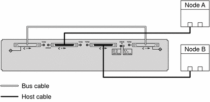
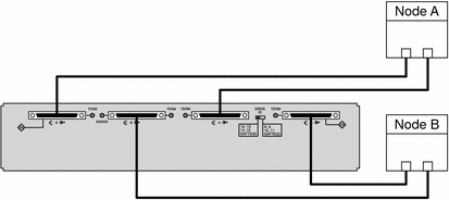
Figure 3–2 Cabling a Dual-Bus, Multi-Initiator Sun StorEdge 3120 Storage Array
Sun StorEdge 3310 and 3320 SCSI Cabling Diagrams
Installing a Sun StorEdge 3310 or 3320 Storage Array
Ensure that the cable does not exceed bus-length limitations. For more information about bus-length limitations, see the documentation that shipped with your hardware.
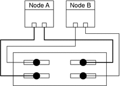
For the procedure about how to cable the storage arrays, see the Sun StorEdge 3000 Family Installation, Operation, and Service Manual. For a URL to this storage documentation, see Related Documentation.
Figure 3–3 Cabling a Dual-Bus, Multi-Initiator Sun StorEdge 3310 or 3320 Storage Array
Adding a Sun StorEdge 3310 or 3320 Storage Array
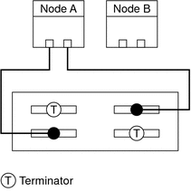
If the storage array is in dual-bus, multi-initiator mode, see Figure 3–4 for a diagram about how to cable and terminate the storage arrays.
Do not power on the storage array until the storage array is cabled to the first node.
Ensure that the cable does not exceed bus-length limitations. For more information about bus-length limitations, see the documentation that shipped with your hardware.
For the procedure about how to cable the storage arrays, see the Sun StorEdge 3000 Family Installation, Operation, and Service Manual. For a URL to this storage documentation, see Related Documentation.
Figure 3–4 Cabling a Dual-Bus, Multi-Initiator Sun StorEdge 3310 or 3320 Storage Array: Part 1
If the storage array is in dual-bus, multi-initiator mode, remove the terminators and connect the storage array to the second node. See Figure 3–5 for a diagram about how to cable the storage array to both nodes.
For the procedure about how to cable the storage arrays, see the Sun StorEdge 3000 Family Installation, Operation, and Service Manual. For a URL to this storage documentation, see Related Documentation.
Ensure that the cable does not exceed bus-length limitations. For more information about bus-length limitations, see the documentation that shipped with your hardware.
Figure 3–5 Cabling a Dual-Bus, Multi-Initiator Sun StorEdge 3310 or 3320 Storage Array: Part 2

SPARC: Sun StorEdge D1000 Cabling Diagrams
SPARC: Installing a Sun StorEdge D1000 Storage Array
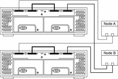
Connect the cables to the storage arrays, as shown in Figure 3–6.
Ensure that the entire bus length that is connected to each storage array is less than 25 m. This measurement includes the cables to both nodes, as well as the bus length that is internal to each storage array, node, and the host adapter.
Figure 3–6 SPARC: Installing a Sun StorEdge D1000 Mirrored-Pair Configuration: An Example
SPARC: Adding a Sun StorEdge D1000 Storage Array
Ensure that the entire SCSI bus length to each enclosure is less than 25 m. This measurement includes the cables to both nodes, as well as the bus length that is internal to each enclosure, node, and host adapter. Refer to the documentation that shipped with the enclosure for other restrictions about SCSI operation.
Figure 3–7 SPARC: Adding a Sun StorEdge D1000 Mirrored-Pair Configuration: Part 1
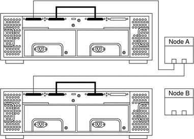
Connect the storage array to the host adapters by using differential SCSI cables as shown in see Figure 3–8.
Figure 3–8 SPARC: Adding a Sun StorEdge D1000 Mirrored-Pair Configuration: Part 2

SPARC: Replacing a Sun StorEdge D1000 Storage Array
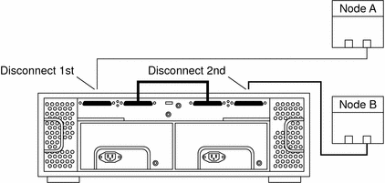
Disconnect the SCSI cables from the storage array. Remove the SCSI cables in the order that is shown in Figure 3–9.
Figure 3–9 SPARC: Disconnecting the SCSI Cables From a Sun StorEdge D1000 Storage Array
SPARC: Removing a Sun StorEdge D1000 Storage Array
Disconnect the SCSI cables from the storage array. Remove the SCSI cables in the order that is shown in Figure 3–10.
Figure 3–10 SPARC: Disconnecting the SCSI Cables From a Sun StorEdge D1000 Storage Array

SPARC: Sun StorEdge Multipack Cabling Diagrams
SPARC: Installing a Sun StorEdge Multipack Storage Array
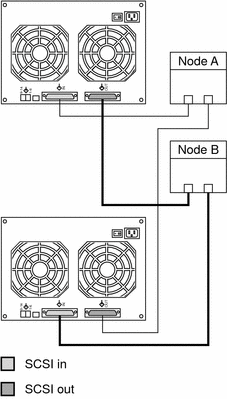
Connect the cables to the storage array, as shown in Figure 3–11.
Ensure that the entire SCSI bus length to each storage array conforms to the distances in Table 1–1. This measurement includes the cables to both nodes, as well as the bus length that is internal to each storage array, node, and host adapter. Refer to the documentation that shipped with the storage array for other restrictions about SCSI operation.
Figure 3–11 SPARC: Installing a Sun StorEdge Multipack Mirrored-Pair Configuration: An Example
SPARC: Adding a Sun StorEdge Multipack Storage Array
Connect the single-ended SCSI cable between the node and the storage arrays, as shown in Figure 3–12.
Ensure that the entire SCSI bus length to each storage array conforms to the distances in Table 1–1. This measurement includes the cables to both nodes, as well as the bus length that is internal to each storage array, node, and host adapter. Refer to the documentation that shipped with the storage array for other restrictions about SCSI operation.
Figure 3–12 SPARC: Adding a Sun StorEdge Multipack Mirrored-Pair Configuration: Part 1
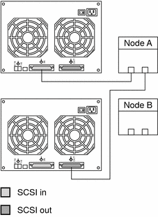
Connect the storage arrays to the host adapters by using single-ended SCSI cables, as shown in Figure 3–13.
Figure 3–13 SPARC: Adding a Sun StorEdge Multipack Mirrored-Pair Configuration: Part 2

SPARC: Replacing a Sun StorEdge Multipack Storage Array
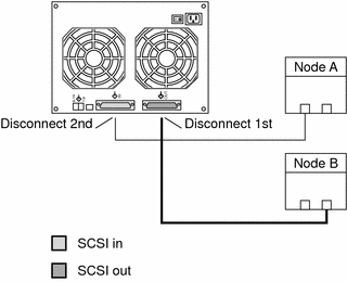
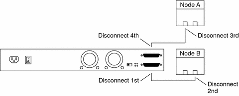
Disconnect the SCSI cables from the storage array. Disconnect the SCSI cable on the SCSI OUT connector, and then disconnect the cable on the SCSI IN connector, as shown in Figure 3–14.
Figure 3–14 SPARC: Replacing a Sun StorEdge Multipack Storage Array
SPARC: Removing a Sun StorEdge Multipack Storage Array
Disconnect the SCSI cables from the storage array. Disconnect the SCSI cables in the order that is shown in Figure 3–15.
Figure 3–15 SPARC: Removing a Sun StorEdge Multipack Storage Array

SPARC: Sun StorEdge Netra D130/S1 Cabling Diagrams
SPARC: Installing a Sun StorEdge Netra D130/S1 Storage Array
If your host has only one SCSI port, see SPARC: Single-SCSI-Port Hosts. If your host has two SCSI ports, see SPARC: Dual-SCSI-Port Hosts.
SPARC: Single-SCSI-Port Hosts
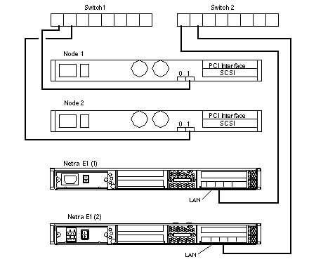
When you install the storage array on single-SCSI-port hosts use the Netra E1 PCI Expander for the second host SCSI port. Figure 3–16 shows an overview of the installation. The storage arrays are cabled so that no single point of failure is in the cluster. Netra E1 PCI Expanders provide the second SCSI port for the 1RU form-factor hosts such as the Netra t1, x1, or t1 200.
Figure 3–16 SPARC: Sun StorEdge Netra D130/S1 Mirrored-Pair Configuration With Single SCSI Port Hosts: An Example
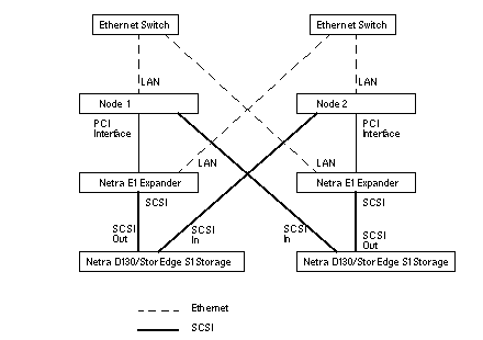
To cable the storage arrays correctly, adhere to the bus-length restrictions that are listed in the documentation that shipped with your host adapter. In a Sun Cluster environment, this cable-length measurement includes the cables to both nodes. This cable-length measurement also includes the bus length that is internal to each storage array, node, and host adapter.
Figure 3–17 SPARC: Cabling a Sun StorEdge Netra D130/S1 Mirrored-Pair Configuration With Single-SCSI-Port Hosts
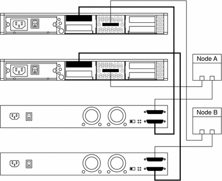
Figure 3–18 SPARC: Cabling a Sun StorEdge Netra D130/S1 Mirrored-Pair Configuration With Single-SCSI-Port Hosts and Netra E1 PCI Expanders
SPARC: Dual-SCSI-Port Hosts
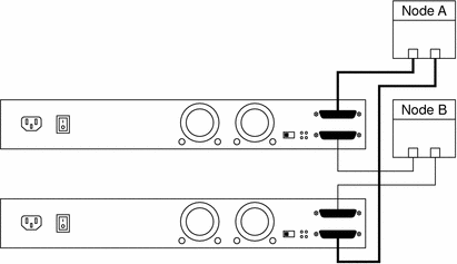
To cable the storage arrays correctly, adhere to the bus-length restrictions that are listed in the documentation that shipped with your host adapter. In a Sun Cluster environment, this cable-length measurement includes the cables to both nodes. This cable-length measurement also includes the bus length that is internal to each storage array, node, and host adapter.
Figure 3–19 SPARC: Cabling a Sun StorEdge Netra D130/S1 Mirrored-Pair Configuration With Dual-SCSI-Port Hosts
SPARC: Adding a Sun StorEdge Netra D130/S1 Storage Array
To cable the storage arrays correctly, adhere to the bus-length restrictions that are listed in the documentation that shipped with your host adapter. In a Sun Cluster environment, this cable-length measurement includes the cables to both nodes. This cable-length measurement also includes the bus length that is internal to each storage array, node, and host adapter.
Figure 3–20 SPARC: Adding a Sun StorEdge Netra D130/S1 Storage Array Mirrored-Pair Configuration: Part 1
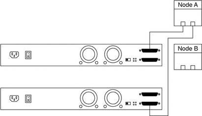
Figure 3–21 SPARC: Adding a Sun StorEdge Netra D130/S1 Mirrored-Pair Configuration: Part 2

SPARC: Replacing a Sun StorEdge Netra D130/S1 Storage Array
Disconnect the SCSI cables from the storage arrays. Disconnect the cable on the SCSI OUT connector, and then disconnect the cable on the SCSI IN connector, as shown in Figure 3–22.
Figure 3–22 SPARC: Replacing a Sun StorEdge Netra D130/S1 Storage Array
SPARC: Removing a Sun StorEdge Netra D130/S1 Storage Array
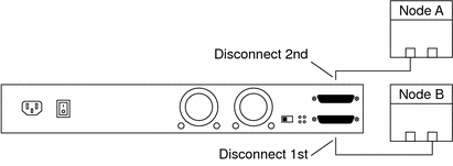
Disconnect the SCSI cables from the storage arrays. Disconnect the SCSI cable in the order that is shown in Figure 3–23.
Figure 3–23 SPARC: Removing a Sun StorEdge Netra D130/S1 Storage Array
SPARC: Sun StorEdge D2 Cabling Diagrams
SPARC: Installing a Sun StorEdge D2 Storage Array
You can install a single storage array by using a split-bus configuration. You can install two storage arrays by using a single-bus configuration.
Figure 3–24 SPARC: Installing a Sun StorEdge D2 Split-Bus Configuration: An Example
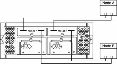
To use a single storage array in a Sun Cluster environment, you must use the split-bus configuration.
As Figure 3–24 shows, the split-bus configuration requires that the storage array contain two Environmental Service Modules (ESM). Each ESM is connected to two nodes. Each ESM controls half the disks in the storage array and the data is mirrored by using a volume manager.
Figure 3–25 SPARC: Installing a Sun StorEdge D2 Single-Bus Configuration: An Example
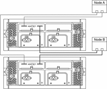
As Figure 3–25 shows, the single-bus configuration requires two storage arrays that each contain a single Environmental Service Module (ESM). The ESM controls all disks on the storage array in which it is installed and the volume manager implements mirroring between the two storage arrays. Each ESM must be connected to two nodes.
SPARC: Adding a Sun StorEdge D2 Storage Array
Ensure that the entire bus length that is connected to the storage array is less than 12 m. The bus length includes the cables from the ESM to the host adapter. See the documentation that shipped with your hardware for internal bus length.
-
For split-bus configurations, see Figure 3–26 and Figure 3–28.
-
For single-bus configurations, see Figure 3–27 and Figure 3–29.
Figure 3–26 SPARC: Adding a Sun StorEdge D2 Split-Bus Configuration: Part 1
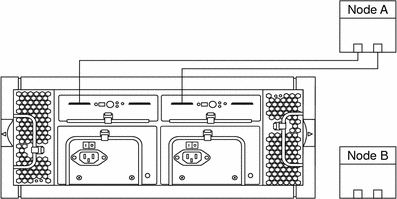
Figure 3–27 SPARC: Adding a Sun StorEdge D2 Single-Bus Configuration: Part 1
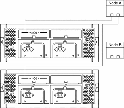
Figure 3–28 SPARC: Adding a Sun StorEdge D2 Split-Bus Configuration: Part 2

Figure 3–29 SPARC: Adding a Sun StorEdge D2 Single-Bus Configuration: Part 2

- © 2010, Oracle Corporation and/or its affiliates
