| Exit Print View | |
Sun Datacenter InfiniBand Switch 72 Topic Set |

|
Documentation, Support, and Training
Understanding Switch Specifications
Network Management Connector and Pins
USB Management Connector and Pins
Understanding InfiniBand Cabling
Floor and Underfloor Delivery of InfiniBand Cables
Overhead Delivery of InfiniBand Cables
Understanding the Installation
Install the Switch in the Rack
Accessing the Management Controller
Access the Management Controller From the Network Management Port
Access the Management Controller From the USB Management Port
Verifying the InfiniBand Fabric
Discover the InfiniBand Fabric Topology
Perform Diagnostics on the InfiniBand Fabric
 | Caution - InfiniBand cables must never turn tighter than a 5-inch (127 mm) radius. A tighter radius damages the wires and fibers inside the cable. |
Note - When you install the InfiniBand cables, connect cables to the lower connectors first, then connect cables to the upper connectors.
Identify the prerequisite and subsequent installation tasks that you must perform in conjunction with this procedure.
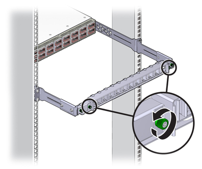
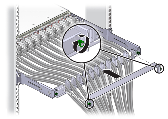
Loosen the two captive thumbscrews that secure the cover to the cable management bracket.
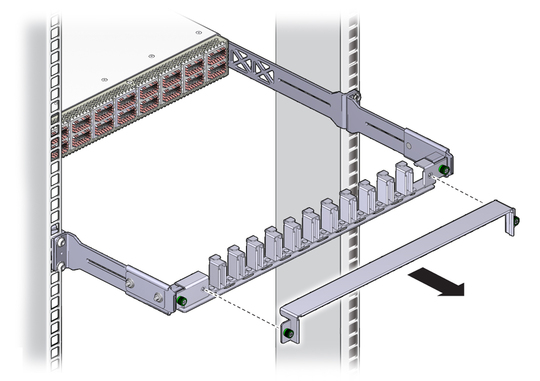
Lift the cover off.
Remove the protective cap from the connector and visually inspect the cable connector.
The shell should not be bent and should be parallel to the inner boards. If the connector is bent or damaged, use a different cable.
Ensure that the retraction strap is forward.
Orient the cable connector to the CXP receptacle squarely and horizontally.
Ensure that the upper shell just touches the underside of the top of the receptacle on the rear panel.
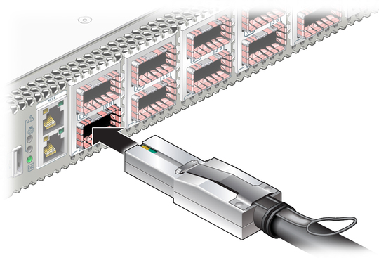
Slowly move the connector in.
As you slide the connector in, the top of the shell should scrape against the underside of the top of the CXP receptacle.
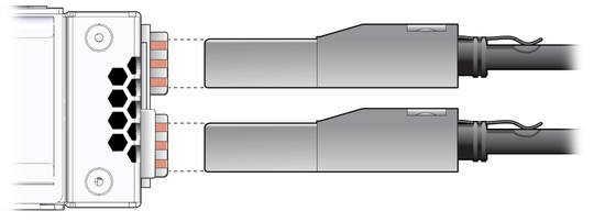
Continue to push the connector in until the hooks catch onto the top of the receptacle.
Place the cable into the open slot on the cable management bracket.
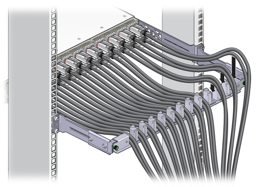
Repeat ![]() Step 4 through
Step 4 through ![]() Step 9 for all cables to be installed.
Step 9 for all cables to be installed.
Replace the cover for the cable management bracket and tighten the thumbscrews.
Route the InfiniBand cables so that they do not interfere with other cables, or with servicing the Sun Datacenter InfiniBand Switch 72 or other systems.
Use hook and loop fastener straps to bundle and secure the cables.
Note - Do not use cable zip ties to bundle or secure the cable, because the ties damage the wires inside the cable.
Check that the Link LEDs for cabled links are lit green.
If the Link LED is unlit, the link is down. If the
Link LED flashes, there are symbol errors. See ![]() Check Link Status LEDs.
Check Link Status LEDs.
If installed, close the rack doors to maintain EMI compliance.
Check the link status.
See ![]() Check Link Status.
Check Link Status.