| C H A P T E R 5 |
|
LED Module FRUs |
This chapter provides instructions for replacing the LED and reset switch module. For convenience, this module will be called the LED module.
Topics covered in this chapter are:
The following parts are included in the LED module replacement kit:
The following tools are required to complete this procedure:
1. Power off both RAID controllers.
2. If attached, unlock the front bezel cover with the provided key.
3. Grasp the front bezel cover on both sides and pull it forward and then down.
4. Press the right bezel arm (hinge) toward the left side to release it from the chassis hole.
The left bezel arm also disengages.
5. Note the location of the chassis bezel holes on each ear.
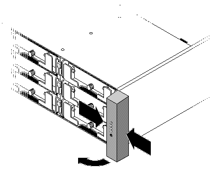
6. Remove the plastic cap from the right ear of the array.
a. Squeeze both sides of the cap at the top and the bottom.
b. Turn the cap toward the center of the array until it disengages and pull it free.
Be sure to follow Section 1.2, Static Electricity Precautions
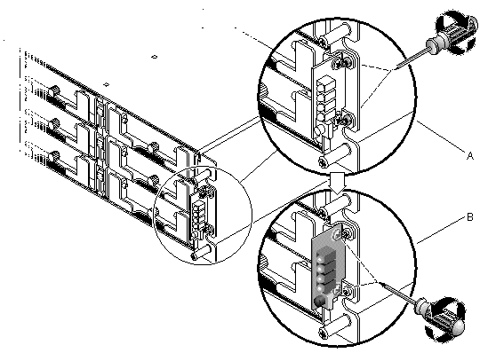
1. Remove the two panhead screws (B in FIGURE 5-2) holding the LED module to the bracket.
|
Note - If the bracket screws (A in FIGURE 5-2) obstruct the LED module screws (B in FIGURE 5-2), the chassis will have to be removed from the rack (if it is a rackmounted array) or the case (if it is a tabletop array) to gain access to the bracket screws and remove them. Two #4-40 x 1/4-inch flathead screws are provided to replace the bracket screws, should they become damaged when removed. For details on removing the cover from a tabletop array, see Section 2.4, Adding or Removing the Tabletop Cover. |
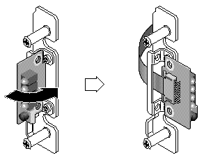
2. Carefully detach the LED module from the ribbon cable by pulling out the tiny cable lock drawer and sliding the LED module free.
Be sure to follow Section 1.2, Static Electricity Precautions.
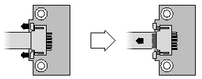
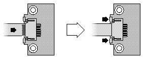
1. Pull out the cable lock drawer on the new LED module.
2. Place the new LED module against the bracket and carefully slide the ribbon cable into the cable lock drawer.
3. Close the cable lock drawer to reconnect the cable to the LED module.
|
Note - The blue side of the ribbon cable must face towards the LED module and the ribbon contact area must be completely inserted into the LED module before the lock drawer is closed. |
4. Insert the panhead screws through the LED module and attach the LED module to the chassis.
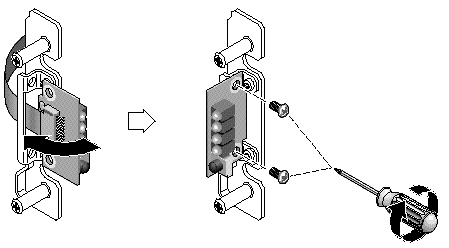
5. If the flathead screws (A in FIGURE 5-2) were removed, reattach these screws through the chassis flange into the bracket.
Replacement screws are provided in the ship kit in case the original screws were damaged during removal.
6. If it was removed in Step 1 in Section 5.1.3, restore the chassis to its case or rack.
1. Push the top and bottom of the ear cap onto the ear, pressing in on the top side toward the center of the array until the ear cap snaps into place.
2. Insert the bezel arms into the chassis holes.
3. Lift the bezel into position and press it onto the front of the chassis until it is flush with the front.
4. Lock the bezel in the closed position with the keys.
5. Remove the keys if they were not initially inserted into the chassis.
6. Power on both power supply modules.
The following parts are included in the LED module replacement kit:
The following tools are required to complete this procedure:
1. Power off both RAID controllers.
2. If attached, unlock the front bezel cover with the provided key.
3. Grasp the front bezel cover on both sides and pull it forward and then down.
4. Press the right bezel arm (hinge) toward the left side to release it from the chassis hole.
The left bezel arm also disengages.
5. Note the location of the chassis bezel holes on each ear.
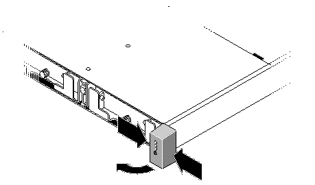
6. Remove the plastic cap from the right ear of the array.
a. Squeeze both sides of the cap at the top and the bottom.
b. Turn the cap toward the center of the array until it disengages and pull it free.
Be sure to follow Section 1.2, Static Electricity Precautions.
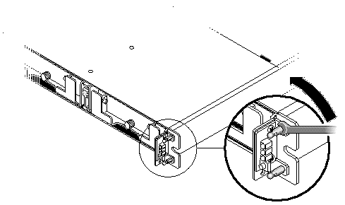
1. Remove the ball studs holding the LED module to the chassis.
|
Note - If you cannot access the ball studs to remove them, the chassis will have to be removed from the rack. |
2. Unfold the ribbon cable and detach it from the LED module by pulling out the tiny cable lock drawer and sliding the LED module free.
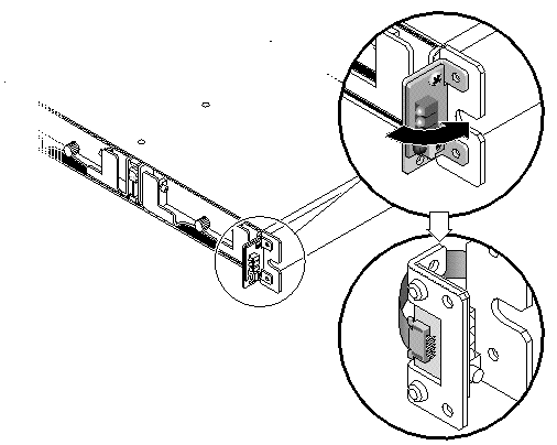
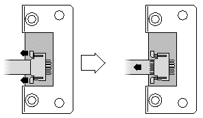
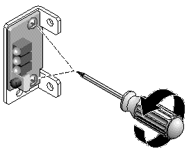
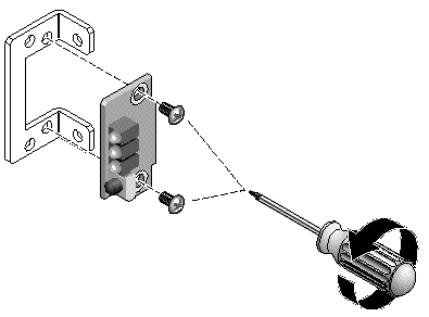
3. Remove the two panhead screws holding the LED module to the bracket.
1. Attach the new LED module to the bracket using the two screws from Step 3 in Section 5.2.3.
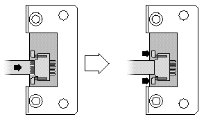
2. Pull out the cable lock drawer on the new LED module.
3. Insert the ribbon cable into the new LED module and close the cable lock drawer to reconnect the cable to the LED module.
|
Note - The blue side of the ribbon cable must face towards the LED module and the ribbon contact area must be completely inserted into the LED module before the lock drawer is closed. |
4. Fold the ribbon to lay flat against the back of the LED module and attach the LED module to the chassis with the ball studs from Step 1 in Section 5.2.3, Removing the LED Module.
5. If the ball studs were attached to flathead screws, reattach these screws through the bracket to the ball studs.
Replacement screws are provided in the ship kit in case the original screws were damaged during removal.
6. If it was removed in Step 1 in Section 5.2.3, restore the chassis to its rack.
1. Push the top and bottom of the ear cap onto the ear, pressing in on the top side toward the center of the array until the ear cap snaps into place.
2. Insert the bezel arms into the chassis holes.
3. Lift the bezel into position and press it onto the front of the chassis until it is flush with the front.
4. Lock the bezel in the closed position with the keys.
5. Remove the keys if they were not initially inserted into the chassis.
6. Power on both power supply modules.
Copyright © 2007, Dot Hill Systems Corporation. All rights reserved.