| C H A P T E R 3 |
|
Configuration Defaults and Guidelines |
This chapter lists default configurations and provides guidelines you need to be aware of when configuring your array.
This chapter covers the following topics:
This section provides default configuration information for drives and channel settings.
Sun StorEdge 3000 family arrays are preconfigured with a single RAID 0 logical drive mapped to LUN 0, and no spare drives. This is not a usable configuration. You must delete this logical drive and create new logical drives, as shown in First-Time Configuration for SCSI Arrays and First-Time Configuration for FC or SATA Arrays.
Sun StorEdge 3000 family arrays are preconfigured with the channel settings shown in the following tables. The most common reason to change a host channel to a drive channel is to attach expansion units to a RAID array.
Sun StorEdge 3310 SCSI array default channel settings are shown in TABLE 3-1.
Sun StorEdge 3510 FC array default channel settings are shown in TABLE 3-2.
Sun StorEdge 3511 SATA array default channel settings are shown in TABLE 3-3.
TABLE 3-4 lists the maximum number of physical and logical drives, partitions per logical drive and logical volume, and maximum number of logical unit number (LUN) assignments for each array.
|
Sun StorEdge 3310 SCSI array and Sun StorEdge 3320 SCSI array |
|||||
|
Sun StorEdge 3510 FC array with Sun StorEdge 3511 SATA expansion units[1] |
The following tables show the maximum number of disks per logical drive, and the maximum usable capacity of a logical drive, depending on RAID level and optimization mode.
The maximum capacity per logical drive supported by the RAID firmware is:
Actual logical drive maximum capacities are usually determined by practical considerations or the amount of disk space available.
TABLE 3-5 shows the usable capacity of the drives available in Sun StorEdge 3000 family arrays.
|
Note - The 250 Mbyte of reserved space on each drive used for storing controller metadata is not included in this table, since it is not available for storing data. |
TABLE 3-6 shows the maximum usable storage capacity for Sun StorEdge 3310 SCSI arrays, Sun StorEdge 3320 SCSI arrays, Sun StorEdge 3510 FC arrays, and Sun StorEdge 3511 SATA arrays, using the maximum number of expansion units, fully populated with the largest currently available drives.
|
Sun StorEdge 3310 SCSI array and Sun StorEdge 3320 SCSI array |
|||||
TABLE 3-7 shows the maximum number of disks that can be used in a single logical drive, based upon the drive size, and the optimization method chosen.
|
Note - Except for SATA arrays using random optimization, it is possible (though impractical) to employ all available disks in a single logical drive |
TABLE 3-8 shows the maximum usable capacity of a single logical drive in a Sun StorEdge 3510 FC array, depending on drive size.
TABLE 3-9 shows the maximum usable capacity of a single logical drive in a Sun StorEdge 3310 SCSI array, depending on drive size.
TABLE 3-10 shows the maximum usable capacity of a single logical drive in a Sun StorEdge 3511 SATA array, depending on drive size.
This section provides guidelines for dual-controller and single-controller operation.
Keep the following operation details in mind when configuring a dual-controller array.
The two controllers continuously monitor each other. When either controller detects that the other controller is not responding, the working controller immediately takes over and disables the failed controller.
An active-to-standby configuration is also available but is not usually selected. In this configuration, assigning all the logical drives to one controller means that the other controller remains idle, becoming active only if the primary controller fails.
Keep the following operation details in mind when configuring a single-controller array.
A secondary controller is used only in dual-controller configurations for redistributed I/O and for failover.
Using two single controllers in a clustering environment with host-based mirroring provides some of the advantages of using a dual controller. However you still need to disable the Write-Back Cache in case one of the single controllers fails, to avoid the risk of data corruption. For this reason, a dual controller configuration is preferable.
Before creating or modifying logical drives, determine the appropriate optimization mode for the RAID array. The controller supports two optimization modes, sequential I/O and random I/O. Sequential I/O is the default mode.
When you specify sequential or random cache optimization, the controller determines a default stripe size for newly-created logical drives. But you can specify whatever stripe size you choose for each logical drive when you create it, enabling you to maximize performance by matching stripe size with your application requirements. Since different applications may use different logical drives, this functionality provides you with greatly increased flexibility.
See Cache Optimization Mode (SCSI) for information about how to set the cache optimization mode on a Sun StorEdge 3310 SCSI array or Sun StorEdge 3320 SCSI array. See Cache Optimization Mode (FC and SATA) for information about how to set the cache optimization mode for a Sun StorEdge 3510 FC array or Sun StorEdge 3511 SATA array.
The RAID array's cache optimization mode determines the cache block size used by the controller for all logical drives. An appropriate cache block size improves performance when a particular application uses either large or small stripe sizes:
Once logical drives are created, you cannot use the RAID firmware's Optimization for Random I/O or Optimization for Sequential I/O menu option to change the optimization mode without deleting all logical drives. You can, however, use the Sun StorEdge CLI set cache-parameters command to change the optimization mode while logical drives exist. Refer to the Sun StorEdge 3000 Family CLI 2.0 User's Guide for more information.
Since the cache block size works in conjunction with stripe size, the optimization mode you choose determines default logical drive stripe sizes that are consistent with the cache block size setting. But you can now fine-tune performance by specifying each logical drive's stripe size so that it matches your application needs, using a firmware menu option that is available at the time you create the logical drive. See Cache Optimization Mode and Stripe Size Guidelines for more information.
See (Optional) Configure the logical drive stripe size. for information about how to set the stripe size for a logical drive you are creating on a Sun StorEdge 3310 SCSI array or Sun StorEdge 3320 SCSI array. See (Optional) Configure the logical drive stripe size. for information about how to set the stripe size for a logical drive you are creating on a Sun StorEdge 3510 FC array or Sun StorEdge 3511 SATA array.
The cache write policy determines when cached data is written to the disk drives. The ability to hold data in cache while it is being written to disk can increase storage device speed during sequential reads. Write policy options include write-through and write-back.
When write-through cache is specified, the controller writes the data to the disk drive before signaling the host operating system that the process is complete. Write-through cache has slower write operation and throughput performance than write-back cache, but it is safer, with minimum risk of data loss on power failure. Because a battery module is installed, power is supplied to the data cached in memory and the data can be written to disk after power is restored.
When write-back cache is specified, the controller receives the data to write to disk, stores it in the memory buffer, and immediately sends the host operating system a signal that the write operation is complete, before the data is actually written to the disk drive. Write-back caching improves the performance of write operations and the throughput of the controller card.
Write-back cache is enabled by default. When you disable write-back cache, write-through cache is automatically enabled. The setting you specify becomes the default global cache setting for all logical drives. With RAID firmware version 4.11 and later, the cache setting can now be individually tailored for each logical drive. When you configure a logical drive, you can set its individual cache write policy to default, write-back, or write-through.
If you specify default for an individual logical drive, the global write policy is assigned to it. Then, if the global cache write policy that applies to the entire RAID array is changed, any logical drive that has been assigned the default setting write policy is also changed.
If you specify write-back or write-through for an individual logical drive, the cache write policy for that drive remains the same regardless of any changes to the global cache write policy.
If you have specified a global write-back policy, you can also configure the RAID array to automatically change from a write-back cache policy to a write-through cache policy when one or more of the following trigger events occur:
Once the condition that led to the trigger event is rectified, the cache policy automatically returns to its previous setting. For more information on configuring the write policy to automatically switch from write-back cache to write-through cache, see Event Trigger Operations.
Sun StorEdge 3510 FC arrays and Sun StorEdge 3511 SATA arrays support the following connection protocols:
This protocol can be used only with a switched fabric network configuration, also called a storage area network (SAN). The point-to-point protocol supports full duplex communication, but only allows one ID per channel.
The loop mode can be used with direct-attached storage (DAS) or SAN configurations. Loop mode supports only half-duplex communication, but allows up to eight IDs per channel.
The following guidelines apply when implementing point-to-point configurations and connecting to fabric switches.
The controller displays a warning if the user is in point-to-point mode and tries to add an ID to the same channel but on the other controller. The warning is displayed because you have the ability to disable the internal connection between the channels on the primary and secondary controller using the set inter-controller link CLI command and, by doing this, you can have one ID on the primary and another ID on the secondary as a legal operation.
However, if you ignore this warning and add an ID to the other controller, the RAID controller does not allow a login as an FC-AL port because this would be illegal in a point-to-point configuration.
To use more than 64 LUNs, you must change to Loop only mode, add host IDs to one or more channels, and add 32 LUNs for each host ID.
|
Note - In public loop mode, the array can have a maximum of 1024 LUNs, where 512 LUNs are dual-mapped across two channels, primary and secondary controller, respectively. |
A point-to-point configuration has the following characteristics:
In a dual-controller array, one controller automatically takes over all operation of a second failed controller in all circumstances. However, when an I/O controller module needs to be replaced and a cable to an I/O port is removed, that I/O path is broken unless multipathing software has established a separate path from the host to the operational controller. Supporting hot-swap servicing of a failed controller requires the use of multipathing software, such as Sun StorEdge Traffic Manager software, on the connected servers.
Remember these important considerations:
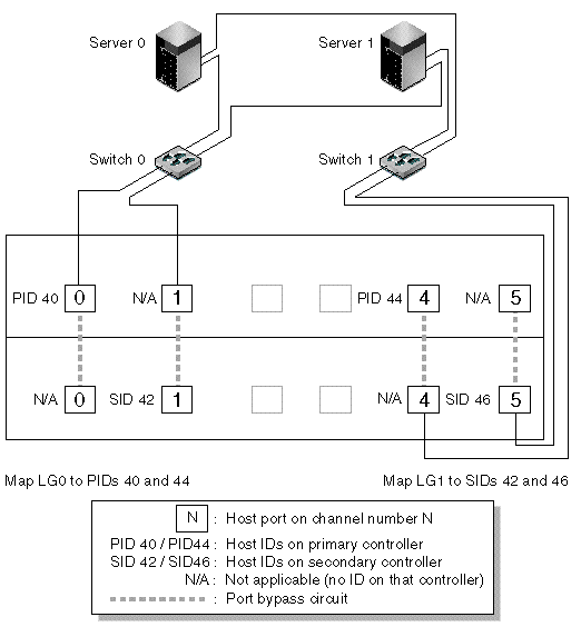
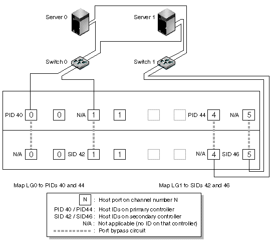
The following figures show the channel numbers (0, 1, 4, and 5) of each host port and the host ID for each channel. N/A means that the port does not have a second ID assignment. The primary controller is the top I/O controller module, and the secondary controller is the bottom I/O controller module.
The dashed lines between two ports indicate a port bypass circuit that functions as a mini-hub and has the following advantages:
In FIGURE 3-1 and FIGURE 3-2, with multipathing software to reroute the data paths, each logical drive remains fully operational when the following conditions occur:


TABLE 3-11 summarizes the primary and secondary host IDs assigned to logical drives 0 and 1, based on FIGURE 3-1 and FIGURE 3-2.
|
Perform the following steps, which are described in more detail later in this guide, to set up a typical point-to-point SAN configuration based on FIGURE 5-1 and FIGURE 5-2.
1. Check the position of installed small form-factor pluggable transceivers (SFPs). Move them as necessary to support the connections needed.
You need to add SFP connectors to support more than four connections between servers and a Sun StorEdge 3510 FC array or Sun StorEdge 3511 SATA array. For example, add two SFP connectors to support six connections and add four SFP connectors to support eight connections.
2. Connect expansion units, if needed.
3. Create at least two logical drives (logical drive 0 and logical drive 1) and configure spare drives.
Leave half of the logical drives assigned to the primary controller (default assignment). Assign the other half of the logical drives to the secondary controller to load-balance the I/O.
4. Create up to 32 partitions (LUNs) in each logical drive.
5. Change the Fibre Connection Option to "Point to point only" ("view and edit Configuration parameters  Host-side SCSI Parameters
  Fibre Connections Option").
6. For ease of use in configuring LUNs, change the host IDs on the four channels to the following assignments:
Channel 0: PID 40 (assigned to the primary controller)
Channel 1: PID 41 (assigned to the primary controller)
Channel 4: SID 50 (assigned to the secondary controller)
Channel 5: SID 51 (assigned to the secondary controller)
|
Note - Do not use the "Loop preferred, otherwise point to point" menu option. This command is reserved for special use and should be used only if directed by technical support. |
7. Map logical drive 0 to channels 0 and 1 of the primary controller.
Map LUN numbers 0 through 31 to the single ID on each host channel.
8. Map logical drive 1 to channels 4 and 5 of the secondary controller.
Map LUN numbers 0 through 31 to the single ID on each host channel. Since each set of LUNs is assigned to two channels for redundancy, the total working maximum number of LUNs is 64 LUNs.
|
Note - The LUN ID numbers and the number of LUNs available per logical drive can vary according to the number of logical drives and the ID assignments you want on each channel. |
9. Connect the first switch to ports 0 and 4 of the upper controller.
10. Connect the second switch to ports 1 and 5 of the lower controller.
11. Connect each server to each switch.
12. Install and enable multipathing software on each connected server.
The multipathing software prevents path failure but does not alter the controller redundancy through which one controller automatically takes over all functions of a second failed controller.
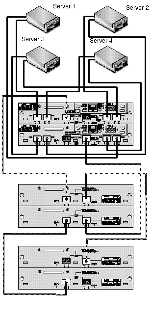
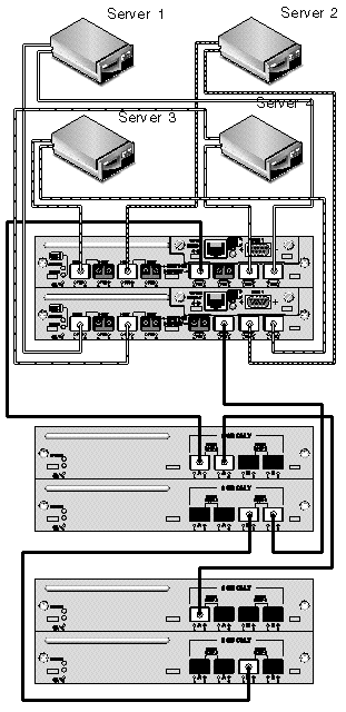
The typical direct attached storage (DAS) configuration shown in FIGURE 3-3 and FIGURE 3-4 includes four servers, a dual-controller array, and two expansion units. Expansion units are optional.
Servers, as shown in FIGURE 3-3 and FIGURE 3-4, are connected to the channels shown in TABLE 3-12.
Establishing complete redundancy and maintaining high availability requires the use of multipathing software such as Sun StorEdge Traffic Manager software. To configure for multipathing:
1. Establish two connections between each server and the array.
2. Install and enable multipathing software on the server.
3. Map the logical drive each server is using to the controller channels that the server is connected to.
DAS configurations are typically implemented using a fabric loop (FL_port) mode. A loop configuration example is described under A Sample DAS Loop Configuration.
Fabric loop (FL_port) connections between a Sun StorEdge 3510 FC array or Sun StorEdge 3511 SATA array and multiple servers allow up to 1024 LUNs to be presented to servers. For guidelines on how to create 1024 LUNs, see Planning for 1024 LUNs on an FC or SATA Array (Optional, Loop Mode Only).


|
Perform the following steps, which are described in more detail later in this manual, to set up a DAS loop configuration based on FIGURE 3-3 and FIGURE 3-4.
1. Check the location of installed SFPs. Move them as necessary to support the connections needed.
You need to add SFP connectors to support more than four connections between servers and a Sun StorEdge 3510 FC array or Sun StorEdge 3511 SATA array. For example, add two SFP connectors to support six connections and add four SFP connectors to support eight connections.
2. Connect expansion units, if needed.
3. Create at least one logical drive per server, and configure spare drives as needed.
4. Create one or more logical drive partitions for each server.
5. Confirm that the Fibre Connection Option is set to Loop only.
|
Note - Do not use the "Loop preferred, otherwise point to point" menu option. This command is reserved for special use and should be used only if directed by technical support. |
6. Set up to eight IDs on each channel, if needed (see TABLE 3-13).
7. Map logical drive 0 to channels 0 and 5 of the primary controller.
8. Map logical drive 1 to channels 1 and 4 of the secondary controller.
9. Map logical drive 2 to channels 0 and 5 of the primary controller.
10. Map logical drive 3 to channels 1 and 4 of the secondary controller.
11. Connect the first server to port FC 0 of the upper controller and port FC5 of the lower controller.
12. Connect the second server to port FC 4 of the upper controller and port FC1 of the lower controller.
13. Connect the third server to port FC 5 of the upper controller and port FC0 of the lower controller.
14. Connect the fourth server to port FC 1 of the upper controller and port FC4 of the lower controller.
15. Install and enable multipathing software on each connected server.
This section lists the typical sequence of steps for completing a first-time configuration of the array. For detailed steps and more information, see the referenced sections.
Typical steps for completing a first-time configuration of the array are as follows:
1. Set up the serial port connection.
2. Set an IP address for the controller.
3. Determine whether sequential or random optimization is more appropriate for your applications and configure your array accordingly.
See Cache Optimization Mode and Stripe Size Guidelines for more information. Also see Cache Optimization Mode (SCSI) for information about how to configure a SCSI array's optimization mode, or Cache Optimization Mode (FC and SATA) for information about how to configure an FC or SATA array's optimization mode.
4. Check physical drive availability.
See To Check Physical Drive Availability for a SCSI array. See Physical Drive Status for FC or SATA arrays.
5. (Optional) Configure host channels as drive channels.
See Channel Settings for a SCSI array. See Channel Settings for FC or SATA arrays.
6. For a Fibre Channel or SATA array, confirm or change the Fibre Connection Option (point-to-point or loop).
See Fibre Connection Protocol Guidelines and Fibre Connection Protocol for the procedure to configure the Fibre Connection protocol.
7. Revise or add host IDs on host channels.
See To Add or Delete a Unique Host ID for SCSI arrays. See To Add or Delete a Unique Host ID for FC or SATA arrays.
The IDs assigned to controllers take effect only after the controller is reset.
8. Delete default logical drives and create new logical drives as required.
See Deleting Logical Drives and Creating Logical Drives for SCSI arrays. See Deleting Logical Drives and Creating Logical Drives for FC or SATA arrays.
9. (Optional) In dual-controller configurations only, assign logical drives to the secondary controller to load-balance the two controllers.
See Controller Assignment for a SCSI array. See Controller Assignment for FC or SATA arrays.
10. (Optional) Partition the logical drives.
See Partitions for SCSI arrays. See Partitions for Fibre Channel and SATA arrays.
11. Map each logical drive partition to an ID on a host channel.
For more information, see Mapping a Partition to a Host LUN for SCSI arrays.
For information about different operating system procedures, refer to the Sun StorEdge 3000 Family Installation, Operation and Service Manual for your array.
12. (Optional) Create and apply host LUN filters to FC or SATA logical drives.
See Mapping a Partition to a Host LUN for Fibre Channel and SATA arrays.
The configuration is complete.
14. Save the configuration to a disk.
See Saving Configuration (NVRAM) to a Disk.
15. Ensure that the cabling from the RAID array to the hosts is complete.
Refer to the Sun StorEdge 3000 Family Installation, Operation and Service Manual for your array.
Copyright © 2009, Dot Hill Systems Corporation. All rights reserved.