| C H A P T E R 1 |
|
Mounting the Array in Racks and Cabinets |
This document describes mounting Sun StorEdge 3000 Family 2U arrays in supported racks and cabinets. Topics covered in this chapter are:
For late-breaking news about additional supported racks and cabinets, refer to the Release Notes for the model of the array that you are installing. You can find the Release Notes at:
http://www.sun.com/products-n-solutions/hardware/docs/Network_Storage_Solutions/Workgroup/
The following table lists the supported cabinets and racks and other required kits, the rackmount kits that apply to each one, and the location of the installation instructions in this guide.
|
Sun StorEdge 72-inch Expansion Cabinets[1]
|
||
|
Sun Rack 900 Cabinet[2]
|
||
Two people should install each array; however, one person can install the array:
For a one-person installation, remove the power supplies and disk drives to reduce weight and to be safe. If possible, position the array on top of another device or shelf in the rack to hold the unit as you attach all the brackets.
To reduce the weight of the array during the rackmounting procedure, refer to the Sun StorEdge 3000 Family FRU Installation Guide for your array, and follow instructions on removing drives and power supplies. A fully populated array weighs over 57 pounds (26 kilograms); an array without drives and power supplies weighs about 30 pounds (13.61 kilograms).
The following tools are used to complete this procedure:

|
Caution - Do not use any power tools with any procedures. Power tools can strip or damage connections. |
The bezel on your array has two locks whose keys can be removed when the locks are in either the locked or open position. It is possible to reconfigure the locks so that the keys cannot be removed. It is most convenient to make this optional change when removing the bezel prior to installing the array in a rack or cabinet.

To change the locks so the keys cannot be removed, follow these steps:
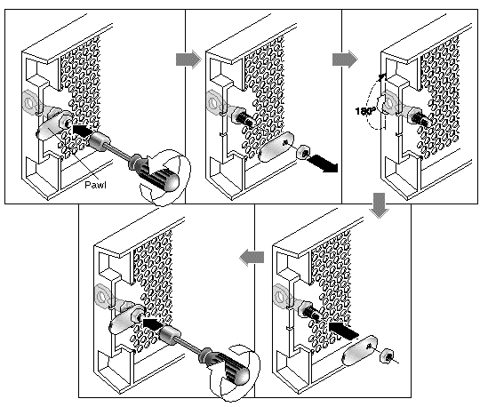
1. Remove the bezel by gently pivoting the swing arms out of their ear sockets, and make sure the key is in the locked position, with the pawl extending horizontally past the edge of the bezel (see the first panel of FIGURE 1-2).
2. Hold the key in place and use a 12-mm or 3/8-inch nut driver to remove the locking nut that holds the pawl in place, as shown in the first panel of FIGURE 1-2.

|
Caution - Be sure to hold the key in place. Otherwise there is a risk of breaking the small tab on the lock that serves as a stop. |
3. Lift the pawl off the threaded part of the lock body, as shown in the second panel of FIGURE 1-2.
4. Set the pawl aside, face up, so that you can remember its orientation when you replace it.
5. Use the key to turn the lock 180 degrees, as shown in the third panel of FIGURE 1-2
6. Replace the pawl in the same orientation as before, as shown in the fourth panel of FIGURE 1-2.
7. Hold the key in place and use the nut driver to refasten the locking nut that holds the pawl in place, as shown in the fifth panel of FIGURE 1-2. Be careful not to cross-thread the nut.


|
Caution - Be sure to hold the key in place. Otherwise there is a risk of breaking the small tab on the lock that serves as a stop. |
|
Note - To convert your bezel locks back so that the keys can be removed, repeat the preceding steps. |
Copyright © 2006, Dot Hill Systems Corporation and others. All rights reserved.