Sun Blade 6000 Virtualized
Multi-Fabric 10GbE Network Express Module User’s Guide 6000 Virtualized
Multi-Fabric 10GbE Network Express Module User’s Guide |
| C H A P T E R 1 |
The Sun Blade 6000 Virtualized Multi-Fabric 10GbE Network Express Module (NEM) is a multi-purpose connectivity module for the Sun Blade 6000 modular system. The NEM supports connection to external devices through 10 GigabitEthernet (GbE) small form-factor pluggable (SFP)+ ports and 10/100/1000 twisted-pair Ethernet (TPE) ports and connects server modules (blades) in a Sun Blade 6000 modular system chassis with disk modules in the same chassis.
This chapter includes the following sections:
Overview of the Virtualized Multi-Fabric 10GbE NEM Components
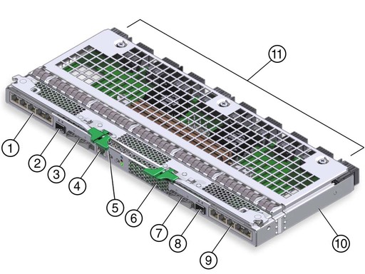
Physical Appearance of the Virtualized Multi-Fabric 10GbE NEM
Note - If you have not already read the Sun Blade 6000 Disk Module Configuration Guide, you should do so before proceeding with this manual. |
The following terms are used in this document:
| chassis | The Sun Blade 6000 Modular System blade enclosure. |
| disk module (or disk blade) | The Sun Blade 6000 Disk Module. The terms disk module and disk blade are used interchangeably. |
| server module (or server blade) | Any server module (blade) that will interoperate with a disk module (blade). Examples are the Sun Blade X6220, X6240, X6250, X6440, X6450, T6300, and T6320 server modules. The terms server module and server blade are used interchangeably. |
| Virtualized NEM | The Sun Blade 6000 Virtualized Multi-Fabric 10GbE Network Express Module that plugs into a Sun Blade 6000 chassis (abbreviated Virtualized Multi-Fabric 10GbE NEM). |
| Virtualized NEM ASIC | A shortened reference to the ASICs embedded in the Sun Blade 6000 Virtualized Multi-Fabric 10GbE Network Express Module that enable 10GbE virtualization. |
| Multi-Fabric NEM | A generic term that applies to any Network Express Module that provides a variety of interconnect options to server blades in a chassis. The Virtualized Multi-Fabric 10GbE NEM is one example. |
| SAS NEM | A generic term that applies to any Network Express Module that supports SAS connectivity. The Virtualized Multi-Fabric 10GbE NEM is one example of a SAS NEM. |
| NEM 0, NEM 1 | Terms used by NEM management software to identify Multi-Fabric NEMs occupying NEM slots in the chassis. |
| 10 GbE | 10 Gigabit Ethernet. |
The key features of the Virtualized Multi-Fabric 10GbE NEM are listed in TABLE 1-1.
This section describes the major components of the Virtualized Multi-Fabric 10GbE NEM.
The following topics are covered in this section:
Each Virtualized Multi-Fabric 10GbE NEM has 10 SAS x2 connections to the modules in the chassis through the chassis mid-plane. There is one SAS x2 connection for each module slot. External SAS connections are not currently supported.
One of the functions of the Virtualized Multi-Fabric 10GbE NEM SAS expander is to provide zoning for the disks that are visible to the server modules in the chassis. This includes disks on the server modules, disks on disk modules, and external disks. Firmware on the Virtualized Multi-Fabric 10GbE NEM SAS expander controls zoning (that is, which disks can be seen by each individual server module).
The default zoning is such that the server modules and disk modules must be placed in the chassis in pairs. The pairs can be in slots 0+1, 2+3, 4+5, 6+7, or 8+9. Other pairings, such as 1+2 or 5+6, do not couple the server and storage modules.
Thus, in the recommended use of default zoning, a server module in an even-numbered slot, n, sees all the disks in slot n+1, but no other disks. FIGURE 1-1 shows the default zoning configuration for server modules and disk modules.
FIGURE 1-1 Schematic of Chassis With Server Modules (Processor Blades) and Disk Modules (Disk Blades) in the Default Paired Zoning
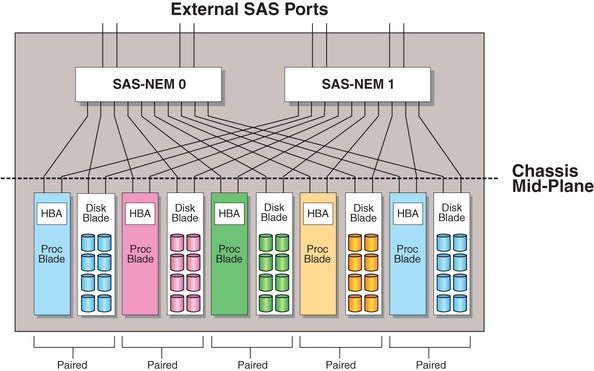
The disk module that connects to a server module in slot n (where n = 0, 2, 4, 6, or 8) must be in slot n+1.
Note - A server module that is not paired with a disk module works in any slot. |
For more information on the Sun Blade 6000 disk module, refer to the documentation site at: (http://docs.sun.com/app/docs/prod/blade.6000disk#hic)
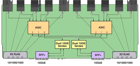
The Virtualized Multi-Fabric 10GbE NEM provides the magnetics and RJ-45 connectors for the ten 10/100/1000 BASE-T Ethernet interfaces that come from Sun Fire 6000 server modules through the midplane. The Sun Blade 6000 Virtualized Multi-Fabric 10GbE NEM has one 10/100/1000BASE-T Ethernet port for each server module slot. There is no active circuitry on the Virtualized Multi-Fabric 10GbE NEM for these GbE ports.
The Virtualized Multi-Fabric 10GbE NEM also provides a 10 GbE connection for each server module. Each server module appears to have its own 10 GbE NIC through the Virtualized NEM ASICs. All the server modules share two physical small form-factor pluggable (SFP+) 10 GbE ports via a dual channel 10 GbE Serializer/Deserializer (SerDes) per ASIC. In a Sun Blade 6000 chassis, five server modules connect to a single Virtualized NEM ASIC and share its 10 GbE port. Two Virtualized NEM ASICs can be configured so that the ten server modules share one 10 GbE port for simplified cable aggregation.
See 10 GbE NIC Virtualization for further information on the NEM 10 GbE virtualization.
FIGURE 1-2 shows a schematic of the NEM Ethernet connections.
This section provides information on the 10 GbE NIC functionality for the Virtualized Multi-Fabric 10GbE NEM.
This section covers the following topics:
The Virtualized NEM ASIC allows up to five hosts to share a single 10 GbE network port, with a dedicated PCIe endpoint for each host.
Shared I/O allows each server module to work as if a dedicated NIC connects the server module to the network. Each server module owns a virtual MAC that provides per-server-module statistics on Rx/Tx traffic. The MAC that interfaces to the 10 GbE network port is shared and is hidden from the server modules. Only the service processor can access and configure this port.
A Virtualized Multi-Fabric 10GbE NEM contains two Virtualized NEM ASICs, which can operate in two different modes:
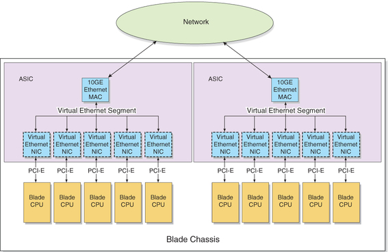
The Virtualized NEM ASICs can operate in bandwidth mode where the Virtualized NEM ASICs act without knowledge of each other or connectivity (IAL) mode where all server modules share a single 10GbE uplink. Each ASIC provides 10 GbE network access for the five hosts attached to it.
FIGURE 1-3 shows how the ASICs operate in bandwidth mode.
Two Virtualized NEM ASICs can also be interconnected so that a single 10 GbE port can act as the shared I/O for 10 server modules (connectivity mode). The inter-ASIC link (IAL) extends the virtual Ethernet segment to all the server modules. An illustration of this configuration is shown in FIGURE 1-4.
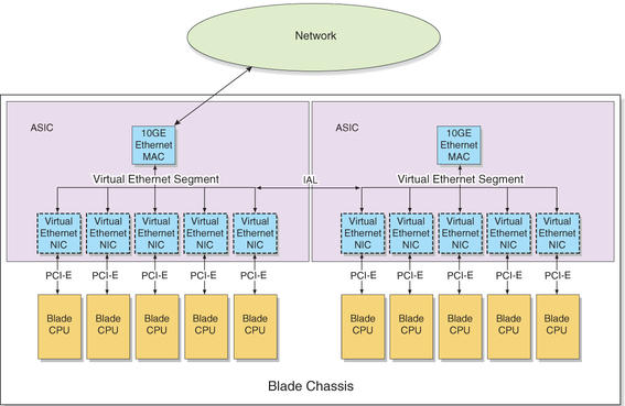
Because of the symmetry of the IAL, either Virtualized NEM ASIC can be connected to the external network. This configuration can be used for higher aggregation per 10 GbE port (1x10 GbE for 10 server modules).
The IAL is enabled or disabled due to a combination of two different factors:
Whether or not the NEM has dynamic mode enabled
Refer to TABLE 1-2 for more information on IAL.
TABLE 1-2 explains the IAL functionality:
Refer to Enable or Disable IAL Dynamic Mode for instructions on how to enable dynamic mode through the NEM service processor.
For example, in the following scenario, IAL will be dynamically disabled:
The five server modules attached to the ASIC that is connected to the new SFP+ module will lose 10GbE connectivity unless a fiber optic cable is connected to the new SFP+ connector.
For some server modules to access the 10 GbE functionality of the Virtualized Multi-Fabric 10GbE NEM, they must have a fabric express module (FEM) installed in the server module. TABLE 1-3 shows which FEMs are required for each server module. Refer to the Virtualized NEM product web pages on (http://sun.com) for updates to the list of FEMs required for the server modules.
| Server Blade Module | FEM Part Number |
|---|---|
| T6300 | FEM not needed |
| T6320 | X4835A |
| T6340 | X4835A |
| X6220 | FEM not needed |
| X6240 | X4263A |
| X6250 | X4681A |
| X6440 | X4263A |
| X6450 | X4681A |
The Virtualized Multi-Fabric 10GbE NEM has an Aspeed AST2000 controller as its service processor (SP), which is responsible for the control and management of the Virtualized NEM ASICs. The NEM also has a 10/100BASE-T Ethernet management port for connectivity to the Sun Blade 6000 CMM.
The following list describes the features of the service processor:
The AST2000 controller has a 200MHz ARM9 CPU core and a rich set of features and interfaces. The BCM5241 receives a 25MHz reference clock.
A Broadcom BCM5241 10/100BASE-T Ethernet PHY connected to the AST2000 controller’s 10/100M Fast Ethernet MAC provides the Ethernet management interface to the CMM.
The SP can update Sun Blade 6000 Virtualized Multi-Fabric 10GbE NEM FPGA and firmware using GPIOs connected to the JTAG port of the FPGA.
Refer to Appendix B for more information on the Integrated Lights Out Manager (ILOM) server management application for the SP.
FIGURE 1-5 shows an overview of the Virtualized Multi-Fabric 10GbE NEM.
This section describes the external ports on the NEM.
There are 10 pass-through RJ-45 Gigabit Ethernet ports on the Virtualized Multi-Fabric 10GbE NEM. The pass-through Gigabit Ethernet ports are strictly passive and isolated from the other functional blocks, with no interaction.
FIGURE 1-6 shows the NEM front panel and LEDs, viewed from the back of the chassis. TABLE 1-5 describes the LED behavior.
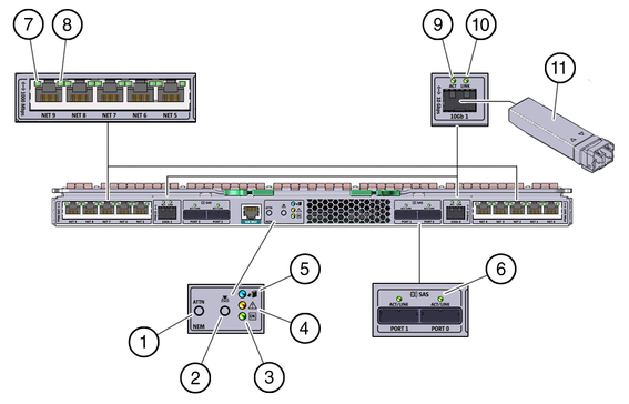
| LED/Button Name | Description | |
|---|---|---|
| 1 | Attention button | Not currently supported. |
| 2 | Locate button and LED (white) | Helps locate each NEM. |
| 3 | Module Activity (Power/OK) LED (green) | Has three states: |
| 4 | Module Fault LED (amber) | Has two states: |
| 5 | OK-to-Remove LED (blue) | Not currently supported. |
| 6 | SAS Activity | Not currently supported. |
| 7/ 8 | Activity/Link for 10/100/1000 MbE | See TABLE 1-6. |
| 9/10 | Activity/Link for 10 GbE connection | The left green LED is for network activity
status. It blinks on and off when there is network activity.
The right green LED is for network link status. It is steady on when a 10GbE link is reached. |
| 11 | SFP+ Module | SFP+ modules are needed for 10GbE connectivity. |
Each RJ45 Ethernet port has two LEDs. The left LED is green and lights to show that a link has been established. It blinks off randomly whenever there is network activity on that port.
On the RJ-45 connectors, the right LED is bi-color (amber and green) and indicates the speed of connection by the color it displays. When the port is operating at 100 megabits per second, the right LED displays one color. When operating at 1000 megabits per second, it displays the other color. When operating at 10 megabits per second, the right LED is off. The green/amber color scheme varies from one server blade to another. TABLE 1-6 provides a chart for interpreting the link-speed relationships.
When an Ethernet port is connected to an x64 server blade (server blades with a model number that starts with X) that has been put in Wake-on-LAN (WOL) mode, the Link LED indicates when the system is in standby mode. It does this by blinking in a repeating, non-random pattern. It flashes ON for 0.1 second and OFF for 2.9 seconds. In standby mode, the system is functioning at a minimal level and is ready to resume full activity.
Note - SPARC-based server blades do not support the WOL mode. When an Ethernet port is connected to a SPARC server blade, the Link LED behaves as described in TABLE 1-6. SPARC-based blades are designated by a T in front of the server module number (for example, T6300). |
Copyright © 2009, Sun Microsystems, Inc. All rights reserved.