Chapter 4 Making the Transition From IPv4 to IPv6 (Reference)
When hosts and routers are upgraded to IPv6, these nodes now have to interoperate with the IPv4 hosts and IPv4 routers. This chapter provides an overview of the standardized solutions to make the transition from IPv4 to IPv6. RFC 1933 also provides detailed solutions to the transition problem.
This chapter contains the following information:
Transition Requirements
The transition does not require any global coordination. Your sites and Internet service provider (ISP) can transition at their own pace. Furthermore, an effort has been made to minimize the number of dependencies during the transition. For instance, the transition does not require that routers be upgraded to IPv6 prior to upgrading hosts.
Different sites have different constraints during the transition process. Also, early adopters of IPv6 are likely to have different concerns than production users of IPv6. RFC 1933 defines the transition tools currently available. The rationale for transition is either the lack of IPv4 address space or the required use of new features in IPv6, or both. The IPv6 specification requires 100 per cent compatibility for the existing protocols. Compatibility is also required for existing applications during the transition.
To understand the transition approaches, the following terms have been defined.
-
IPv4-only node – A host or router that implements only IPv4. An IPv4-only node does not understand IPv6. The installed base of IPv4 hosts and routers that exist before the transition begins are IPv4-only nodes.
-
IPv6/IPv4 node – A host or router that implements both IPv4 and IPv6, which is also known as dual-stack.
-
IPv6-only node – A host or router that implements IPv6, and does not implement IPv4.
-
IPv6 node – Any host or router that implements IPv6. IPv6/IPv4 and IPv6-only nodes are both IPv6 nodes.
-
IPv4 node – Any host or router that implements IPv4. IPv6/IPv4 and IPv4-only nodes are both IPv4 nodes.
-
6to4 router – Any boundary router that is configured with a 6to4 pseudo-interface on its IPv4 network connection. A 6to4 router serves as an endpoint of a 6to4 tunnel, over which the router forwards packets to another IPv6 site.
-
6to4 host – Any IPv6 host with an interface that is configured with a 6to4–derived address.
-
Site – Piece of the private topology of the Internet that does not carry transit traffic for anybody and everybody. The site can span a large geographic area. For instance, the private network on a multinational corporation is one site.
Standardized Transition Tools
RFC 1933 defines the following transition mechanisms:
-
When you upgrade your hosts and routers to IPv6, the hosts and routers retain their IPv4 capability. Consequently, IPv6 provides compatibility for all IPv4 protocols and applications. These hosts and routers are known as dual-stack.
-
These hosts and routers use the name service, for example, DNS, to carry information about which nodes are IPv6 capable.
-
IPv6 address formats can contain IPv4 addresses.
-
You can tunnel IPv6 packets in IPv4 packets as a method of crossing routers that have not been upgraded to IPv6.
Implementing Dual-Stack
The term dual-stack normally refers to a complete duplication of all levels in the protocol stack from applications to the network layer. An example of complete duplication is the OSI and TCP/IP protocols that run on the same system. However, in the context of IPv6 transition, dual-stack means a protocol stack that contains both IPv4 and IPv6. The remainder of the stack is identical. Consequently, the same transport protocols, TCP, UDP, and so on, can run over both IPv4 and IPv6. Also, the same applications can run over both IPv4 and IPv6.
The following figure illustrates dual-stack protocols through the OSI layers.
Figure 4–1 Dual-Stack Protocols
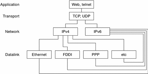
In the dual-stack method, subsets of both hosts and routers are upgraded to support IPv6, in addition to IPv4. The dual-stack approach ensures that the upgraded nodes can always interoperate with IPv4-only nodes by using IPv4.
Configuring Name Services
A dual node must determine if the peer can support IPv6 or IPv4 in order to check which IP version to use when transmitting. The control of the information that goes in the name service enables a dual node to determine which IP version to use. You define an IPv4 node's IP address and the IPv6 node's IP address in the name service. Thus, a dual node has both addresses in the name service.
The presence of an IPv6 address in the name service also signifies that the node is reachable by using IPv6. However, the node is only reachable by nodes that obtain information from that name service. For example, placing an IPv6 address in NIS implies that the IPv6 host is reachable by using IPv6. However, the IPv6 host is only reachable by IPv6 and dual nodes that belong to that NIS domain. The placement of an IPv6 address in global DNS requires that the node is reachable from the Internet IPv6 backbone. This situation is no different than in IPv4. For example, the mail delivery operation requires that IPv4 addresses exist for nodes that can be reached by using IPv4. The same situation is true for the HTTP proxy operation. When no reachability exists in IPv4, for instance, because of firewalls, the name service must be partitioned into an inside firewall and outside firewall database. Consequently, the IPv4 addresses are visible only where the IPv4 addresses are reachable.
The protocol that is used to access the name service is independent of the type of address that can be retrieved from the name service. This name service support, and dual-stacks, enables a dual node to use IPv4 when the dual node communicates with IPv4-only nodes. Also, this name service support enables a dual node to use IPv6 when the dual node communicates with IPv6 nodes. However, the destination must be reachable through an IPv6 route.
Using IPv4-Compatible Address Formats
In many instances, you can represent a 32-bit IPv4 address as a 128-bit IPv6 address. The transition mechanism defines the following two formats.
-
IPv4–compatible address
000 ... 000
IPv4 Address
-
IPv4–mapped address
000 ... 000
0xffff
IPv4 Address
The compatible format is used to represent an IPv6 node. This format enables you to configure an IPv6 node to use IPv6 without having a real IPv6 address. This address format enables you to experiment with different IPv6 deployments because you can use automatic tunneling to cross IPv4–only routers. However, you cannot configure these addresses by using the IPv6 stateless address autoconfiguration mechanism. This mechanism requires existing IPv4 mechanisms such as DHCPv4 or static configuration files.
The mapped address format is used to represent an IPv4 node. The only currently defined use of this address format is part of the socket API. An application can have a common address format for both IPv6 addresses and IPv4 addresses. The common address format can represent an IPv4 address as a 128-bit mapped address. However, IPv4–to-IPv6 protocol translators also allow these addresses to be used.
Tunneling Mechanism
To minimize any dependencies during the transition, all the routers in the path between two IPv6 nodes do not need to support IPv6. This mechanism is called tunneling. Basically, IPv6 packets are placed inside IPv4 packets, which are routed through the IPv4 routers. The following figure illustrates the tunneling mechanism through IPv4 routers (R).
Figure 4–2 Tunneling Mechanism
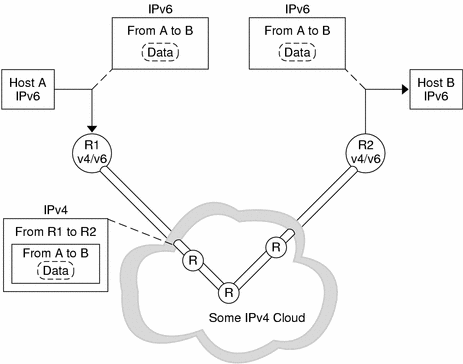
The different uses of tunneling in the transition follow:
-
Configured tunnels between two routers, as in the previous figure
-
Automatic tunnels that terminate at the dual hosts
A configured tunnel is currently used in the Internet for other purposes, for example, the MBONE, the IPv4 multicast backbone. Operationally, the tunnel consists of two routers that are configured to have a virtual point-to-point link between the two routers over the IPv4 network. This kind of tunnel is likely to be used on some parts of the Internet for the foreseeable future.
Automatic Tunnels
Note –
The preferred method for creating automatic tunnels is through 6to4 tunneling. For detailed information about the 6to4 routing and tunneling mechanism, refer to 6to4 as a Transition Mechanism.
Automatic tunnels require IPv4–compatible addresses. Automatic tunnels can be used to connect IPv6 nodes when IPv6 routers are not available. These tunnels can originate either on a dual host or on a dual router by configuring an automatic tunneling network interface. The tunnels always terminate on the dual host. These tunnels work by dynamically determining the destination IPv4 address, the endpoint of the tunnel, by extracting the address from the IPv4–compatible destination address.
Interaction With Applications
Even on a node that has been upgraded to IPv6, the use of IPv6 is dependent on the applications. An application might not use a networking API that asks the name service for IPv6 addresses. The application might use an API, such as sockets, which requires changes in the application. Also, the provider of the API, such as an implementation of the java.net class might not support IPv6 addresses. In either situation, the node only sends and receives IPv4 packets like an IPv4 node would.
The following names have become standard terminology within the Internet community:
-
IPv6–unaware—This application cannot handle IPv6 addresses. This application cannot communicate with nodes that do not have an IPv4 address.
-
IPv6–aware—This application can communicate with nodes that do not have an IPv4 address, that is, the application can handle the larger IPv6 addresses. In some situations, the address might be transparent to the application, for example, when the API hides the content and format of the actual address.
-
IPv6–enabled—This application can, in addition to being IPv6–aware, can use some IPv6–specific feature such as flow labels. The enabled applications can still operate over IPv4, though in a degraded mode.
-
IPv6–required—This application requires some IPv6–specific feature. This application cannot operate over IPv4.
IPv4 and IPv6 Interoperability
During the gradual transition phase from IPv4 to IPv6, existing IPv4 applications must continue to work with newer IPv6–enabled applications. Initially, vendors provide host and router platforms that are running a dual-stack. A dual-stack is both an IPv4 protocol stack and an IPv6 protocol stack. IPv4 applications continue to run on a dual– stack that is also IPv6 enabled with at least one IPv6 interface. No changes need to be made to these applications, no porting required.
IPv6 applications that run on a dual-stack can also use the IPv4 protocol. IPv6 applications use an IPv4-mapped IPv6 address. Because of the design of IPv6, separate applications, IPv4 and IPv6, are not needed. For example, you do not need an IPv4 client on a dual host to “talk” with a server on an IPv4-only host. Also, you do not need a separate IPv6 client to talk with an IPv6 server. You need only to port their IPv4 client application to the new IPv6 API. The client can communicate with IPv4–only servers. The client can also communicate with IPv6 servers that run on either a dual host or an IPv6–only host.
The address that the client receives from the name server determines if IPv6 or IPv4 is used. For example, if the name server has an IPv6 address for a server, then the server runs IPv6.
The following table summarizes the interoperability between IPv4 and IPv6 clients and servers. The table assumes that the dual-stack host has both an IPv4 and IPv6 address in the respective name service database.
Table 4–1 Client-Server Applications: IPv4 and IPv6 Interoperability|
Type of Application (Type of Node) |
IPv6-Unaware Server (IPv4-Only Node) |
IPv6-Unaware Server (IPv6-Enabled Node) |
IPv6-Aware Server (IPv6-Only Node) |
IPv6-Aware Server (IPv6-Enabled Node) |
|---|---|---|---|---|
|
IPv6-unaware client (IPv4-only node) |
IPv4 |
IPv4 |
X |
IPv4 |
|
IPv6-unaware client (IPv6-enabled node) |
IPv4 |
IPv4 |
X |
IPv4 |
|
IPv6-aware client (IPv6-only node) |
X |
X |
IPv6 |
IPv6 |
|
IPv6-aware client (IPv6-enabled node) |
IPv4 |
(IPv4) |
IPv6 |
IPv6 |
X means that the server cannot communicate with the client.
(IPv4) denotes that the interoperability depends on the address that is chosen by the client. If the client chooses an IPv6 address, the client fails. However, an IPv4 address that is returned to the client as an IPv4–mapped IPv6 address causes an IPv4 datagram to be sent successfully.
In the first phase of IPv6 deployment, most implementations of IPv6 are on dual-stack nodes. Initially, most vendors do not release IPv6–only implementations.
Site Transition Scenarios
Each site and each ISP requires different steps during the transition phase. This section provides some examples of site transition scenarios.
The first step to transition a site to IPv6 is to upgrade the name services to support IPv6 addresses. For DNS, upgrade to a DNS server that supports the new AAAA (quad-A), such as BIND 4.9.4 and later. Two new NIS maps and a new NIS+ table have been introduced for storing IPv6 addresses. The new NIS maps and new NIS+ table can be created and administered on any Solaris system. See IPv6 Extensions to Solaris Name Services for details on the new databases.
After the name service is able to distribute IPv6 addresses, you can start transitioning hosts. You can transition hosts in the following ways:
-
Upgrade one host at a time. Use IPv4–compatible addresses and automatic tunneling. No routers need to be upgraded. Use this method for initial experimental transition. This method offers only a subset of the IPv6 benefits. This method does not offer stateless address autoconfiguration or IP multicast. You can use this scenario to verify that applications work over IPv6. This scenario also verifies that the application can use IPv6 IP-layer security.
-
Upgrade one subnet at a time. Use configured tunnels between the routers. In this scenario, at least one router per subnet is upgraded to dual. The dual routers in the site are tied together by using configured tunnels. Then, hosts on those subnets can use all the IPv6 features. As more routers become upgraded in this incremental scheme, you can remove the configured tunnels.
-
Upgrade all the routers to dual before any host is upgraded. Though this method appears orderly, the method does not provide any IPv6 benefits until all the routers have been upgraded. This scenario constrains the incremental deployment approach.
6to4 as a Transition Mechanism
The Solaris operating system includes 6to4 as a preferred interim method for making the transition from IPv4 to IPv6 addressing. 6to4 enables isolated IPv6 sites to communicate across an automatic tunnel over an IPv4 network that does not support IPv6. To use 6to4 tunnels, you must configure a boundary router on your IPv6 network as one endpoint of the 6to4 automatic tunnel. Thereafter, the 6to4 router can participate in a tunnel to another 6to4 site, or, if required, to a native IPv6, non-6to4 site.
This section provides reference materials on the following 6to4 subjects:
-
Topology of the 6to4 tunnel
-
6to4 addressing, including the format of the advertisement
-
Description of packet flow across a 6to4 tunnel
-
Topology of a tunnel between a 6to4 router and 6to4 relay router
-
Points to consider before you configure 6to4 relay router support.
More information about 6to4 routing is available from the following sources.
|
Task or Detail |
For Information |
|---|---|
|
Overview of 6to4 routing | |
|
Tasks for configuring a 6to4 site | |
|
6to4 related RFC, “Connection of IPv6 Domains via IPv4 Clouds” | |
|
Detailed information about the 6to4relay command, which enables support for tunnels to a 6to4 relay router |
6to4relay(1M) man page |
|
6to4 security issues Internet Draft, “Security Considerations for 6to4” |
Participants in a 6to4 Tunnel
The following figure shows a 6to4 tunnel between two 6to4 sites.
Figure 4–3 Tunnel Between Two 6to4 Sites
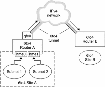
The figure depicts two isolated 6to4 networks, Site A and Site B. Each site has configured a router with an external connection to an IPv4 network. In the figure, a 6to4 tunnel across the IPv4 network connects the 6to4 sites.
Before an IPv6 site can become a 6to4 site, you must configure at least one router interface for 6to4 support. This interface must provide the external connection to the IPv4 network. The address that you configure on qfe0 must be globally unique. In the previous figure, boundary Router A's interface qfe0 connects Site A to the IPv4 network. Interface qfe0 must already be configured with an IPv4 address before you can configure qfe0 as a 6to4 pseudo-interface.
In the figure, 6to4 Site A is composed of two subnets, which are connected to interfaces hme0 and hme1 on Router A. All IPv6 hosts on either subnet of Site A automatically reconfigure with 6to4–derived addresses on receipt of the advertisement from Router A.
Site B is the opposite endpoint of the tunnel from Site A. To correctly receive traffic from Site A, a boundary router on Site B must be configured for 6to4 support. Otherwise, packets that the router receives from Site A are not recognized and dropped.
6to4-Derived Addressing
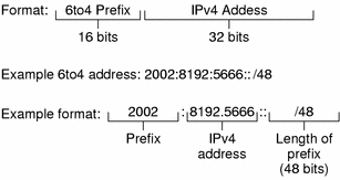
As with native IPv6 routers, you must advertise the subnet prefixes derived from the site 6to4 prefix in /etc/inet/ndpd.conf. The next figure shows the parts of a prefix for a 6to4 site, as described in 6to4 Prefix Format and 6to4 Advertisement Example.
Figure 4–4 Parts of a Site Prefix
The next figure shows the parts of a subnet prefix for a 6to4 site, such as you would include in the ndpd.conf file.
Figure 4–5 Parts of a Subnet Prefix
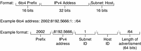
6to4 Prefix Format
The format line in the previous figure contains the following parts.
|
Part |
Length |
Definition |
|---|---|---|
|
Prefix |
16 bits |
6to4 prefix 2002 (0x2002). |
|
IPv4 address |
32 bits |
Unique IPv4 address that is already configured on the 6to4 interface. For the advertisement, you specify the hexadecimal representation of the IPv4 address, rather than the IPv4 dotted–decimal representation. |
|
Subnet ID |
16 bits |
Subnet ID, which must be a value that is unique for the link at your 6to4 site. |
6to4 Advertisement Example
The example in the previous figure has the following values.
|
Advertisement Part |
Corresponding Value |
|---|---|
|
6to4 prefix |
2002 |
|
IPv4 address |
8192:56bb, which corresponds to IPv4 address 129.146.87.188 |
|
Subnet ID |
1 |
|
/64 |
Length of prefix |
6to4-Derived Addressing on a Host
When an IPv6 host receives the 6to4–derived prefix by way of a router advertisement, the host automatically reconfigures a 6to4–derived address on an interface. The address has the following form.
prefix:IPv4 address:subnet ID:host ID/64 |
The results of ifconfig –a on a host with a 6to4 interface might resemble the following:
qfe1:3: flags=2180841<UP,RUNNING,MULTICAST,ADDRCONF,ROUTER,IPv6>
 mtu 1500 index 7
        inet6 2002:8192:56bb:9258:a00:20ff:fea9:4521/64
|
The 6to4–derived address follows inet6 in the output from ifconfig.
|
Address Part |
Corresponding Value |
|---|---|
|
Prefix |
2002, which is the 6to4 prefix |
|
IPv4 value |
8192:56bb, which is the IPv4 address, in hexadecimal notation, for the 6to4 pseudo-interface that is configured on the 6to4 router |
|
subnet ID |
9258, which is the address of the subnet of which this host is a member |
|
MAC address |
a00:20ff:fea9:4521, which is the link layer address of the host interface that is now configured for 6to4 |
Packet Flow Through the 6to4 Tunnel
This section describes the path of packets from a host at one 6to4 site to a host in a remote 6to4 site. The next scenario uses the topology that is shown in Figure 4–3 as its example. Moreover, the scenario assumes that the 6to4 routers and 6to4 hosts are already configured.
-
A host on Subnet 1 of 6to4 Site A sends a transmission, with a host at 6to4 Site B as the destination. Each packet header in the flow has a source 6to4–derived address and destination 6to4– derived address.
-
6to4 Router A receives the outgoing packets and creates a tunnel over an IPv4 network to 6to4 Site B.
-
Site A's router encapsulates each 6to4 packet into an IPv4 header. Then the router uses standard IPv4 routing procedures to forward the packet over the IPv4 network.
-
Any IPv4 routers that the packets encounter use the packets' destination IPv4 address for forwarding. This address is the globally unique IPv4 address of the interface on Router B, which also serves as the 6to4 pseudo-interface.
-
Packets from Site A arrive at Router B, which decapsulates the IPv6 packets from the IPv4 header.
-
Router B then uses the destination address in the IPv6 packet to forward the packets to the recipient host at Site B.
Considerations for Tunnels to a 6to4 Relay Router
6to4 relay routers function as endpoints for tunnels from 6to4 routers that need to communicate with native IPv6, non-6to4 networks. Relay routers are essentially bridges between the 6to4 site and native IPv6 sites. Because this solution is very insecure, by default the Solaris operating system does not enable 6to4 relay router support. However, if your site requires such a tunnel, you use the 6to4relay command to enable the following tunneling scenario.
Figure 4–6 Tunnel From a 6to4 Site to a 6to4 Relay Router
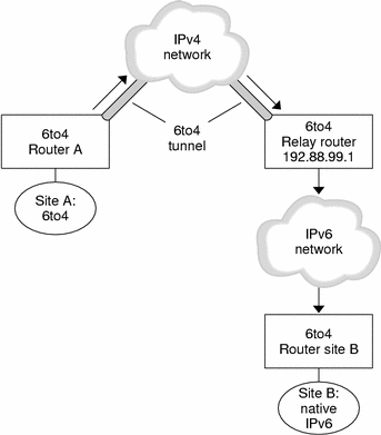
In Figure 4–6 , 6to4 Site A needs to communicate with a node at native IPv6 Site B. The figure shows the path of traffic from Site A onto a 6to4 tunnel over an IPv4 network. The tunnel has 6to4 Router A and a 6to4 relay router as its endpoints. Beyond the 6to4 relay router is the IPv6 network, to which IPv6 Site B is connected.
Packet Flow Between a 6to4 Site and Native IPv6 Site
This section describes the flow of packets from a 6to4 site to a native IPv6 site. The text uses the scenario that is shown in Figure 4–6 as an example.
-
A host on 6to4 Site A sends a transmission that specifies as the destination a host at native IPv6 Site B. Each packet header in the flow has a 6to4–derived address as its source address. The destination address is a standard IPv6 address.
-
6to4 Router A receives the outgoing packets and creates a tunnel over an IPv4 network to a 6to4 relay router.
6to4 relay routers that are part of the 6to4 relay router anycast group have the address 192.88.99.1. This anycast address is the default address for 6to4 relay routers. If you need to use a specific 6to4 relay router, you can override the default and specify that router's IPv4 address.
-
Site A's 6to4 router encapsulates each packet into a IPv4 header, which has the IPv4 address of the 6to4 relay router as its destination. The 6to4 router uses standard IPv4 routing procedures to forward the packet over the IPv4 network. Any IPv4 routers that the packets encounter forward the packets to the 6to4 relay router.
-
The physically closest anycast 6to4 relay router to Site A retrieves the packets that are destined for the 192.88.99.1 anycast group.
-
The relay router decapsulates the IPv4 header from the 6to4 packets, revealing the native IPv6 destination address.
-
The relay router then sends the now IPv6–only packets onto the IPv6 network, where the packets are ultimately retrieved by a router at Site B. The router then forwards the packets to the destination IPv6 node.
Security Issues for 6to4 Relay Router Support
By nature, a tunnel between a 6to4 router and 6to4 relay router is insecure. Security problems, such as the following, are inherent in such a tunnel.
-
Though 6to4 relay routers do encapsulate and decapsulate packets, these routers do not check the data that is contained within the packets.
-
Address spoofing is a major issue on tunnels to a 6to4 relay router. For incoming traffic, the 6to4 router is unable to match the IPv4 address of the relay router with the IPv6 address of the source. Therefore, the address of the IPv6 host can easily be spoofed. The address of the 6to4 relay router can also be spoofed.
-
By default, no trust mechanism exists between 6to4 routers and 6to4 relay routers. Thus, a 6to4 router cannot identify whether the 6to4 relay router is to be trusted, or even a legitimate 6to4 relay router. A trust relationship between the 6to4 site and the IPv6 destination must exist, or the both sites leave themselves open to possible attacks.
These problems and other security issues that are inherent with 6to4 relay routers are explained in Internet Draft Security Considerations for 6to4. Generally, you should consider enabling support for 6to4 relay routers only for the following reasons:
-
Your 6to4 site intends to communicate with a private, trusted IPv6 network. For example, you might enable 6to4 relay router support on a campus network that consists of isolated 6to4 sites and native IPv6 sites.
-
Your 6to4 site has a compelling business reason to communicate with certain native IPv6 hosts.
-
You have implemented the checks and trust models that are suggested in Internet Draft, Security Considerations for 6to4.
Known Issues With 6to4 Router
The following known bugs affect 6to4 configuration:
-
4709338 – Need a RIPng implementation which recognizes static routes
-
4152864 – Configuring two tunnels with the same tsrc/tdst pair works
Implementing Static Routes at the 6to4 Site (BugID 4709338)
The following issue occurs on 6to4 sites with routers that are internal to the 6to4 boundary router. When you configure the 6to4 pseudo-interface, the static route 2002::/16 is automatically added to the routing table on the 6to4 router. Bug 4709338 describes a limitation in the Solaris RIPng routing protocol that prevents this static route from being advertised to the 6to4 site.
Either of the following work arounds are available for Bug 4709338.
-
Add the 2002::/16 static route to the routing tables of all intra-site routers within the 6to4 site.
-
Use a routing protocol other than RIPng on the 6to4 site's internal router.
Configuring Tunnels with the Same Source Address (BugID 4152864)
Bug ID 4152864 describes problems that occur when two tunnels are configured with the same tunnel source address, which is a serious issue for 6to4 tunnels.
Do not configure a 6to4 tunnel and an automatic tunnel with the same tunnel source address.
Other Transition Mechanisms
The mechanisms that were specified previously handle interoperability between dual nodes and IPv4 nodes, if the dual nodes have an IPv4 address. The mechanisms do not handle interoperability between IPv6-only nodes and IPv4-only nodes. Also, the mechanisms do not handle interoperability between dual nodes that have no IPv4 address and IPv4-only nodes. Most implementations can be made dual. However, a dual implementation requires enough IPv4 address space to assign one address for every node that needs to interoperate with IPv4-only nodes.
Several possibilities enable you to accomplish this interoperability without requiring any new transition mechanisms.
-
Use application layer gateways (ALG) that sit at the boundary between the IPv6-only nodes and the remainder of the Internet. Examples of ALGs in use today are HTTP proxies and mail relays.
-
Companies are already selling network address translators (NAT) boxes for IPv4. The NAT boxes translate between the private IP addresses, for example, network 10—see RFC 1918, on the inside and other IP addresses on the outside. These companies will likely upgrade their NAT boxes to also support IPv6–to-IPv4 address translation.
Unfortunately, both ALG and NAT solutions create single points of failure. By using these solutions, the Internet becomes less effective. The IETF is working on a better solution for IPv6-only interoperability with IPv4-only nodes. One proposal is to use header translators with a way to allocate IPv4–compatible addresses on demand. Another proposal is to allocate IPv4–compatible addresses on demand and use IPv4 in IPv6 tunneling to bridge the IPv6-only routers.
The stateless header translator translates between IPv4 and IPv6 header formats if the IPv6 addresses in use can be represented as IPv4 addresses. The addresses must be IPv4-compatible. Or, the addresses must be IPv4-mapped addresses. The support for these translators has been built into the IPv6 protocol. The translation can occur without any information loss, except for encrypted packets. Rarely used features such as source routing can produce information loss.
- © 2010, Oracle Corporation and/or its affiliates
