| C H A P T E R 3 |
|
Connecting the Sun StorageTek 5320 NAS Appliance |
This chapter provides comprehensive instructions for connecting the Sun StorageTek 5320 NAS Appliance, the Sun StorEdge 5300 RAID Controller Enclosures, and the optional Sun StorEdge 5300 Expansion Enclosures. It also provides initial configuration instructions for the system.
This chapter contains the following sections:
|
Note - The Sun StorageTek 5320 NAS Appliance ships with the operating system installed. |
Before connecting the system, you must install the units in the rack. Refer to Installing Servers and Back-End Storage for rackmount instructions.
This section describes how to cable the Sun StorageTek 5320 NAS Appliance to backend storage, for several different configurations.
This section includes the following tasks:
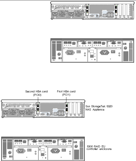
The Sun StorageTek 5320 NAS Appliance connects to each controller enclosure with a pair of optical fiber cables. Optical SFP transceivers have been installed in the controller host channel ports to interface with the optical fiber cable's LC connectors. Refer to FIGURE 3-1 for port locations.
|
Note - HBA cards are inserted only in the far left on the low-profile riser assembly of the Sun StorageTek 5320 NAS Appliance. |
This section contains details on the following:
Use the instructions in this section if you are connecting one controller enclosure to the Sun StorageTek 5320 NAS Appliance.
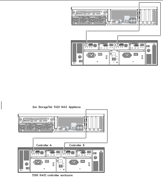
For a Sun StorageTek 5320 NAS Appliance with one dual port HBA card (FIGURE 3-2):
1. Connect the HBA port 2 on the Sun StorageTek 5320 NAS Appliance to the Controller A host 1 port.
2. Connect the HBA port 1 on the Sun StorageTek 5320 NAS Appliance to the Controller B host 1 port.
|
Note - The host 2 port on the controller A and controller B remain empty. |
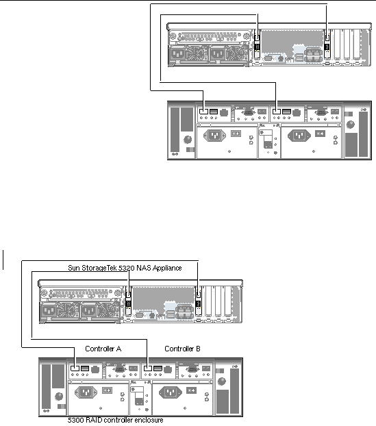
For a Sun StorageTek 5320 NAS Appliance with two dual port HBA cards (FIGURE 3-3):
1. Connect the HBA port 1 of the first HBA card to the Controller A host 1 port.
2. Connect the HBA port 1 of the second HBA card to the Controller B host 1 port.
|
Note - The host 2 port on the controller A and controller B remain empty. |
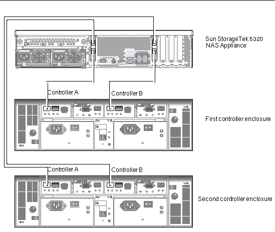
Use the instructions in this section and refer to FIGURE 3-4 if you are connecting two controller enclosures to the Sun StorageTek 5320 NAS Appliance.
|
Note - The Sun StorageTek 5320 NAS Appliance must have two HBA cards to connect to two controller enclosures. |
1. Connect the HBA port 1 of the first HBA card to the Controller A host 1 port on the second controller enclosure.
2. Connect the HBA port 1 of the second HBA card to the Controller B host 1 port on the second controller enclosure.
3. Connect the HBA port 2 of the first HBA card to the Controller A host 1 port on the first controller enclosure.
4. Connect the HBA port 2 of the second HBA card to the Controller B host 1 port on the first controller enclosure.
A controller enclosure uses Controller A and Controller B expansion ports to connect to FC-AL ports at the back of an expansion enclosure (FIGURE 3-5).
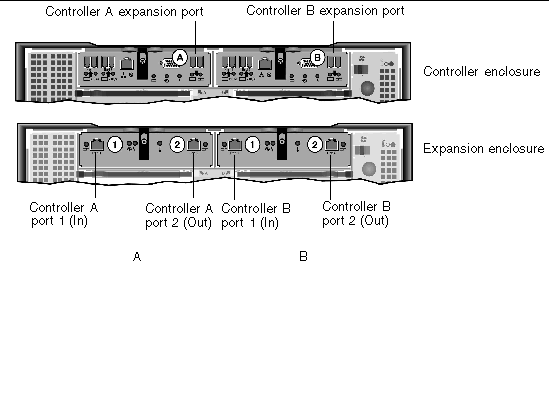
The controller enclosures and the expansion enclosures connect with a pair of Active Copper cables. These copper cables have transceiver electronics built into their connector ends. They plug directly into the SFP ports of the controllers and expansion enclosures.
|
Note - A maximum of seven EU F or eight EU S expansion enclosures can be attached to a controller enclosure. |
The cabling differs depending on the number of expansion enclosures you are connecting:
To connect a controller enclosure and one expansion enclosure, two 2-meter Active Copper cables are required. Refer to FIGURE 3-6.
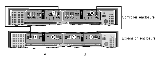
1. Connect one Active Copper cable between the A side expansion port of the controller enclosure and the A side port 1 of the expansion enclosure.
2. Connect one Active Copper cable between the B side expansion port of the controller enclosure and the B side port 2 of the expansion enclosure.
|
Note - The A side port 2 and B side port 1 of the expansion enclosure remain empty. |
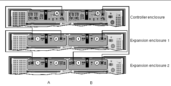
To connect a controller enclosure and two expansion enclosures, four 2-meter Active Copper cables are required. Refer to FIGURE 3-7.

|
Caution - Do not mix EU F (Fibre Channel) and EU S (SATA) expansion enclosures attached to a controller enclosure. |
1. Connect one Active Copper cable between the A side expansion port of the controller enclosure and the A side port 1 of expansion enclosure 1.
2. Connect one Active Copper cable between the A side port 2 of expansion enclosure 1 and the A side port 1 of expansion enclosure 2.
3. Connect one Active Copper cable between the B side expansion port of the controller enclosure and the B side port 2 of expansion enclosure 2.
4. Connect one Active Copper cable between the B side port 1 of expansion enclosure 2 and the B side port 2 of expansion enclosure 1.
|
Note - The A side port 2 of expansion enclosure 2 and the B side port 1 of expansion enclosure 1 remain empty. |
|
|
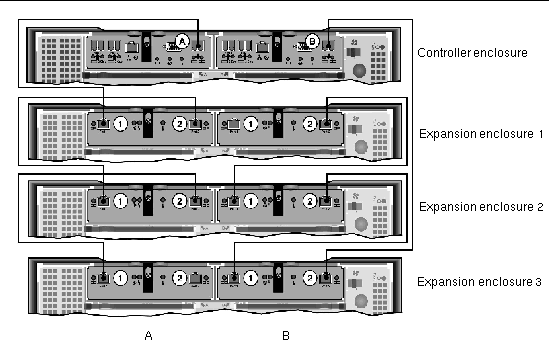
To connect a controller enclosure and three expansion enclosures, six 2-meter Active Copper cables are required. Refer to FIGURE 3-8.

|
Caution - Do not mix EU F (Fibre Channel) and EU S (SATA) expansion enclosures attached to a controller enclosure. |
1. Connect one Active Copper cable between the A side expansion port of the controller enclosure and the A side port 1 of expansion enclosure 1.
2. Connect one Active Copper cable between the A side port 2 of expansion enclosure 1 and the A side port 1 of expansion enclosure 2.
3. Connect one Active Copper cable between the A side port 2 of expansion enclosure 2 and the A side port 1 of expansion enclosure 3.
4. Connect one Active Copper cable between the B side expansion port of the controller enclosure and B side port 2 of expansion enclosure 3.
5. Connect one Active Copper cable between the B side port 1 of expansion enclosure 3 and the B side port 2 of expansion enclosure 2.
6. Connect one Active Copper cable between the B side port 1 of expansion enclosure 2 and the B side port 2 of expansion enclosure 1.
|
Note - The A side port 2 of expansion enclosure 3 and the B side port 1 of expansion enclosure 1 remain empty. |
|
|
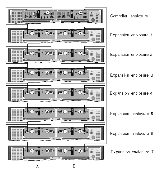
To connect a controller enclosure and seven expansion enclosures, fourteen 2-meter Active Copper cables are required. Refer to FIGURE 3-9.

|
Caution - Do not mix EU F (Fibre Channel) and EU S (SATA) expansion enclosures attached to a controller enclosure. |
1. Connect one Active Copper cable between the A side expansion port of the controller enclosure and the A side port 1 of expansion enclosure 1.
2. Connect one Active Copper cable between the A side port 2 of expansion enclosure 1 and the A side port 1 of expansion enclosure 2.
3. Continue to connect one Active Copper cable between the A side port 2 of each expansion enclosure and the A side port 1 of the expansion enclosure directly below it, until the A sides of all expansion enclosures are interconnected with Active Copper cables.
4. Connect one Active Copper cable between the B side expansion port of the controller enclosure and the B side port 2 of expansion enclosure 7.
5. Connect one Active Copper cable between the B side port 1 of expansion enclosure 7 and the B side port 2 of expansion enclosure 6.
6. Continue to connect one Active Copper cable between the B side port 1 of each expansion enclosure and the B side port 2 of the expansion enclosure directly above it, until the B sides of all expansion enclosures are interconnected with Active Copper cables.
|
Note - The A side port 2 of expansion enclosure 7 and the B side port 1 of expansion enclosure 1 remain empty. |
Use the following procedures to connect the Sun StorageTek 5320 NAS Appliance to the network. The available network connectors depend on your system configuration: Fast Ethernet or optical Gigabit Ethernet. Each configuration is described in the following sections.
|
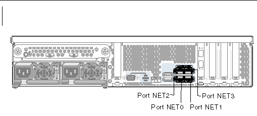
Refer to FIGURE 3-10 for NIC port locations.
1. To connect the Sun StorageTek 5320 NAS Appliance to a 100BASE-T Fast Ethernet network or to a 1000BASE-T Gigabit Ethernet network, connect an RJ-45 unshielded twisted-pair cable from your local area network (LAN) to port NET0 on the back of the Sun StorageTek 5320 NAS Appliance.
2. For additional LAN connections, continue to connect in order: NET1, NET2, and NET3.
|
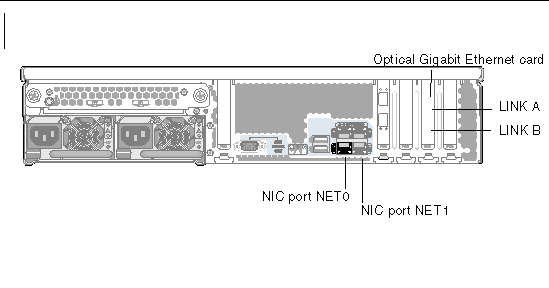
Refer to FIGURE 3-11 for NIC and optical Gigabit Ethernet port locations.
To connect the Sun StorageTek 5320 NAS Appliance to an optical Gigabit Ethernet network, you must have the optional add-in optical Gigabit Ethernet connections.
 Connect an FC cable from the network to the top (LINK A) and connect another FC cable from the network to the bottom (LINK B) optical Gigabit Ethernet connector on the back of the Sun StorageTek 5320 NAS Appliance.
|
Note - Later, when you configure the system (see Initial Sun StorageTek 5320 NAS Appliance Configuration), the LINK A port displays as "Port emf3" and the LINK B port displays as "Port emf4." The NET0 port displays as "Port emc1" and the NET1 port displays as "Port emc2." |
|
Note - If you are using a UPS, connect all units to the UPS. |
|
Note - To achieve fault tolerance, units with two power supplies should receive power from two different AC circuits. |
|
1. Verify that all cables between the Sun StorageTek 5320 NAS Appliance, controller enclosures, and expansion enclosures are properly secured according to the instructions in Connecting the Sun StorageTek 5320 NAS Appliance to Controller Enclosures and Connecting Controller Enclosures to Expansion Enclosures.
2. Power on each expansion enclosure by setting the two power supply switches to the On position.
3. Check that all LEDs on the expansion enclosure front panels turn solid green to indicate good operation.
4. Power on each controller enclosure by setting the two power supply switches to the On position.
5. Check that all LEDs on the controller enclosure front panels turn solid green to indicate good operation.
6. Verify that the Sun StorageTek 5320 NAS Appliance is connected to the network.
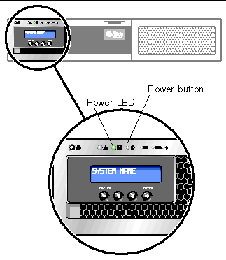
7. Using a pen tip or similar implement, press the recessed Power button (FIGURE 3-12).
|
Note - These instructions apply to the Sun StorageTek 5320 NAS Appliance only. For cluster configuration instructions, refer to Chapter 4. For NAS Gateway System or NAS Gateway Cluster System configuration instructions, refer to Chapter 5. |
To complete the initial Sun StorageTek 5320 NAS Appliance configuration, you must do the following:
To configure the Sun StorageTek 5320 NAS Appliance, you must have an IP address for the system. You can assign an IP address in one of two ways:
To dynamically acquire an IP address through a DHCP server, you must either have an existing DHCP server on the network or have a DHCP relay agent on the network with an accessible DHCP server on another network. If a DHCP server is not available, you must input the IP address through the LCD panel on the front panel of the Sun StorageTek 5320 NAS Appliance.
If your system supports DHCP, the DHCP server automatically assigns an IP address when the Sun StorageTek 5320 NAS Appliance boots for the first time.
If a DHCP server is not available, you must configure the IP address using the LCD panel.
1. Turn on the Sun StorageTek 5320 NAS Appliance and wait for the boot sequence to complete. The LCD panel displays the following:
A: Set Static IP
B: Retry DHCP
2. Press the ENTER button once, and then select A. Network Config.
3. Select A to set Gateway, if needed.
4. Select B to set the port-emc1 that corresponds to NIC port NET0.
5. Enter the following values in the order listed:
To enter data, use the up and down arrow buttons to change digits and press the ENTER button to confirm each digit. The cursor moves to the next digit. Once the last digit is set, press the ENTER button again to proceed to the next network setting. After the broadcast address is set, press the ENTER button to return to the Network Config menu.
When you connect to the Web Administrator for the first time, the Configuration Wizard launches automatically.
1. From a client on the same network, open a web browser and type the IP address of the Sun StorageTek 5320 NAS Appliance in the address or location field, for example:
The Web Administrator GUI for the Sun StorageTek 5320 NAS Appliance appears in your browser with a login screen.
|
Note - After you reach the login screen, you might want to bookmark it or add it to your Favorites list so that you do not have to remember the IP address in the future. |
2. On the Web Admin login screen, click Apply.
The password can be set later. Refer to the Sun StorageTek 5320 NAS Appliance and Gateway System Administration Guide.
3. On the System Operations, Set Time and Date panel, select the date, the time, and the time zone, and click Apply. Then click Yes to confirm.
This sets the secure clock to the same time and date. Make sure you set the time and date accurately as you can set the secure clock only once.
4. Accept the license agreement to start the Configuration wizard.
If you decline, Web Administrator returns you to the main login screen.
5. Follow the on-screen prompts, entering information as requested.
For more detailed descriptions of the wizard screens, refer to the Sun StorageTek 5320 NAS Appliance and Gateway System Administration Guide.
6. If your system uses DHCP to assign DNS, WINS, or IP and gateway addresses, these fields are automatically configured. When you reach these screens in the wizard, verify the information, and then continue with the wizard.
|
Note - When adding your DNS server, click Add to ensure the DNS server has been added. |
7. On the Confirmation screen, review the configuration information you have added.
|
Note - Be sure the configuration information is accurate before continuing. |
8. Click Finish on the wizard Confirmation screen.
The system configures the settings and indicates that in the Save Configuration screen.
9. Click Close on the Save Configuration screen.
10. Use Web Admin to configure file systems.
Refer to the Sun StorageTek 5320 NAS Appliance and Gateway System Administration Guide for information on creating file systems.
Copyright © 2006, Sun Microsystems, Inc. All Rights Reserved.