This appendix gives the pinouts for the server rear ports and identifies connectors on various server boards. Topics include:
A.1 Gigabit Ethernet Ports
The server has four autonegotiating 10/100/1000BASE-T Gigabit Ethernet system domain ports. All four Ethernet ports use a standard RJ-45 connector, the transfer rates for which are given in TABLE A-1. FIGURE A-1 shows the pin numbering of the ports. TABLE A-2 describes the pin signals.
TABLE A-1 Ethernet Connection Transfer Rates
|
Connection Type
|
IEEE Terminology
|
Transfer Rate
|
|
Ethernet
|
10BASE-T
|
10 Mbps
|
|
Fast Ethernet
|
100BASE-TX
|
100 Mbps
|
|
Gigabit Ethernet
|
1000BASE-T
|
1000 Mbps
|
FIGURE A-1 Gigabit Ethernet Port Pin Numbering
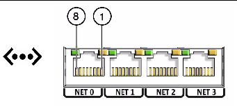
TABLE A-2 Gigabit Ethernet Port Signals
|
Pin
|
Signal Description
|
Pin
|
Signal Description
|
|
1
|
Transmit/Receive Data 0 +
|
5
|
Transmit/Receive Data 2 -
|
|
2
|
Transmit/Receive Data 0 -
|
6
|
Transmit/Receive Data 1 -
|
|
3
|
Transmit/Receive Data 1 +
|
7
|
Transmit/Receive Data 3 +
|
|
4
|
Transmit/Receive Data 2 +
|
8
|
Transmit/Receive Data 3 -
|
A.2 Network Management Port
The server has one 10BASE-T Ethernet management domain interface, labeled NET MGT. For information on configuring this port for managing the server with ILOM, refer to the Sun Integrated Lights Out Manager 2.0 User’s Guide.

|
Caution - If you are planning to use the network management (NET MGT) port, you must use a shielded Ethernet cable to maintain your server’s NEBS compliance. The cable’s shield must be grounded at both ends.
|
FIGURE A-2 Network Management Port Pin Numbering

TABLE A-3 Network Management Connector Signals
|
Pin
|
Signal Description
|
Pin
|
Signal Description
|
|
1
|
Transmit Data +
|
5
|
Common Mode Termination
|
|
2
|
Transmit Data -
|
6
|
Receive Data -
|
|
3
|
Receive Data +
|
7
|
Common Mode Termination
|
|
4
|
Common Mode Termination
|
8
|
Common Mode Termination
|
A.3 Serial Port
The server has one serial port, labeled SER MGT. TABLE A-4 lists the default serial connection settings for the serial port.
TABLE A-4 Default Serial Connection Settings
|
Parameter
|
Setting
|
|
Connector
|
SERIAL MGT or l0l0l
|
|
Rate
|
9600 baud
|
|
Parity
|
None
|
|
Stop bits
|
1
|
|
Data bits
|
8
|
A.3.1 Serial Management Port
The serial management connector (labeled SER MGT) is an RJ-45 connector that can be accessed from the rear panel. This port is the default connection to the server. Use this port only for server management.

|
Caution - You must use a shielded twisted-pair (STP) Ethernet cable to maintain your server’s NEBS compliance. The cable’s shield must be grounded at both ends.
|
FIGURE A-3 shows the pin numbering of the serial management port. TABLE A-5 describes the pin signals.
FIGURE A-3 Serial Management Port Pin Numbering
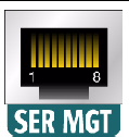
TABLE A-5 Serial Management RJ-45 Connector Signals
|
Pin
|
Signal Description
|
Pin
|
Signal Description
|
|
1
|
Request to Send
|
5
|
Ground
|
|
2
|
Data Terminal Ready
|
6
|
Receive Data
|
|
3
|
Transmit Data
|
7
|
Data Set Ready
|
|
4
|
Ground
|
8
|
Clear to Send
|
If you need to connect to the SERIAL MGT port using a cable with either a DB-9 or a DB-25 connector, use a supplied adapter to perform the crossovers given for each connector. The supplied RJ-45 to DB-9 and RJ-45 to DB-25 adapters are wired as described in TABLE A-6 and TABLE A-7.
A.3.1.1 RJ-45 to DB-9 Adapter Crossovers
TABLE A-6 RJ-45 to DB-9 Adappter Crossovers
|
Serial Port (RJ-45 Connector)
|
DB-9 Adapter
|
|
Pin
|
Signal Description
|
Pin
|
Signal Description
|
|
1
|
RTS
|
8
|
CTS
|
|
2
|
DTR
|
6
|
DSR
|
|
3
|
TXD
|
2
|
RXD
|
|
4
|
Signal Ground
|
5
|
Signal Ground
|
|
5
|
Signal Ground
|
5
|
Signal Ground
|
|
6
|
RXD
|
3
|
TXD
|
|
7
|
DSR
|
4
|
DTR
|
|
8
|
CTS
|
7
|
RTS
|
A.3.1.2 RJ-45 to DB-25 Adapter Crossovers
TABLE A-7 RJ-45 to DB-25 Adapter Crossovers
|
Serial Port (RJ-45 Connector)
|
DB-25 Adapter
|
|
Pin
|
Signal Description
|
Pin
|
Signal Description
|
|
1
|
RTS
|
5
|
CTS
|
|
2
|
DTR
|
6
|
DSR
|
|
3
|
TXD
|
3
|
RXD
|
|
4
|
Signal Ground
|
7
|
Signal Ground
|
|
5
|
Signal Ground
|
7
|
Signal Ground
|
|
6
|
RXD
|
2
|
TXD
|
|
7
|
DSR
|
20
|
DTR
|
|
8
|
CTS
|
4
|
RTS
|
A.4 Video Connector
The video connector (VGA) is an HD-15 connector that can be accessed from the back panel.
FIGURE A-4 Video Connector Diagram
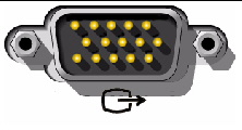
TABLE A-8 Video Connector Signals
|
Pin
|
Signal Description
|
Pin
|
Signal Description
|
|
1
|
Red Video
|
9
|
[KEY]
|
|
2
|
Green Video
|
10
|
Sync Ground
|
|
3
|
Blue Video
|
11
|
Monitor ID - Bit 1
|
|
4
|
Monitor ID - Bit 2
|
12
|
Monitor ID - Bit 0
|
|
5
|
Ground
|
13
|
Horizontal Sync
|
|
6
|
Red Ground
|
14
|
Vertical Sync
|
|
7
|
Green Ground
|
15
|
N/C (Reserved)
|
|
8
|
Blue Ground
|
|
|
A.5 Alarm Port
The alarm port on the rear panel uses a standard DB-15 connector. In a telecommunications environment, use this port to connect to the central office alarming system. FIGURE A-5 shows the pin numbering of the alarm port. TABLE A-9 describes the pin signals.
| Note - The alarm port relay contacts are rated for 100 V 0.2 A maximum.
|
FIGURE A-5 Alarm Port Pin Numbering
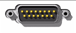
TABLE A-9 Alarm Connector Signals
|
Pin
|
Signal Description
|
Pin
|
Signal Description
|
|
1
|
RESET0+
|
9
|
ALARM1_NC
|
|
2
|
RESET0-
|
10
|
ALARM1_COM
|
|
3
|
RESET1+
|
11
|
ALARM2_NO
|
|
4
|
RESET1-
|
12
|
ALARM2_NC
|
|
5
|
ALARM0_NO
|
13
|
ALARM2_COM
|
|
6
|
ALARM0_NC
|
14
|
ALARM3_NO
|
|
7
|
ALARM0_COM
|
15
|
ALARM3_COM
|
|
8
|
ALARM1_NO
|
CHASSIS
|
FRAME GND
|
Each alarm has a corresponding alarm LED on the front panel:
- ALARM0 and the Critical LED
- ALARM1 and the Major LED
- ALARM2 and Minor LED
- ALARM3 and User LED
A.6 USB Ports
The server has four USB ports for attaching supported USB 2.0 compliant devices. USB ports 0 and 1 are on the rear panel and USB ports 2 and 3 are on the motherboard. FIGURE A-6 shows the pin numbering of the USB ports and TABLE A-10 describes the pin signals.
FIGURE A-6 USB Ports Pin Numbering

TABLE A-10 USB Connector Pin Signals
|
Pin
|
Signal Description
|
|
1
|
+5 V
|
|
2
|
DAT-
|
|
3
|
DAT+
|
|
4
|
Ground
|
| Sun Netra X4250 Server Service Manual
|
820-4056-11
|
   
|
Copyright © 2010, Oracle and/or its affiliates. All rights reserved.


