Part III Logical Design
A logical architecture identifies the components of a Directory Server Enterprise Edition deployment, and shows interrelationships between the components. Typically, use cases developed during the technical requirements phase indicate which components the deployment requires. However, the required components can often be derived directly from the business requirements.
This part provides sample logical architectures that are based on typical Directory Server Enterprise Edition deployment scenarios. The information in this part flows from a basic, single-server deployment to more complex deployments that span multiple data centers. The architectures discussed in the later chapters of this part build on the simpler architectures discussed in the earlier chapters.
This part includes the following chapters:
-
Chapter 9, Designing a Basic Deployment describes a basic Directory Server Enterprise Edition deployment.
-
Chapter 10, Designing a Scaled Deployment describes a deployment scaled to meet additional service requirements.
-
Chapter 11, Designing a Global Deployment covers deployment considerations for deployments across multiple data centers.
-
Chapter 12, Designing a Highly Available Deployment describes deployments designed to meet availability requirements.
Chapter 9 Designing a Basic Deployment
In the simplest Directory Server Enterprise Edition deployment, your directory service requirements can be fulfilled by a single Directory Server, installed on one machine, in a single data center. Such a scenario might occur in a small organization or if, you are running Directory Server for demonstration or evaluation purposes. Note that the technical requirements discussed in the previous chapters apply equally to all deployments.
This chapter describes a basic deployment, involving a single Directory Server. The chapter covers the following topics:
Basic Deployment Architecture
A basic Directory Server Enterprise Edition deployment includes the following elements:
-
Directory Server instance files
-
Directory Server daemon
-
dsadm and dsconf command-line utilities
-
Directory Service Control Center (DSCC), if GUI access is required
-
Console Agent, if DSCC is used
These elements can all be installed on a single machine. The following figure illustrates the high-level architecture of a basic Directory Server Enterprise Edition deployment.
Figure 9–1 Basic Directory Server Enterprise Edition Architecture on a Single Machine
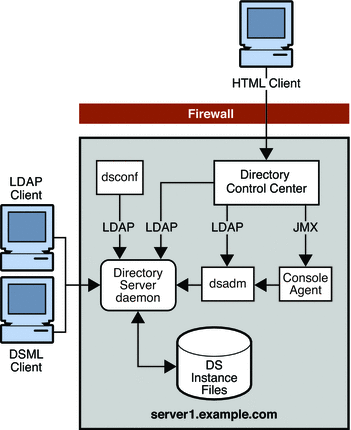
In this scenario, internal LDAP and DSML clients can be configured to access Directory Server directly. External HTML clients can be configured to access DSCC over a firewall.
Although all of the components described previously can be installed on a single machine, this is unlikely in a real deployment. A more typical scenario would be the installation of DSCC and the dsconf command-line utility on separate remote machines. All Directory Server hosts could then be configured remotely from these machines. The following figure illustrates this more typical scenario.
Figure 9–2 Basic Directory Server Enterprise Edition Architecture With Remote Directory Service Control Center
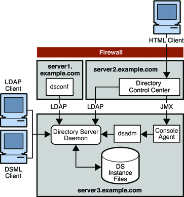
The Directory Server instance stores server and application configuration settings, as well as user information. Typically, server and application configuration information is stored in one suffix of Directory Server while user and group entries are stored in another suffix. A suffix refers to the name of the entry in the directory tree, below which data is stored.
Directory Service Control Center (DSCC) is a centralized, web-based user interface for all servers, and is the Directory component of Java Web Console. DSCC locates all servers and applications that are registered with it. DSCC displays the servers in a graphical user interface, where you can manage and configure the servers. The Directory Service Control Center might not be required in a small deployment because all functionality is also provided through a command-line interface.
In the chapters that follow, it is assumed that the Directory Service Control Center is installed on a separate machine. This aspect of the topology is not referred to again in the remaining chapters.
Basic Deployment Setup
Complete installation information is provided in the Sun Java System Directory Server Enterprise Edition 6.1 Installation Guide. The purpose of this section is to provide a clear picture of the elements that make up a basic deployment and how these elements work together.
This section lists the main tasks for setting up the basic deployment described in the previous section.
-
Install the required shared components, including the security packages.
-
Install Directory Server, the Console Agent, and the command-line interface.
-
If you want to manage the server by using the command-line utilities, do the following:
-
Create and start a standalone Directory Server instance by using the dsadm command.
-
Create and configure a suffix in the new instance, by using the dsconf command.
-
-
If you want to manage the server through a graphical user interface, do the following:
-
Initialize the Directory Service Control Center.
-
Create a Directory Server instance by using the Directory Service Control Center.
-
Create and configure a suffix in the new instance by using the Directory Service Control Center.
-
Improving Performance in a Basic Deployment
In even the most basic deployment, you might want to tune Directory Server to improve performance in specific areas. The following sections describe basic tuning strategies that can be applied to a simple single-server deployment. These strategies can be applied to each server in larger, more complex deployments, for improved performance across the topology.
Using Indexing to Speed Up Searches
Indexes speed up searches by effectively reducing the number of entries a search has to check to find a match. An index contains a list of values. Each value is associated with a list of entry identifiers. Directory Server can look up entries quickly by using the lists of entry identifiers in indexes. Without an index to manage a list of entries, Directory Server must check every entry in a suffix to find matches for a search.
-
Directory Server receives a search request from a client.
-
Directory Server examines the request to confirm that the search can be processed.
If Directory Server cannot perform the search, it returns an error to the client and might refer the search to another instance of Directory Server.
-
Directory Server determines whether it manages one or more indexes that are appropriate to the search.
-
If Directory Server manages indexes that are appropriate to the search, the server looks in all of the appropriate indexes for candidate entries. A candidate entry is an entry that might be a match for the search request.
-
If Directory Server does not manage an index appropriate to the search, the server generates the set of candidate entries by checking all of the entries in the database.
When Directory Server cannot use indexes, this process consumes more time and system resources.
-
-
Directory Server examines each candidate entry to determine whether the entry matches the search criteria.
-
Directory Server returns matching entries to the client application as it finds the entries.
Directory Server processes each search request as follows:
You can optimize search performance by doing the following:
-
Preventing Directory Server from performing searches on non-indexed entries
-
Ensuring that cache sizes are appropriately tuned
-
Limiting the length of an index
For a comprehensive overview of how indexes work, see Chapter 6, Directory Server Indexing, in Sun Java System Directory Server Enterprise Edition 6.1 Reference. For information about defining indexes, see Chapter 12, Directory Server Indexing, in Sun Java System Directory Server Enterprise Edition 6.1 Administration Guide.
Optimizing Cache for Search Performance
For improved search performance, cache as much directory data as possible in memory. By preventing the directory from reading information from disk, you limit the disk I/O bottleneck. Different possibilities exist for doing this, depending on the size of your directory tree, the amount of memory available, and the hardware used. Depending on the deployment, you might choose to allocate more or less memory to entry and database caches to optimize search performance. You might alternatively choose to distribute searches across Directory Server consumers on different servers.
Consider the following scenarios:
All Entries and Indexes Fit Into Memory
In the optimum case, the database cache and the entry cache fit into the physical memory available. The entry caches are large enough to hold all entries in the directory. The database cache is large enough to hold all indexes and entries. In this case, searches find everything in cache. Directory Server never has to go to file system cache or to disk to retrieve entries.
Ensure that database cache can contain all database indexes, even after updates and growth. When space runs out in the database cache for indexes, Directory Server must read indexes from disk for every search request, severely impacting throughput. You can monitor paging and cache activity with DSCC or through the command line.
Appropriate cache sizes must be determined through empirical testing with representative data. In general, the database cache size can be calculated as (total size of database files) x 1.2. Start by allocating a large amount of memory for the caches. Then exercise and monitor Directory Server to observe the result, repeating the process as necessary. Entry caches in particular might use much more memory than you allocate to these caches.
Sufficient Memory For 32-Bit Directory Server
Imagine a system with sufficient memory to hold all data in entry and database caches, but no support for a 64-bit Directory Server process. If hardware constraints prevent you from deploying Directory Server on a Solaris system with 64-bit support, size caches appropriately with respect to memory limitations for 32-bit processes. Then leave the remaining memory to the file system cache.
As a starting point when benchmarking performance, size the entry cache to hold as many entries as possible. Size the database cache relatively small such as 100 Mbytes without completely minimizing it, but letting file system cache hold the database pages.
Note –
File system cache is shared with other processes on the system, especially file-based operations. Thus, controlling file system cache is more difficult than controlling other caches, particularly on systems that are not dedicated to Directory Server.
The system might reallocate file system cache to other processes.
Avoid online import in this situation because import cache is associated with the Directory Server process.
Insufficient Memory
Imagine a system with insufficient memory to hold all data in entry and database caches. In this case, avoid causing combined entry and database cache sizes to exceed the available physical memory. This might result in heavy virtual memory paging that could bring the system to a virtual halt.
For small systems, start benchmarking by devoting available memory to entry cache and database caches, with sizes no less than 100 Mbytes each. Try disabling the file system cache by mounting Solaris UFS file systems with the -o forcedirectio option of the mount_ufs command. For more information, see the mount_ufs(1M) man page. Disabling file system cache can prevent the file system cache from using memory needed by Directory Server.
For large Directory Servers running on large machines, maximize the file system cache and reduce the database cache. Verify and correct assumptions through empirical testing.
Optimizing Cache for Write Performance
In addition to planning a deployment for write scalability from the outset, provide enough memory for the database cache to handle updates in memory. Also, minimize disk activity. You can monitor the effectiveness of the database cache by reading the hit ratio in the Directory Service Control Center.
After Directory Server has run for some time, the caches should contain enough entries and indexes that disk reads are no longer necessary. Updates should affect the database cache in memory, with data from the large database cache in memory being flushed only infrequently.
Flushing data to disk during a checkpoint can be a bottleneck. The larger the database cache size, the larger the bottleneck. Storing the database on a separate RAID system, such as a Sun StorEdgeTM disk array, can help improve update performance. You can use utilities such as iostat on Solaris systems to isolate potential I/O bottlenecks. For more information, see the iostat(1M) man page.
The following table shows database and log placement recommendations for systems with 2, 3, and 4 disks.
Table 9–1 Isolating Databases and Logs on Different Disks
Chapter 10 Designing a Scaled Deployment
The basic deployment described in Chapter 9, Designing a Basic Deployment assumes that a single Directory Server is enough to satisfy the read and write requirements of your organization. Organizations that have large read or write requirements, that is, several clients attempting to access directory data simultaneously, need to use a scaled deployment.
Generally, the number of searches a Directory Server instance can perform per second is directly related to the number and speed of the server's CPUs, provided there is sufficient memory to cache all data. Horizontal read scalability can be achieved by spreading the load across more than one server. This usually means providing additional copies of the data so that clients can read the data from more than one source.
Write operations do not scale horizontally because a write operation to a master server results in a write operation to every replica. The only way to scale write operations horizontally is to split the directory data among multiple databases and place those databases on different servers.
This chapter describes the different ways of scaling a Directory Server Enterprise Edition deployment to handle more reads and writes. The chapter covers the following topics:
Using Load Balancing for Read Scalability
Load balancing increases performance by spreading the read load across multiple servers. Load balancing can be achieved using replication, Directory Proxy Server, or a combination of the two.
Using Replication for Load Balancing
Replication is the mechanism that automatically copies directory data and changes from one directory server to another directory server. With replication, you can copy a directory tree or subtree that is stored in its own suffix between servers.
Note –
You cannot copy the configuration or monitoring information subtrees.
By replicating directory data across servers, you can reduce the access load on a single machine, improving server response time and providing read scalability. Replicating directory entries to a location close to your users also improves directory response time. Replication is generally not a solution for write scalability.
Basic Replication Concepts
The replication mechanism is described in detail in Chapter 4, Directory Server Replication, in Sun Java System Directory Server Enterprise Edition 6.1 Reference. The following section provides basic information that you need to understand before reviewing the sample topologies described later in this chapter.
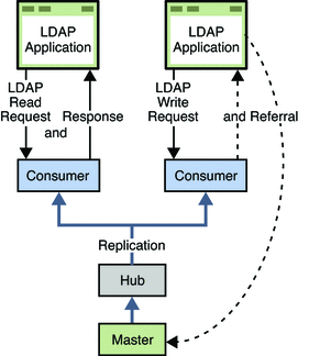
Master, Consumer, and Hub Replicas
A database that participates in replication is defined as a replica.
Directory Server distinguishes between three kinds of replicas:
-
Master or read-write replica. A read-write database that contains a master copy of the directory data. A master replica can process update requests from directory clients. A topology that contains more than one master is called a multi-master topology.
-
Consumer replica. A read-only database that contains a copy of the information in the master replica. A consumer replica can process search requests from directory clients but refers update requests to master replicas.
-
Hub replica. A read-only database (like a consumer replica) that is stored on a Directory Server that supplies one or more consumer replicas.
The following figure illustrates the role of each of these replicas in a replication topology.
Figure 10–1 Role of Replicas in a Replication Topology
Note –
The previous figure is for illustration purposes only and is not necessarily a recommended topology. Directory Server 6.1 supports an unlimited number of masters in a multi-master topology. A master-only topology is recommended in most cases.
Suppliers and Consumers
A Directory Server that replicates to other servers is called a supplier. A Directory Server that is updated by other servers is called a consumer. The supplier replays all updates on the consumer through specially designed LDAP v3 extended operations. In terms of performance, a supplier is therefore likely to be a demanding client application for the consumer.
A server can be both a supplier and a consumer, as in the following situations:
-
In multi-master replication, a master replica is mastered on two different Directory Servers. Each server acts as a supplier and a consumer of the other server.
-
When the server contains a hub replica, the server receives updates from a supplier and replicates the changes to consumers.
A server that plays the role of a consumer only is called a dedicated consumer.
For a master replica, the server must do the following:
-
Respond to update requests from directory clients
-
Maintain historical information and a change log
-
Initiate replication to consumers
The server that contains the master replica is responsible for recording any changes made to the master replica and for replicating these changes to consumers.
For a hub replica, the server must do the following:
-
Respond to read requests
-
Refer update requests to the servers that contain a master replica
-
Maintain historical information and a change log
-
Initiate replication to consumers
For a consumer replica, the server must do the following:
-
Respond to read requests
-
Maintain historical information
-
Refer update requests to the servers that contain a master replica
Multi-Master Replication
In a multi-master replication configuration, data can be updated simultaneously in different locations. Each master maintains a change log for its replica. The changes that occur on each master are replicated to the other servers.
Multi-master configurations have the following advantages:
-
Automatic write failover occurs when one master is inaccessible.
-
Updates can be made on a local master in a geographically distributed environment.
Multi-master replication uses a loose consistency replication model. This means that the same entries may be modified simultaneously on different servers. When updates are sent between the two servers, any conflicting changes must be resolved. Various attributes of a WAN, such as latency, can increase the chance of replication conflicts. Conflict resolution generally occurs automatically. A number of conflict rules determine which change takes precedence. In some cases conflicts must be resolved manually. For more information, see Solving Common Replication Conflicts in Sun Java System Directory Server Enterprise Edition 6.1 Administration Guide.
The number of masters that are supported in a multi-master topology is theoretically unlimited. The number of consumers and hubs is also theoretically unlimited. However, the number of consumers to which a single supplier can replicate depends on the capacity of the supplier server. You can use the SLAMD Distributed Load Generation Engine (SLAMD) to assess the capacity of the supplier server. For information about SLAMD, and to download the SLAMD software, see http://www.slamd.com.
Unit of Replication
The smallest unit of replication is the suffix. The replication mechanism requires one suffix to correspond to one database. You cannot replicate a suffix, or namespace, that is distributed over two or more databases using custom distribution logic. The unit of replication applies to both consumers and suppliers, which means that you cannot replicate two suffixes to a consumer that holds only one suffix.
Change Log
Every server that acts as a supplier maintains a change log. A change log is a record that describes the modifications that have occurred on a master replica. The supplier replays these modifications to its consumers. When an entry is modified, renamed, added, or deleted, a change record that describes the LDAP operation is recorded in the change log.
Replication Agreement
Directory Server uses replication agreements to define how replication occurs between two servers. A replication agreement describes replication between one supplier and one consumer.
A replication agreement identifies the following:
-
The suffix to replicate
-
The consumer server to which the data is pushed
-
The times during which replication can occur
-
The bind DN and credentials that the supplier must use to bind to the consumer
-
How the connection is secured, SSL or client authentication, for example
-
Information about the replication status for this particular agreement
-
Information about replication filtering
Replication Priority
In versions of Directory Server prior to Directory Server6.1, updates were replicated in chronological order. In this version of the product, updates can be prioritized for replication. Priority is a boolean feature, it is on or off. There are no levels of priority. In a queue of updates waiting to be replicated, updates with priority are replicated before updates without priority. In a queue of updates waiting to be replicated, updates with priority are replicated before updates without priority.
The priority rules are configured according to the following parameters:
-
The identity of the client
-
The type of update
-
The entry or subtree that was updated
-
The attributes changed by the update
For more information, see Prioritized Replication in Sun Java System Directory Server Enterprise Edition 6.1 Reference.
Assessing Initial Replication Requirements
A successful replicated directory service requires comprehensive testing and analysis in a production environment. However, the following basic calculation enables you to start designing a replicated topology. The sections that follow use the result of this calculation as the basis of the replicated topology design.
 To Determine Initial Replication Requirements
-
Estimate the maximum number of searches per second that are required at peak usage time.
This estimate can be called Total searches.
-
Test the number of searches per second that a single host can achieve.
This estimate can be called Searches per host. Note that this should be evaluated with replication enabled.
The number of searches that a host can achieve is affected by several variables. Among these are the size of the entries, the capacity of the host, and the speed of the network. A number of third party performance testing tools are available to assist you in conducting these tests. The SLAMD Distributed Load Generation Engine (SLAMD) is an open source Java application designed for stress testing and performance analysis of network-based applications. SLAMD can be used effectively to perform this part of the replication assessment. For information about SLAMD, and to download the SLAMD software, see http://www.slamd.com.
-
Calculate the number of hosts that are required.
Number of hosts = Total searches / Searches per host
Load Balancing With Multi-Master Replication in a Single Data Center
Replication can balance the load on Directory Server in the following ways:
-
By spreading search activities across several servers
-
By dedicating specific servers to specific tasks or applications
Generally, if the Number of hosts calculated in Assessing Initial Replication Requirements is about 16, or not significantly larger, your topology should include only master servers in a fully connected topology. Fully connected means that every master replicates to every other master in the topology.
Note –
The Number of hosts is approximate and depends on the hardware and other details of the deployment.
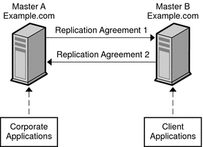
The following figure assumes that the Number of hosts is two. LDAP operations are divided between two master servers, based on the type of client application. This strategy reduces the load that is placed on each server and increases the total number of operations that can be served by the deployment.
Figure 10–2 Using Multi-Master Replication for Load Balancing
For a similar scenario in a global deployment, see Using Multi-Master Replication Over a WAN.
Load Balancing With Replication in Large Deployments
If your deployment requires a Number of hosts significantly larger than 16, you might need to add dedicated consumers to the topology.
The following figure assumes that the Number of hosts is 24 and, for simplicity, shows only a portion of the topology. (The remaining 10 servers would have an identical configuration, with a total of 8 masters and 16 consumers.
Figure 10–3 Using Multi-Master Replication for Load Balancing in a Large Deployment
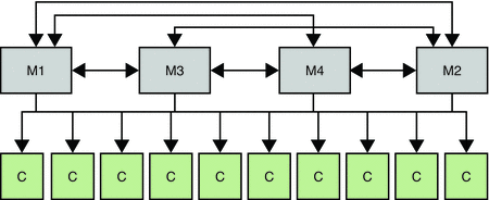
A change log can be enabled on any of these consumers if you need to do the following:
-
Promote the consumer to a master in the event of an outage
-
Perform a binary initialization from a master to any one of the consumers
If the Number of hosts is several hundred, you might want to add hubs to the topology. In such a case, there should be more hubs than masters, with up to 10 hubs for each master. Each hub should handle replication to only 20 consumers at most.
No topology should have the same number of hubs as masters, or the same number of hubs as consumers.
Using Server Groups to Simplify Multi-Master Topologies
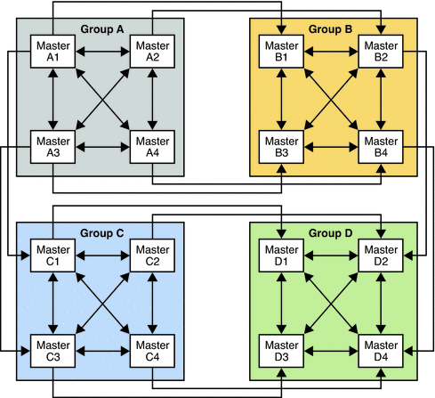
When the Number of hosts is large, the use of server groups can simplify the topology and improve resource usage. In a topology with 16 masters, the use of four server groups, each containing four masters, is easier to manage than 16 fully meshed masters.
Setting up a such a topology involves the following steps:
-
Configure the 16 masters, without any replication agreements.
-
Create four server groups and include four masters in each group.
-
Set up replication agreements between all the masters in a single group.
-
Set up replication agreements between the first master of each group, the second master of each group, and so forth.
The following figure shows the resulting topology.
Figure 10–4 Server Groups in Multi-Master Topologies
Using Directory Proxy Server for Load Balancing
Directory Proxy Server can use multiple servers to distribute the load of a single source of data. Directory Proxy Server can also ensure that if one of the servers is unavailable, the data remains available. Apart from distributing data, Directory Proxy Server provides operation-based load balancing. That is, the server is able to route client operations to a specific Directory Server, based on the type of operation.
Directory Proxy Server supports operation-based load balancing, and a variety of load balancing algorithms that determine how the workload is shared between Directory Servers. For a detailed description of each of these algorithms, see Chapter 16, Directory Proxy Server Load Balancing and Client Affinity, in Sun Java System Directory Server Enterprise Edition 6.1 Reference.
The following figure illustrates how the proportional algorithm is used to balance read load across two servers. Operation-based load balancing routes all writes to Master 1, unless that server fails. On failure all reads and writes are routed to Master 2.
Figure 10–5 Using Proportional and Operation-Based Load Balancing in a Scaled Deployment
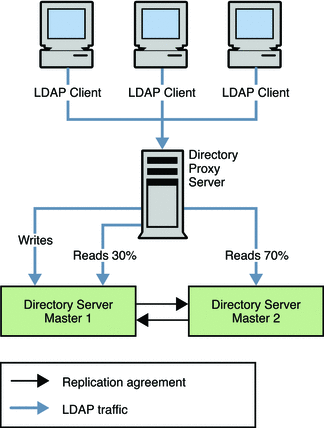
Note that the configuration for load balancing is not recalculated when one server instance fails. You cannot use proportional load balancing to create a “hot standby” server by setting a server's load balancing weight to 0.
Imagine, for example, you have three servers A, B, and C. Proportional load balancing has been configured such that servers A and B each receive 50% of the load. Server C is configured to have 0% of the load as it is designed to be a standby server only. If server A fails, 100% of the load will go to server B automatically. Only if server B also fails, will the load be distributed to server C. So, either the instance participates in load balancing all the time, always ready to take part of the load, or all primary instances have to fail before that server will take any load.
You can achieve something like a hot standby by using the saturation load balancing algorithm and applying a low weight to the standby server. Although the server is not a true standby server, you can configure the algorithm such that requests are distributed to this server only if the primary servers are under heavy load. Effectively if one primary server is disabled, the load on the other primary servers increases to the extent that requests must be distributed to the standby server.
Using Distribution for Write Scalability
Write operations are resource intensive. When a client requests a write operation, the follow sequence of events occurs on the database:
-
The backend database is locked
-
The entry is locked in the database cache
-
The access control check plug-in is called
-
Any backend pre-operation plug-ins are called
-
The database transaction begins
-
The database files are updated
-
The old entry cache is replaced with new data
-
The database transaction is committed
-
Any backend post-operation plug-ins are called
-
The backend database is unlocked
Because of this complex procedure, an increased number of writes can have a dramatic impact on performance.
As an enterprise grows, more client applications require rapid write access to the directory. Also, as more information is stored in a single Directory Server, the cost of adding or modifying entries in the directory database increases. This is because indexes become larger and it takes longer to manipulate the information that the indexes contain.
In some cases, the service level agreements might only be achieved by having all the data cached in memory. However, the data might be too large to fit on a single memory machine
When the volume of directory data increases to this extent, you need to break up the data so that it can be stored in multiple servers. One approach is to use a hierarchy to divide the information. By separating the information into multiple branches based on some criteria, each branch can be stored on a separate server. Each server can then be configured with chaining or referrals to enable clients to access all the information from a single point.
In this kind of division, each server is responsible for only a part of the directory tree. A distributed directory works in a similar way to the Domain Name Service (DNS). The DNS assigns each portion of the DNS namespace to a particular DNS server. In the same way, you can distribute your directory namespace across servers while maintaining, from a client standpoint, a single directory tree.
A hierarchy-based distribution mechanism has certain disadvantages. The main problem is that this mechanism requires that the clients know exactly where the information is. Alternatively, the clients must perform a broad search to find the data. Another problem is that some directory-enabled applications might not have the capability to deal with the information if it is broken up into multiple branches.
Directory Server supports hierarchy-based distribution in conjunction with the chaining and referral mechanisms. However, a distribution feature is also provided with Directory Proxy Server, which supports smart routing. This feature enables you to decide on the best distribution mechanism for your enterprise.
Using Multiple Databases
Directory Server stores data in high-performance, disk-based LDBM databases. Each database consists of a set of files that contains all of the data that is assigned to this set. You can store different portions of your directory tree in different databases. Imagine, for example, that your directory tree contains three subsuffixes, as shown in the following figure.
Figure 10–6 Directory Tree With Three Subsuffixes

The data of the three subsuffixes can be stored in three separate databases as shown in the following figure.
Figure 10–7 Three Subsuffixes Stored in Three Separate Databases

When you divide your directory tree among databases, the databases can be distributed across multiple servers. This strategy generally equates to several physical machines, which improves performance. The three databases in the preceding illustration can be stored on two servers as shown in the following figure.
Figure 10–8 Three Databases Stored on Two Separate Servers

When databases are distributed across multiple servers, the amount of work that each server needs to do is reduced. Thus, the directory can be made to scale to a much larger number of entries than would be possible with a single server. Because Directory Server supports dynamic addition of databases, you can add new databases as required, without making the entire directory unavailable.
Using Directory Proxy Server for Distribution
Directory Proxy Server divides directory information into multiple servers but does not require that the hierarchy of the data be altered. An important aspect of data distribution is the ability break up the data set in a logical manner. However, distribution logic that works well for one client application might not work as well for another client application.
For this reason, Directory Proxy Server enables you to specify how data is distributed and how directory requests should be routed. For example, LDAP operations can be routed to different directory servers based on the directory information tree (DIT) hierarchy. The operations can also be routed based on operation type or on a custom distribution algorithm.
Directory Proxy Server effectively hides the distribution details from the client application. From the clients' standpoint, a single directory addresses their directory queries. Client requests are distributed according to a particular distribution method. Different routing strategies can be associated with different portions of the DIT, as explained in the following sections.
Routing Based on the DIT
This strategy can be used to distribute directory entries based on the DIT structure. For example, entries in the subtree o=sales,dc=example,dc=com can be routed to Directory Server A, and entries in the subtree o=hr,dc=example,dc=com can be routed to Directory Server B.
Routing Based on a Custom Algorithm
In some cases, you might want to distribute entries across directory servers without using the DIT structure. Consider, for example, a service provider who stores entries that represent subscribers under ou=subscribers,dc=example,dc=com. As the number of subscribers grows, there might be a need to distribute them across servers based on the range of the subscriber ID. With a custom routing algorithm, subscriber entries with an ID in the range 1-10000 can be located in Directory Server A, and subscriber entries with an ID in the range 10001-infinity can be located in Directory Server B. If the data on server B grows too large, the distribution algorithm can be changed so that entries with an ID starting from 2000 can be located on a new server, Server C.
You can implement your own routing algorithm using the Directory Proxy Server DistributionAlgorithm interface.
Using Directory Proxy Server to Distribute Requests Based on Bind DN
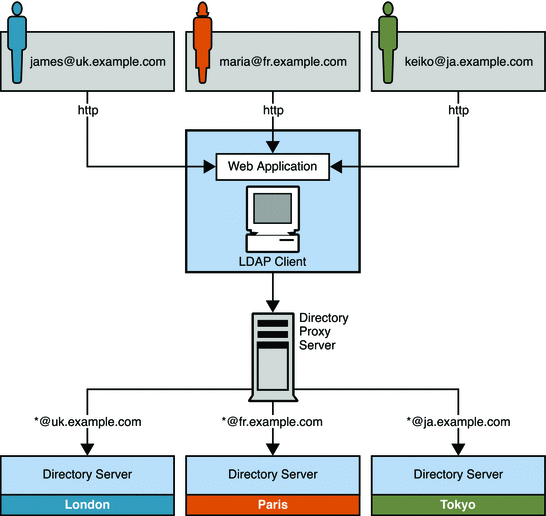
In this scenario, an enterprise distributes customer data between three master servers based on geographical location. Customers that are based in the United Kingdom have their data stored on a master server in London. French customers have their data stored on a master server in Paris. The data for Japanese customers is stored on a master server in Tokyo. Customers can update their own data through a single web-based interface.
Users can update their own information in the directory using a web-based application. During the authentication phase, users enter an email address. email addresses for customers in the UK take the form *@uk.example.com. For French customers, the email addresses take the form *@fr.example.com, and for Japanese customers, *@ja.example.com. Directory Proxy Server receives these requests through an LDAP-enabled client application. Directory Proxy Server then routes the requests to the appropriate master server based on the email address entered during authentication.
This scenario is illustrated in the following figure.
Figure 10–9 Using Directory Proxy Server to Route Requests Based on Bind DN
Distributing Data Lower Down in a DIT
In many cases, data distribution is not required at the top of the DIT. However, entries further up the tree might be required by the entries in the portion of the tree that has been distributed. This section provides a sample scenario that shows how to design a distribution strategy in this case.
Logical View of Distributed Data
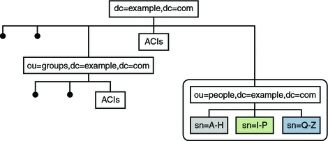
Example.com has one subtree for groups and a separate subtree for people. The number of group definitions is small and fairly static, while the number of person entries is large, and continues to grow. Example.com therefore requires only the people entries to be distributed across three servers. However, the group definitions, their ACIs, and the ACIs located at the top of the naming context are required to access all entries under the people subtree.
The following illustration provides a logical view of the data distribution requirements.
Figure 10–10 Logical View of Distributed Data
Physical View of Data Storage
The ou=people subtree is split across three servers, according to the first letter of the sn attribute for each entry. The naming context (dc=example,dc=com) and the ou=groups containers are stored in one database on each server. This database is accessible to entries under ou=people. The ou=people container is stored in its own database.
The following illustration shows how the data is stored on the individual Directory Servers.
Figure 10–11 Physical View of Data Storage
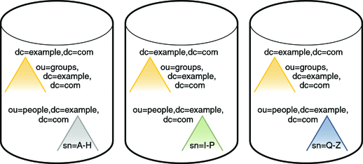
Note that the ou=people container is not a subsuffix of the top container.
Directory Server Configuration for Sample Distribution Scenario
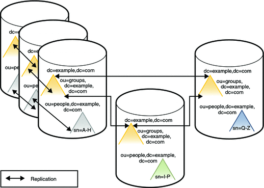
Each server described previously can be understood as a distribution chunk. The suffix that contains the naming context and the entries under ou=groups, is the same on each chunk. A multi-master replication agreement is therefore set up for this suffix across each of the three chunks.
For availability, each chunk is also replicated. At least two master replicas are therefore defined for each chunk.
The following illustration shows the Directory Server configuration with three replicas defined for each chunk. For simplification, the replication agreements are only shown for one chunk, although they are the same for the other two chunks.
Figure 10–12 Directory Server Configuration
Directory Proxy Server Configuration for Sample Distribution Scenario
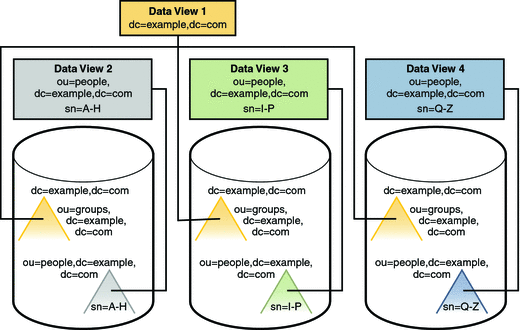
Client access to directory data through Directory Proxy Server is provided through data views. For information about data views see Chapter 17, Directory Proxy Server Distribution, in Sun Java System Directory Server Enterprise Edition 6.1 Reference.
For this scenario, one data view is required for each distributed suffix, and one data view is required for the naming context (dc=example,dc=com) and the ou=groups subtrees.
The following illustration shows the configuration of Directory Proxy Server data views to provide access to the distributed data.
Figure 10–13 Directory Proxy Server Configuration
Considerations for Data Growth
Distributed data is split according to a distribution algorithm. When you decide which distribution algorithm to use, bear in mind that the volume of data might change, and that your distribution strategy must be scalable. Do not use an algorithm that necessitates complete redistribution of data.
A numeric distribution algorithm based on uid, for example, can be scaled fairly easily. If you start with two data segments of uid=0-999 and uid=1000–1999, it is easy to add third segment of uid=2000–2999 at a later stage.
Using Referrals For Distribution
A referral is information returned by a server that tells a client application which server to contact to proceed with an operation request. If you do not use Directory Proxy Server to manage distribution logic, you must define the relationships between distributed data in another way. One way to define relationships is using referrals.
Directory Server supports three ways of configuring how and when referrals are returned:
-
Default referrals. The directory returns a default referral when a client application presents a DN for which the server does not have a matching suffix.
-
Suffix referrals. When an entire suffix has been taken offline for maintenance or security reasons, the server returns the referrals defined by that suffix. Read-only replicas of a suffix also return referrals to the master server when a client requests a write operation.
-
Smart referrals. These referrals are stored on entries within the directory. Smart referrals point to Directory Servers that have knowledge of the subtree whose DN matches the DN of the entry that contains the smart referral.
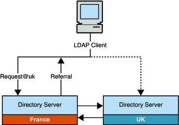
The following figure illustrates how referrals are used to direct clients from the UK to the appropriate server in a global topology. In this scenario, the client application must be able to connect to all the servers in the topology (at the TCP/IP level), to enable it to follow the referral.
Figure 10–14 Using Referrals to Direct Clients to a Specific Server
Using Directory Proxy Server With Referrals
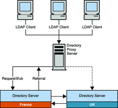
You can use Directory Proxy Server in conjunction with the referral mechanism to achieve the same result. The advantage of using Directory Proxy Server in this regard is that the load and complexity of client applications is reduced. Client applications are only aware of the Directory Proxy Server URL. If the distribution logic is changed, for any reason, this change is transparent to client applications.
The following figure illustrates how the scenario described previously can be simplified with the use of Directory Proxy Server. Client applications always connect to the Proxy Server, which handles the referrals itself.
Figure 10–15 Using Directory Proxy Server With Referrals
Chapter 11 Designing a Global Deployment
In a global deployment, access to directory services is required in more than one geographical location, or data center. This chapter provides strategies for effectively deploying Directory Server Enterprise Edition across multiple data centers. The strategies ensure that the quality of service requirements identified in Chapter 5, Defining Service Level Agreements are not compromised.
This chapter covers the following topics:
Using Replication Across Multiple Data Centers
One of the goals of replication is to enable geographic distribution of the LDAP service. Replication enables you to have identical copies of information on multiple servers and across more than one data center. Replication concepts are outlined in Chapter 10, Designing a Scaled Deployment in this guide, and described in detail in Chapter 4, Directory Server Replication, in Sun Java System Directory Server Enterprise Edition 6.1 Reference. This chapter focuses on the replication features that are used in a global deployment.
Using Multi-Master Replication Over a WAN
Directory Server supports multi-master replication over a WAN. This feature enables multi-master replication configurations across geographical boundaries in international, multiple data center deployments.
Generally, if the Number of hosts calculated in Assessing Initial Replication Requirements is less than 16, or not significantly larger, your topology should include only master servers in a fully connected topology, that is, every master replicates to every other master in the topology. In a multi-master replication over WAN configuration, all Directory Server instances separated by a WAN must not be running versions prior to Directory Server 5.2. For a multi-master topology with more than 4 masters, Directory Server 6.1 is required.
The replication protocol provides full asynchronous support, as well as window, grouping, and compression mechanisms. These features make multi-master replication over a WAN viable. Replication data transfer rates will always be less than what the available physical medium allows in terms of bandwidth. If the update volume between replicas cannot physically be made to fit into the available bandwidth, tuning will not prevent replicas from diverging under heavy update load. Replication delay and update performance are dependent on many factors, including but not limited to modification rate, entry size, server hardware, average latency and average bandwidth.
Internal parameters of the replication mechanism are optimized by default for WANs. However, if you experience slow replication due to the factors mentioned above, you may wish to empirically adjust the window size and group size parameters. You may also be able to schedule your replication to avoid peak network times, thus improving your overall network usage. Finally, Directory Server supports the compression of replication data to optimize bandwidth usage.
When you replicate data over a WAN link, some form of security to ensure data integrity and confidentiality is advised. For more information on security methods available in Directory Server, see Chapter 2, Directory Server Security, in Sun Java System Directory Server Enterprise Edition 6.1 Reference.
Group and Window Mechanisms
Directory Server provides group and window mechanisms to optimize replication flow. The group mechanism enables you to specify that changes are sent in groups, rather than individually. The group size represents the maximum number of data modifications that can be bundled into a single update message. If the network connection appears to be the bottleneck for replication, increase the group size and check replication performance again. For information on configuring the group size, see Configuring Group Size in Sun Java System Directory Server Enterprise Edition 6.1 Administration Guide.
The window mechanism specifies that a certain number of update requests are sent to the consumer, without the supplier having to wait for an acknowledgement from the consumer before continuing. The window size represents the maximum number of update messages that can be sent without immediate acknowledgement from the consumer. It is more efficient to send many messages in quick succession instead of waiting for an acknowledgement after each one. Using the appropriate window size, you can eliminate the time replicas spend waiting for replication updates or acknowledgements to arrive. If your consumer replica is lagging behind the supplier, increase the window size to a higher value than the default, such as 100, and check replication performance again before making further adjustments. When the replication update rate is high and the time between updates is therefore small, even replicas connected by a LAN can benefit from a higher window size. For information on configuring the window size, see Configuring Window Size in Sun Java System Directory Server Enterprise Edition 6.1 Administration Guide.
Both the group and window mechanisms are based on change size. Therefore, optimizing replication performance with these mechanisms might be impractical if the size of your changes varies considerably. If the size of your changes is relatively constant, you can use the group and window mechanisms to optimize incremental and total updates.
Replication Compression
In addition to the grouping and window mechanisms, you can configure replication compression on Solaris and Linux platforms. Replication compression streamlines replication flow, which substantially reduces the incidence of bottlenecks in replication over a WAN. Compression of replicated data can increase replication performance in specific cases, such as networks with sufficient CPU but low bandwidth, or when there are bulk changes to be replicated. You can also benefit from replication compression when initializing a remote replica with large entries. Do not set this parameter in a LAN (local area network) where there is wide network bandwidth, because the compression and decompression computations will slow down replication.
The replication mechanism uses the Zlib compression library. Empirically test and select the compression level that gives you best results in your WAN environment for your expected replication usage.
For more information on configuring replication compression, see Configuring Replication Compression in Sun Java System Directory Server Enterprise Edition 6.1 Administration Guide.
Using Fractional Replication
A global topology (with data centers in different countries) might require restricting replication for security or compliance reasons. For example, legal restrictions might state that specific employee information cannot be copied outside of the U.S.A. Or, a site in Australia might require Australian employee details only.
The fractional replication feature enables only a subset of the attributes that are present in an entry to be replicated. Attribute lists are used to determine which attributes can and cannot be replicated. Fractional replication can only be applied to read-only consumers.
For detailed information about how fractional replication works, see Fractional Replication in Sun Java System Directory Server Enterprise Edition 6.1 Reference. For information about how to configure fractional replication, see Fractional Replication in Sun Java System Directory Server Enterprise Edition 6.1 Administration Guide.
Using Prioritized Replication
Prioritized replication can be used when there is a strong business requirement to have tighter consistency for replicated data on specific attributes. In previous versions of Directory Server, updates were replicated in the order in which they were received. With prioritized replication, you can specify that updates to certain attributes take precedence when they are replicated to other servers in the topology.
Prioritized replication provides the following benefits:
-
Improved security. Prioritized replication is used by default for account lockout. Imagine for example that an employee leaves your organization, and you lock the employee's account. To ensure that the employee cannot log in to a remote server to which the account lockout has not been replicated, account lockout changes are replicated before other changes are replicated.
-
Improved consistency. Directory Server replication is loosely consistent. With prioritized replication, you can assure stronger consistency for certain attributes that are considered important in your organization.
Sample Replication Strategy for an International Enterprise
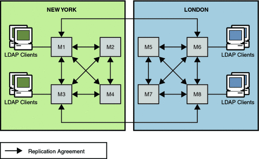
In this scenario, an enterprise has two major data centers, one in London and the other in New York, separated by a WAN. The scenario assumes that the network is very busy during normal business hours.
In this scenario, the Number of hosts has been calculated to be eight. A fully connected, 4-way multi-master topology is deployed in each of the two data centers. These two topologies are also fully connected to each other. For ease of comprehension, not all replication agreements between the two data centers are shown in the following diagram.
The replication strategy for this scenario includes the following:
-
Master copies of directory data are held on servers in both data centers.
-
A multi-master replication topology is deployed between the data centers to provide high availability and write-failover across the deployment.
-
Replication across the WAN link is scheduled so that it occurs only during off-peak hours to optimize bandwidth.
-
To increase performance, client applications are directed to local servers. Clients in the U.S. read from and write to masters in the New York data center. Clients in the UK read from and write to masters in the London data center.
Figure 11–1 Using Multi-Master Replication for Load Balancing in Two Data Centers
Using Directory Proxy Server in a Global Deployment
In a global enterprise, a centralized data model can cause scalability and performance issues. Directory Proxy Server can be used in such a situation to distribute data efficiently and to route search and update requests appropriately.
Sample Distribution Strategy for a Global Enterprise
In the architecture shown here, a large financial institution has its headquarters in London. The organization has data centers in London, New York, and Hong Kong. Currently, the vast majority of the data that is available to employees resides centrally in legacy RDBMS repositories in London. All access to this data from the financial institution’s client community is over the WAN.
The organization is experiencing scalability and performance problems with this centralized model and decides to move to a distributed data model. The organization also decides to deploy an LDAP directory infrastructure at the same time. Because the data in question is considered “mission critical” it must be deployed in a highly available, fault-tolerant infrastructure.
An analysis of client application profiles has revealed that the data is customer-based. Therefore, 95 percent of the data accessed by a geographical client community is specific to that community. Clients in Asia rarely access data for a customer in North America, although this does happen infrequently. The client community must also update customer information from time to time.
The following figure shows the logical architecture of the distributed solution.
Figure 11–2 Distributed Directory Infrastructure
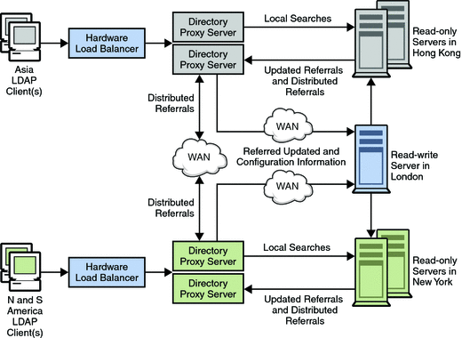
Given the profile of 95 percent local data access, the organization decides to distribute the directory infrastructure geographically. Multiple directory consumers are deployed in each geographical location: Hong Kong, New York, and London. London consumers are not shown in the diagram for ease of understanding. Each of these consumers is configured to hold the customer data specific to the location. Data for European and Middle East customers is held in the London consumers. Data for North and South American customers is held in the New York consumers. Data for Asian and Pacific Rim customers is held in the Hong Kong consumers.
With this deployment, the overwhelming data requirement of the local client community is located in the community. This strategy provides significant performance improvements over the centralized model. Client requests are processed locally, reducing network overhead. The local directory servers effectively partition the directory infrastructure, which provides increased directory server performance and scalability. Each set of consumer directory servers is configured to return referrals if a client submits an update request. Referrals are also returned if a client submits a search request for data that is located elsewhere.
Client LDAP requests are sent to Directory Proxy Server through a hardware load balancer. The hardware load balancer ensures that clients always have access to at least one Directory Proxy Server. The locally deployed Directory Proxy Server initially routes all requests to the array of local directory servers that hold the local customer data. The instances of Directory Proxy Server are configured to load balance across the array of directory servers. This load balancing provides automatic failover and failback.
Client search requests for local customer information are satisfied by a local directory. Appropriate responses are returned to the client through Directory Proxy Server. Client search requests for geographically “foreign” customer information are initially satisfied by the local directory server by returning a referral back to Directory Proxy Server.
This referral contains an LDAP URL that points to the appropriate geographically distributed Directory Proxy Server instance. The local Directory Proxy Server processes the referral on behalf of the local client. The local Directory Proxy Server then sends the search request to the appropriate distributed instance of Directory Proxy Server. The distributed Directory Proxy Server forwards the search request on to the distributed Directory Server and receives the appropriate response. This response is then returned to the local client through the distributed and the local instances of Directory Proxy Server.
Update requests received by the local Directory Proxy Server are also satisfied initially by a referral returned by the local Directory Server. Directory Proxy Server follows the referral on behalf of the local client. However, this time the proxy forwards the update request to the supplier directory server located in London. The supplier Directory Server applies the update to the supplier database and sends a response back to the local client through the local Directory Proxy Server. Subsequently, the supplier Directory Server propagates the update down to the appropriate consumer Directory Server.
Chapter 12 Designing a Highly Available Deployment
High availability implies an agreed minimum “up time” and level of performance for your directory service. Agreed service levels vary from organization to organization. Service levels might depend on factors such as the time of day systems are accessed, whether or not systems can be brought down for maintenance, and the cost of downtime to the organization. Failure, in this context, is defined as anything that prevents the directory service from providing this minimum level of service.
This chapter covers the following topics:
Availability and Single Points of Failure
Directory Server Enterprise Edition deployments that provide high availability can quickly recover from failures. With a high availability deployment, component failures might impact individual directory queries but should not result in complete system failure. A single point of failure (SPOF) is a system component which, upon failure, renders an entire system unavailable or unreliable. When you design a highly available deployment, you identify potential SPOFs and investigate how these SPOFs can be mitigated.
SPOFs can be divided into three categories:
-
Hardware failures, for example, server crashes, network failures, power failures, or disk drive crashes
-
Software failures, for example, Directory Server or Directory Proxy Server crashes
-
Database corruption
Mitigating SPOFs
You can ensure that failure of a single component does not cause an entire directory service to fail by using redundancy. Redundancy involves providing redundant software components, hardware components, or both. Examples of this strategy include deploying multiple, replicated instances of Directory Server on separate hosts, or using redundant arrays of independent disks (RAID) for storage of Directory Server databases. Redundancy with replicated Directory Servers is the most efficient way to achieve high availability.
You can also use clustering to provide a highly available service. Clustering involves providing pre-packaged high availability hardware and software. An example of this strategy is deploying Sun Cluster hardware and software.
Deciding Between Redundancy and Clustering
The remainder of this chapter describes in more detail the use of redundancy and clustering to ensure high availability. This section summarizes the advantages and disadvantages of each solution.
Advantages and Disadvantages of Redundancy
The more common approach to providing a highly available directory service is to use redundant server components and replication. Redundant solutions are usually less expensive and easier to implement than clustering solutions. These solutions are also generally easier to manage. Note that replication, as part of a redundant solution, has numerous functions other than availability. While the main advantage of replication is the ability to split the read load across multiple servers, this advantage causes additional overhead in terms of server management. Replication also offers scalability on read operations and, with proper design, scalability on write operations, within certain limits. For an overview of replication concepts, see Chapter 4, Directory Server Replication, in Sun Java System Directory Server Enterprise Edition 6.1 Reference.
During a failure, a redundant system might provide poorer availability than a clustering solution. Imagine, for example, an environment in which the load is shared between two redundant server components. The failure of one server component might put an excessive load on the other server, making this server respond more slowly to client requests. A slow response might be considered a failure for clients that rely on quick response times. In other words, the availability of the service, even though the service is operational, might not meet the availability requirements of the client.
Advantages and Disadvantages of Clustering
The main advantage of a clustered solution is automatic recovery from failure, that is, recovery without user intervention. Disadvantages of clustering are complexity and inability to recover from database corruption.
In a clustered environment, the cluster uses the same IP address for Directory Server and Directory Proxy Server, regardless of which cluster node is actually running the service. That is, the IP address is transparent to the client application. In a replicated environment, each machine in the topology has its own IP address. In this case, Directory Proxy Server can be used to provide a single point of access to the directory topology. The replication topology is therefore effectively hidden from client applications. To increase this transparency, Directory Proxy Server can be configured to follow referrals and search references automatically. Directory Proxy Server also provides load balancing and the ability to switch to another machine when one fails.
How Redundancy and Clustering Handle SPOFs
In terms of the SPOFs that are described at the beginning of this chapter, redundancy and clustering handle failure in the following ways:
-
Single hardware failure. In a clustered environment, this kind of failure has no impact on the directory service. Only multiple hardware failures impact the service in a cluster.
A single hardware failure is fatal to a machine that is not in a clustered environment. Therefore, even if you have redundant hardware, manual intervention is required to repair the failure.
-
Directory Server or Directory Proxy Server failure. In a clustered environment, the server is automatically restarted. Software failure must occur multiple times in quick succession to trigger the service group to switch to another node in the cluster. This handling of a software failure is also true in a redundant environment.
-
Database corruption. A cluster cannot survive this kind of failure. Depending on the architecture, a redundant solution should be able to survive database corruption.
Redundancy at the Hardware Level
This section provides basic information about hardware redundancy. Many publications provide comprehensive information about using hardware redundancy for high availability. In particular, see “Blueprints for High Availability” published by John Wiley & Sons, Inc.
Hardware SPOFs can be broadly categorized as follows:
-
Network failures
-
Failure of the physical servers on which Directory Server or Directory Proxy Server are running
-
Load balancer failures
-
Storage subsystem failures
-
Power supply failures
Failure at the network level can be mitigated by having redundant network components. When designing your deployment, consider having redundant components for the following:
-
Internet connection
-
Network interface card
-
Network cabling
-
Network switches
-
Gateways and routers
You can mitigate the load balancer as an SPOF by including a redundant load balancer in your architecture.
In the event of database corruption, you must have a database failover strategy to ensure availability. You can mitigate against SPOFs in the storage subsystem by using redundant server controllers. You can also use redundant cabling between controllers and storage subsystems, redundant storage subsystem controllers, or redundant arrays of independent disks.
If you have only one power supply, loss of this supply could make your entire service unavailable. To prevent this situation, consider providing redundant power supplies for hardware, where possible, and diversifying power sources. Additional methods of mitigating SPOFs in the power supply include using surge protectors, multiple power providers, and local battery backups, and generating power locally.
Failure of an entire data center can occur if, for example, a natural disaster strikes a particular geographic region. In this instance, a well-designed multiple data center replication topology can prevent an entire distributed directory service from becoming unavailable. For more information, see Using Replication and Redundancy for High Availability.
Redundancy at the Software Level
Failure in Directory Server or Directory Proxy Server can include the following:
-
Excessive response time
-
Write overload
-
Maximized file descriptors
-
Maximized file system
-
Poor storage configuration
-
Too many indexes
-
-
Read overload
-
Cache issues
-
CPU constraints
-
Replication issues
-
Synchronicity
-
Replication propagation delay
-
Replication flow
-
Replication overload
-
-
Large wildcard searches
These SPOFs can be mitigated by having redundant instances of Directory Server and Directory Proxy Server. Redundancy at the software level involves the use of replication. Replication ensures that the redundant servers remain synchronized, and that requests can be rerouted with no downtime. For more information, see Using Replication and Redundancy for High Availability.
Using Replication and Redundancy for High Availability
Replication can be used to prevent the loss of a single server from causing your directory service to become unavailable. A reliable replication topology ensures that the most recent data is available to clients across data centers, even in the case of a server failure. At a minimum, your local directory tree needs to be replicated to at least one backup server. Some directory architects say that you should replicate three times per physical location for maximum data reliability. In deciding how much to use replication for fault tolerance, consider the quality of the hardware and networks used by your directory. Unreliable hardware requires more backup servers.
Do not use replication as a replacement for a regular data backup policy. For information about backing up directory data, see Designing Backup and Restore Policies and Chapter 8, Directory Server Backup and Restore, in Sun Java System Directory Server Enterprise Edition 6.1 Administration Guide.
LDAP client applications are usually configured to search one LDAP server only. Custom client applications can be written to rotate through LDAP servers that are located at different DNS host names. Otherwise, LDAP client applications can only be configured to look at a single DNS host name for Directory Server. You can use Directory Proxy Server, DNS round robins, or network sorts to provide failover to backup Directory Servers. For information about setting up and using DNS round robins or network sorts, see your DNS documentation. For information about how Directory Proxy Server is used in this context, see Using Directory Proxy Server as Part of a Redundant Solution.
To maintain the ability to read data in the directory, a suitable load balancing strategy must be put in place. Both software and hardware load balancing solutions exist to distribute read load across multiple replicas. Each of these solutions can also determine the state of each replica and to manage its participation in the load balancing topology. The solutions might vary in terms of completeness and accuracy.
To maintain write failover over geographically distributed sites, you can use multiple data center replication over WAN. This entails setting up at least two master servers in each data center, and configuring the servers to be fully meshed over the WAN. This strategy prevents loss of service if any of the masters in the topology fail. Write operations must be routed to an alternative server if a writable server becomes unavailable. Various methods can be used to reroute write operations, including Directory Proxy Server.
The following sections describe how replication and redundancy are used to ensure high availability:
Using Redundant Replication Agreements
Redundant replication agreements enable rapid recovery in the event of failure. The ability to enable and disable replication agreements means that you can set up replication agreements that are used only if the original replication topology fails. Although this intervention is manual, the strategy is much less time consuming than waiting to set up the replication agreement when it is needed. The use of redundant replication agreements is explained and illustrated in Sample Topologies Using Redundancy for High Availability.
Promoting and Demoting Replicas
Promoting or demoting a replica changes its role in the replication topology. In a very large topology that contains dedicated consumers and hubs, online promotion and demotion of replicas can form part of a high availability strategy. Imagine, for example, a multi-master replication scenario, with two hubs configured for additional load balancing and failover. If one master goes offline, you can promote one of the hubs to a master to maintain optimal read-write availability. When the master replica comes back online, a simple demotion back to a hub replica returns you to the original topology.
For more information, see Promoting or Demoting Replicas in Sun Java System Directory Server Enterprise Edition 6.1 Administration Guide.
Using Directory Proxy Server as Part of a Redundant Solution
Directory Proxy Server is designed to support high availability directory deployments. The proxy provides automatic load balancing as well as automatic failover and fail back among a set of replicated Directory Servers. Should one or more Directory Servers in the topology become unavailable, the load is proportionally redistributed among the remaining servers.
Directory Proxy Server actively monitors the Directory Servers to ensure that the servers are still online. The proxy also examines the status of each operation that is performed. Servers might not all be equivalent in throughput and performance. If a primary server becomes unavailable, traffic that is temporarily redirected to a secondary server is directed back to the primary server as soon as the primary server becomes available.
Note that when data is distributed, multiple disconnected replication topologies must be managed, which makes administration more complex. In addition, Directory Proxy Server relies heavily on the proxy authorization control to manage user authorization. A specific administrative user must be created on each Directory Server that is involved in the distribution. These administrative users must be granted proxy access control rights.
Using Application Isolation for High Availability
Directory Proxy Server can also be used to protect a replicated directory service from failure due to a faulty client application. To improve availability, a limited set of masters or replicas is assigned to each application.
Suppose a faulty application causes a server shutdown when the application performs a specific action. If the application fails over to each successive replica, a single problem with one application can result in failure of the entire replicated topology. To avoid such a scenario, you can restrict failover and load balancing of each application to a limited number of replicas. The potential failure is then limited to this set of replicas, and the impact of the failure on other applications is reduced.
Sample Topologies Using Redundancy for High Availability
The following sample topologies show how redundancy is used to provide continued service in the event of failure.
Using Replication for Availability in a Single Data Center
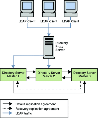
The data center that is illustrated in the following figure has a multi-master topology with three masters. In this scenario, the third master is used only for availability in thdse event of failure. Read and write operations are routed to Masters 1 and 2 by Directory Proxy Server, unless a problem occurs. To speed up recovery and to minimize the number of replication agreements, recovery replication agreements are created. These agreements are disabled by default but can be enabled rapidly in the event of a failure.
Figure 12–1 Multi-Master Replication in a Single Data Center
Single Data Center Failure Matrix
In the scenario depicted in Figure 12–1, various components might become unavailable. These potential points of failure and the related recovery actions are described in this table.
Table 12–1 Single Data Center Failure Matrix|
Failed Component |
Action |
|---|---|
|
Master 1 |
Read and write operations are rerouted to Masters 2 and 3 through Directory Proxy Server while Master 1 is repaired. The recovery replication agreement between Master 2 and Master 3 is enabled so that updates to Master 3 are replicated to Master 2. |
|
Master 2 |
Read and write operations are rerouted to Masters 1 and 3 while Master 2 is repaired. The recovery replication agreement between Master 1 and Master 3 is enabled so that updates to Master 3 are replicated to Master 1. |
|
Master 3 |
Because Master 3 is a backup server only, the directory service is not affected if this master fails. Master 3 can be taken offline and repaired without interruption to service. |
|
Directory Proxy Server |
Failure of Directory Proxy Server results in severe service interruption. A redundant instance of Directory Proxy Server is advisable in this topology. For an example of such a topology, see Using Multiple Directory Proxy Servers. |
Single Data Center Recovery Procedure
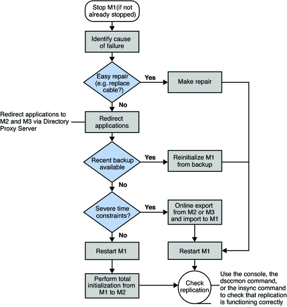
In a single data center with three masters, read and write capability is maintained if one master fails. This section describes a sample recovery strategy that can be applied to reinstate the failed component.
The following flowchart and procedure assume that one component, Master 1, has failed. If two masters fail simultaneously, read and write operations must be routed to the remaining master while the problems are fixed.
Figure 12–2 Single Data Center Sample Recovery Procedure
 To Recover on Failure of One Component
-
If Master 1 is not already stopped, stop it.
-
Identify the cause of the failure.
-
If the failure is easily repaired, by replacing a network cable, for example, make the repair and go to Step 3.
-
If the problem is more serious, the failure might take more time to fix.
-
Ensure that any applications that access Master 1 are redirected to point to Master 2 or Master 3, through Directory Proxy Server.
-
Check the availability of a recent backup.
-
If a recent backup is available, reinitialize Master 1 from the backup and go to Step 3.
-
If a recent backup is not available, do one of the following:
-
Restart Master 1 and perform a total initialization from Master 2 or from Master 3 to Master 1.
For details on this procedure, see Initializing Replicas in Sun Java System Directory Server Enterprise Edition 6.1 Administration Guide.
-
If performing a total initialization will take too long, perform an online export from Master 2, or Master 3, and an import to Master 1.
-
-
-
-
Start Master 1, if it is not already started.
-
If Master 1 is in read-only mode, set it to read/write mode.
-
Check that replication is functioning correctly.
You can use DSCC, dsccmon view-suffixes, or the insync command to check replication.
For more information, see Getting Replication Status in Sun Java System Directory Server Enterprise Edition 6.1 Administration Guide, dsccmon(1M), and insync(1).
Using Replication for Availability Across Two Data Centers
Generally in a deployment with two data centers, the same recovery strategy can be applied as described for a single data center. If one or more masters become unavailable, Directory Proxy Server automatically reroutes local reads and writes to the remaining masters.
As in the single data center scenario described previously, recovery replication agreements can be enabled. These agreements ensure that both data centers continue to receive replicated updates in the event of failure. This recovery strategy is illustrated in Figure 12–3.
An alternative to using recovery replication agreements is to use a fully meshed topology in which every master replicates its changes to every other master. While fewer replication agreements might be easier to manage, no technical reason exists for not using a fully meshed topology.
The only SPOF in this scenario would be the Directory Proxy Server in each data center. Redundant Directory Proxy Servers can be deployed to eliminate this problem, as shown in Figure 12–4.
Figure 12–3 Recovery Replication Agreements For Two Data Centers
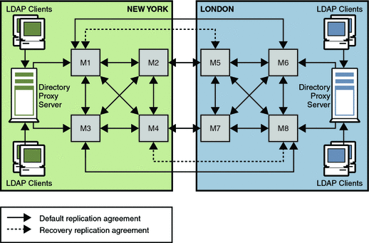
The recovery strategy depends on which combination of components fails. However, after you have a basic strategy in place to cope with multiple failures, you can apply that strategy if other components fail.
In the sample topology depicted in Figure 12–3, assume that Master 1 and Master 3 in the New York data center fail.
In this scenario, Directory Proxy Server automatically reroutes reads and writes in the New York data center to Master 2 and Master 4. This ensures that local read and write capability is maintained at the New York site.
Using Multiple Directory Proxy Servers
The deployment shown in the following figure includes an enterprise firewall that rejects outside access to internal LDAP services. Client LDAP requests that are initiated internally go through Directory Proxy Server by way of a network load balancer, ensuring high availability at the IP level. Direct access to the Directory Servers is prevented, except for the host that is running Directory Proxy Server. Two Directory Proxy Servers are deployed to prevent the proxy from becoming an SPOF.
A fully meshed multi-master topology ensures that all masters can be used at any time in the event of failure of any other master. For simplicity, not all replication agreements are shown in this diagram.
Figure 12–4 Internal High Availability Configuration
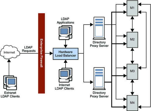
Using Application Isolation
In the scenario illustrated in the following figure a bug in Application 1 causes Directory Server to fail. The proxy configuration ensures that LDAP requests from Application 1 are only ever sent to Master 1 and to Master 3. When the bug occurs, Masters 1 and 3 fail. However, Applications 2, 3, and 4 are not disabled, because they can still reach a functioning Directory Server.
Figure 12–5 Using Application Isolation in a Scaled Deployment
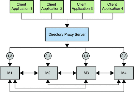
Using Clustering for High Availability
From a physical perspective, a cluster consists of between one and eight servers that work together as a single entity. The servers work together to provide highly available access to applications, system resources, and data. Each server can be a symmetric multiprocessor with multiple CPUs.
A clustering solution can provide high availability for the following:
-
Servers and software
-
Storage subsystem
-
Network adaptor
Clustering does not mitigate all SPOFs in a directory architecture. Failures in the external network, power generation, and data center must be mitigated outside of a clustering solution.
Currently the only supported clustering technology for Directory Server is Sun Cluster 3.1. Using Sun Cluster 3.1 for directory service availability involves installing and configuring the Sun Cluster HA for Directory Server data service as a failover data service. This strategy allows Directory Server to fail over safely in a Sun Cluster 3.1 environment.
The following figure shows the position of the Sun Cluster HA for Directory Server data service in the Sun Cluster 3.1 architecture.
Figure 12–6 Sun Cluster 3.1 Architecture
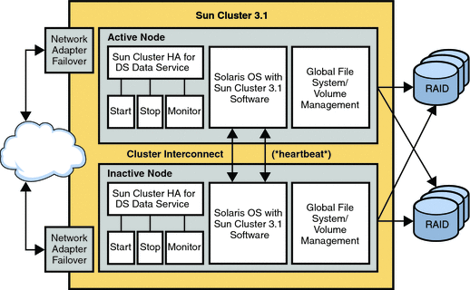
Hardware Redundancy
The architecture of a Sun Cluster hardware system is designed so that no SPOF can make a cluster unavailable. Redundant high-speed interconnects, storage system connections, and public networks ensure that cluster connectivity does not experience single failures.
Clients connect to the cluster through public network interfaces. If a network adapter card has multiple hardware interfaces, the card can connect to one or more public networks. You can set up nodes to include multiple network interface cards. The cards are configured so that one card is active, and the other cards operate as backups.
A cluster file system is a proxy between the kernel on one or more nodes and the underlying file system and volume manager. The cluster file system runs on a node that has a physical connection to the disks. For a cluster file system to be highly available, you must attach the disks to multiple nodes. A local file system that is made into a cluster file system is not highly available. A local file system implies a file system that is stored on a node's local disk.
A volume manager provides for mirrored or RAID 5 configurations for data redundancy of multihost disks. You can combine multihost disks with disk mirroring and striping to protect against both node failure and individual disk failure.
The cluster interconnect is a private network that transfers cluster-private communications and data service communications between cluster nodes. Redundant NICs, junctions, and cables protect against network failure.
Monitoring in a Clustered Solution
The cluster continuously monitors all its members. It blocks failed nodes from participating in the cluster, which prevents any exchange of corrupt data. The cluster also monitors applications, and it fails over or restarts the applications in case of failures.
Public Network Management, a subsystem of the Sun Cluster software, monitors the active interface. If the active adapter fails, Network Adapter Failover software is called to fail over the interface to one of the backup adapters.
The Cluster Membership Monitor (CMM) is a distributed set of agents, with one set per cluster member or node. The agents exchange messages over the cluster interconnect to ensure full connectivity among all nodes. When the CMM detects a change in cluster membership because of a node failure, for example, the CMM reconfigures the cluster. If the CMM detects a critical problem with a node, the CMM contacts the cluster framework. The cluster framework then forcibly shuts down the node and removes it from the cluster membership.
System Maintenance
You can minimize planned downtime for system maintenance by moving data and applications from the component that needs maintenance to another component on the system. When the maintenance is complete, you can move the data and applications back to the original component.
Directory Server Failover Data Service
The Directory Server Failover Data Service runs on a single node in a cluster. However, nodes can have multiple CPUs for scalability. A fault monitor periodically monitors this failover service.
The Resource Group Manager (RGM) manages data services as resources. When a CMM changes a cluster's membership, the RGM might request changes to the cluster's online or offline resources. The RGM starts and stops failover data services.
Disaster Recovery
The following sections describe how a service is recovered if the Directory Server Data Service fails and if the server fails.
Recovery in the Event of Application Failure
If the fault monitor determines that the Directory Server Data Service has failed, the monitor initiates action to restart the service. The action that is taken depends on the service's configuration.
You can configure the failover data service to attempt to restart a failed service on the same node. Alternatively, the data service can be configured to immediately start a failed service on a different node. If the data service is configured to attempt to restart on the same node, the fault monitor contacts the local RGM. The local RGM then attempts to restart the failed service. If this action fails, the local RGM attempts to start the service on a different node.
If a failed data service cannot be restarted on the same node, the local node's RGM attempts to locate a version of the service on another node. This action also occurs if the data service is configured to start on a different node after failure. If the local RGM finds a version of the service, the local RGM contacts the local CMM and requests that it contact the remote node over the cluster interconnect. The remote CMM then contacts the local RGM and directs it to start the service.
The following figure illustrates recovery in the event of application failure.
Figure 12–7 Application Failure and Recovery in a Sun Cluster 3.1 Architecture
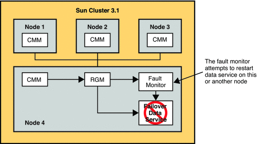
Recovery in the Event of Server Failure
If the server or node on which the Directory Server Data Service is running fails, the service is migrated to another working node. No user intervention is required. This service uses a failover resource group, a container that defines the Directory Server instances, and hosts that support the failover requirements.
The following figure illustrates recovery in the event of server failure.
Figure 12–8 Server Failure and Recovery in a Sun Cluster 3.1 Architecture
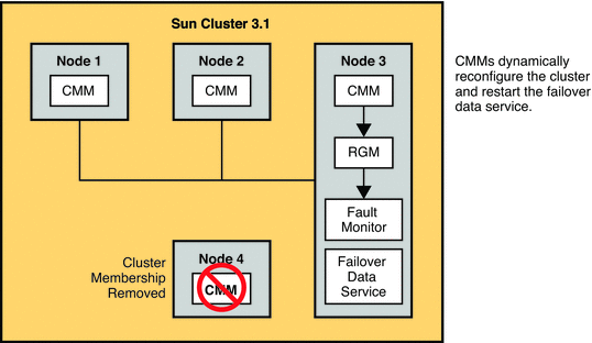
- © 2010, Oracle Corporation and/or its affiliates
