| Exit Print View | |
Sun Netra CP3270 ATCA Blade Server User’s Guide |

|
Documentation, Support, and Training
Evaluating Product Compatibility
Preparing to Install the Blade Server
Installing Components and Blade Server
Installing Optional Components
Software and Firmware Upgrades
Software and Firmware Upgrades
Administering Parameters and Configurations
Advanced Rear Transition Module Connectors (Zone 3)
Administering User Accounts and Security
The backplane has the following connectors, as shown in the following figure.

Figure Legend
1 Power connectors (Zone 1)
2 Data transport connectors (Zone 2)
3 Data transport connectors (Zone 2)
4 ARTM connectors (Zone 3)
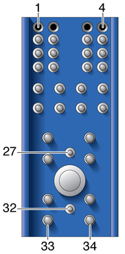
The blade server uses a 34-pin Positronic connector as the Zone 1 power distribution connector, as shown in the following figure. The J carrier is on the motherboard and the mating P carrier is on the midplane. Zone 1 provides the support for the following signals:
2 -48 VDC power feeds (four signals each; eight signals total)
2 IPMB ports (two signals each; four signals total)
Geographic address (eight signals)
2 ground pins
12 unpopulated pins

The analog test and ring voltage pins are left unconnected. The following table lists the pin assignments.
|
The data transport connectors support 40 signal pairs, providing 200 differential pairs for a PICMG 3.0 blade server to establish connectivity with up to 15 other blade servers through a common backplane. The J carrier is on the motherboard and the mating P carrier is on the midplane.
Front connectors are labeled J20 to J24, and backplane connectors are labeled P20 to P24, with both J20 and P20 being at the top of Zone 2. The front connector is a right angle connector and contains female contacts. The backplane contains male contacts.
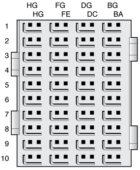
On the blade server, Zone 2 consists of two 120-pin HM-Zd connectors, labeled
J20 and J23, with 40 differential pairs each, as shown in ![]() Data Transport Connector (Zone 2).
Data Transport Connector (Zone 2).
The Zone 2 connectors provide the following signals:
A Synchronization Clock Interface comprised of three separate and redundant clock buses.
Blade servers can act as clock sources (master mode) or can receive the Synchronization Clocks (slave mode) in J20.
An Update Channel Interface connecting the blade server to the backplane (4 differential signal pairs each; 16 signals total)
Connections are governed by the system Electronic Keying (e-Keying). For pin assignments, see ![]() J20/P20 Pin Assignments (Zone 2).
J20/P20 Pin Assignments (Zone 2).
Two 10/100/1000BASE-T/TX Ethernet base fabric channels (four differential signal pairs each; 16 signals total)
For pin assignments, see ![]() J23/P23 Pin Assignments (Zone 2).
J23/P23 Pin Assignments (Zone 2).
Two 10-Gbit ![]() XAUI/
XAUI/![]() SERDES ports on the extended fabric (eight differential signal pairs each; 16 signals total)
SERDES ports on the extended fabric (eight differential signal pairs each; 16 signals total)
For pin assignments, see ![]() J23/P23 Pin Assignments (Zone 2).
J23/P23 Pin Assignments (Zone 2).

Board and backplane slots may be equipped with a complete set or a subset of the five possible ZD connectors. For example, hub boards/slots might require all five connectors, and node slots might require only P23 and P20 connectors. Node boards might require only the J23 connector.
The BG, DG, FG, and HG (G for Ground) columns contain the ground shields for the four columns of differential pairs. All pins in the BG, DG, FG, and HG columns are connected to Logic Ground.
|
| |||||||||||||||||||||||||||||||||||||||||||||||||||||||||||||||||||||||||||||||||||||||||||||||||||||||||||