Chapter 3 Selecting a Topology
After estimating the factors related to performance as explained in Chapter 1, Product Concepts the Enterprise Server. A topology is the arrangement of machines, Enterprise Server instances , and HADB nodes, and the communication flow among them.
There are two fundamental deployment topologies. Both topologies have common building blocks: multiple Enterprise Server instances in a cluster, a mirrored set of HADB nodes, and HADB spare nodes. Both of them require a set of common configuration settings to function properly.
This chapter discusses:
-
Common Requirements for both topologies.
-
The two topologies:
-
Co-located Topology - Enterprise Server instances and HADB nodes are on the same machine.
-
Separate Tier Topology - Enterprise Server instances and HADB nodes are on different machines.
-
Common Requirements
This section describes the requirements that are common to both topologies:
General Requirements
Both topologies must meet the following general requirements:
-
Machines that host HADB nodes must be in pairs. That is, there must be an even number of them.
-
Each data redundancy unit (DRU) must have the same number of machines. Create the HADB database in such a way that the mirrored (paired) nodes are on a different DRU than the primary nodes.
-
Each machine that hosts HADB nodes must have local disk storage, used to store all persisted information in the HADB.
-
Machines that host the HADB nodes must run the same operating system. It is best to use identical or nearly identical machines, in terms of configuration and performance.
-
For HTTP and SFSB session information to be persisted to the HADB, the Enterprise Server instances must be in a cluster and satisfy all related requirements. For more information on configuring clusters, see Chapter 2, Setting Up Clusters in Enterprise Server, in Sun GlassFish Enterprise Server 2.1 High Availability Administration Guide.
-
Machines hosting the Enterprise Server instances must be as identical as possible, in terms of configuration and performance. This is because the load balancer plug-in uses a round-robin policy for load balancing, and if machines of different classes host instances, then the load will not be balanced in the most optimum way across these machines.
-
Preferably have a separate uninterruptible power supply (UPS) for each DRU.
HADB Nodes and Machines
Each DRU contains a complete copy of the data in HADB and can continue servicing requests if the other DRU becomes unavailable. However, if a node in one DRU and its mirror in another DRU fail at the same time, some portion of data is lost. For this reason, it is important that the system is not set up so that both DRUs can be affected by a single failure such as a power failure or disk failure.
Note –
Each DRU must run on a completely independent, redundant system.
Follow these guidelines when setting up the HADB nodes and machines:
-
To increase capacity and throughput, add nodes in pairs with one node for each DRU.
-
Set up each DRU with a number of spare nodes equal to the number of nodes running on each machine. This is because if each machine in the configuration runs n data nodes, the failure of a single machine brings down n nodes.
-
Run the same number of HADB nodes on all machines to balance load as evenly as possible.
Do not run nodes from different DRUs on the same machine. If you must run nodes from different DRUs on the same machine, ensure that the machine can handle any single point of failure (for failures related to disk, memory, CPU, power, operating system crashes, and so on).
Load Balancer Configuration
Both the topologies have Enterprise Server instances in a cluster. These instances persist session information to the HADB. Configure the load balancer to include configuration information for all the Enterprise Server instances in the cluster.
For more information on setting up a cluster and adding Enterprise Server instances to clusters, see Chapter 2, Setting Up Clusters in Enterprise Server, in Sun GlassFish Enterprise Server 2.1 High Availability Administration Guide.
Co-located Topology
In the co-located topology, the Enterprise Server instance and the HADB nodes are on the same machine (hence the name co-located). This topology requires fewer machines than the separate tier topology. The co-located topology uses CPUs more efficiently—an Enterprise Server instance and an HADB node share one machine and the processing is distributed evenly among them.
This topology requires a minimum of two machines. To improve throughput, add more machines in pairs.
Note –
The co-located topology is a good for large, symmetric multiprocessing (SMP) machines, since you can take full advantage of the processing power of these machines.
Example Configuration
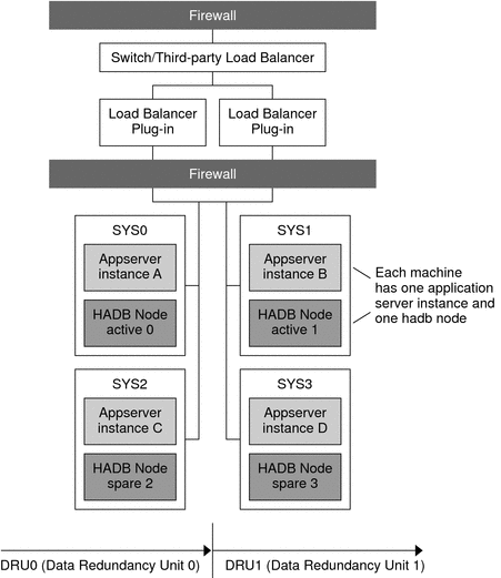
The following figure illustrates an example configuration of the co-located topology.
Figure 3–1 Example Co-located Topology

Machine SYS0 hosts Enterprise Server instance A, machine SYS1 hosts Enterprise Server instance B, machine SYS2 hosts Enterprise Server instance C, and machine SYS3 hosts Enterprise Server instance D.
These four instances form a cluster that persists information to the two DRUs:
-
DRU0 comprises two machines, SYS0 and SYS2. HADB node active 0 is on the machine SYS0. HADB node spare 2 is on the machine SYS2.
-
DRU1 comprises two machines, SYS1 and SYS3. HADB node active 1 is on the machine SYS1. HADB node spare 3 is on the machine SYS3.
Variation of Co-located Topology
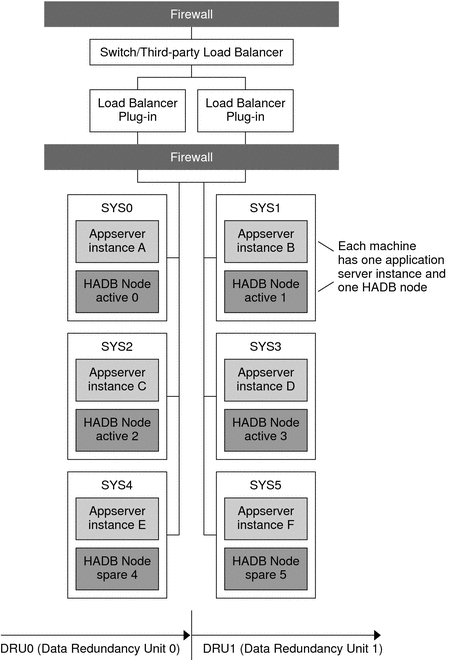
For better scalability and throughput, increase the number of Enterprise Server instances and HADB nodes by adding more machines. For example, you could add two machines, each with one Enterprise Server instance and one HADB node. Make sure to add the HADB nodes in pairs, assigning one node for each DRU. Variation of Co-located Topology illustrates this configuration.
Figure 3–2 Variation of Co-located Topology

In this variation, the machines SYS4 and SYS5 have been added to the co-located topology described in Example Configuration.
Enterprise Server instances are hosted as follows:
-
Machine SYS0 hosts instance A
-
Machine SYS1 hosts instance B
-
Machine SYS2 hosts instance C
-
Machine SYS3 hosts instance D
-
Machine SYS4 hosts instance E
-
Machine SYS5 hosts instance F
These instances form a cluster that persists information to the two DRUs:
-
DRU0 comprises machines SYS0, SYS2, and SYS4. HADB node active 0 is on the machine SYS0. HADB node active 2 is on the machine SYS2. HADB node spare 4 is on the machine SYS4.
-
DRU1 comprises the machines SYS1, SYS3, and SYS5. HADB node active 1 is on the machine SYS1. HADB node active 3 is on the machine SYS3. HADB node spare 5 is on the machine SYS5.
Separate Tier Topology
In this topology, Enterprise Server instances and the HADB nodes are on different machines (hence the name separate tier).
This topology requires more hardware than the co-located topology. It might be a good fit if you have different types of machines—you can allocate one set of machines to host Enterprise Server instances and another to host HADB nodes. For example, you could use more powerful machines for the Enterprise Server instances and less powerful machines for HADB.
Example Configuration
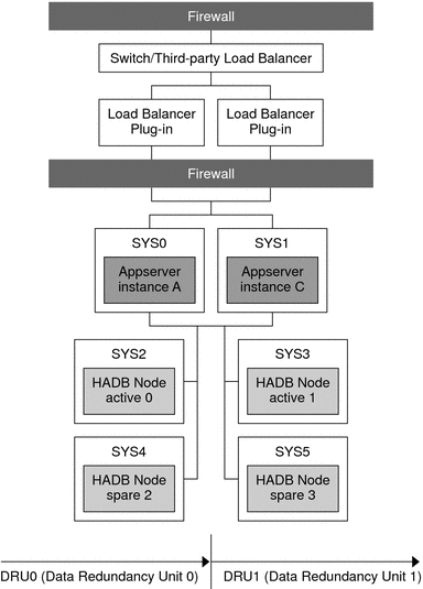
The following figure illustrates the separate tier topology.
Figure 3–3 Example Separate Tier Topology

In this topology, machine SYS0 hosts Enterprise Server instance A and machine SYS1 hosts Enterprise Server instance B. These two instances form a cluster that persists session information to the two DRUs:
-
DRU0 comprises two machines, SYS2 and SYS4. HADB node active 0 is on machine SYS2 and the HADB node spare 2 is on machine SYS4.
-
DRU1 comprises two machines, SYS3 and SYS5. HADB node active 1 is on machine SYS3 and the HADB node spare 3 on machine SYS5.
All the nodes on a DRU are on different machines, so that even if one machine fails, the complete data for any DRU continues to be available on other machines.
Variation of Separate Tier Topology
A variation of the separate tier topology is to increase the number of Enterprise Server instances by adding more machines horizontally to the configuration. For example, add another machine to the example configuration by creating a new Enterprise Server instance. Similarly, increase the number of HADB nodes by adding more machines to host HADB nodes. Recall you must add the HADB nodes in pairs with one node for each DRU.
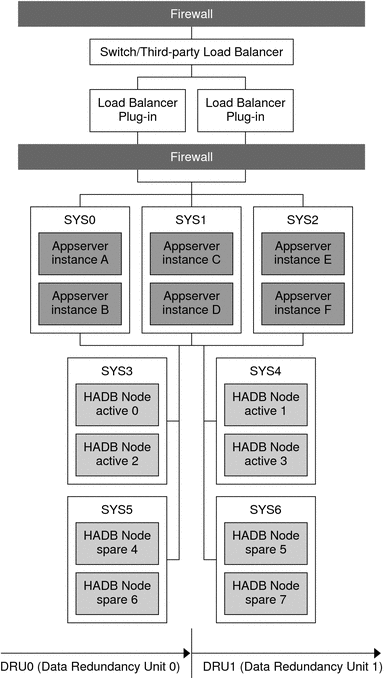
Variation of Separate Tier Topology illustrates this configuration.
Figure 3–4 Variation of Separate Tier Topology

In this configuration, each machine hosting Enterprise Server instances has two instances. There are thus a total of six Enterprise Server instances in the cluster.
HADB nodes are on machines SYS3, SYS4, SYS5, and SYS6.
DRU0 comprises two machines:
-
SYS3, which hosts HADB node active 0 and HADB node active 2.
-
SYS5, with HADB node spare 4 and HADB node spare 6.
DRU1 comprises two machines:
-
SYS4, which hosts HADB node active 1 and HADB node active 3.
-
SYS6, which hosts HADB node spare 5 and HADB node spare 7.
Each machine hosting HADB nodes hosts two nodes. Thus, there are a total of eight HADB nodes: four active nodes and four spare nodes.
Determining Which Topology to Use
To determine which topology (or variation) best meets your performance and availability requirements, test the topologies and experiment with different combinations of machines and CPUs.
Determine what trade-offs are required to meet your goals. For example, if ease of maintenance is critical, the separate tier topology is more suitable. The trade-off is that this topology requires more machines than the co-located topology.
An important factor in the choice of topology is the type of machines available. If the system contains large, Symmetric Multiprocessing (SMP) machines, the co-located topology is attractive because you can take full advantage of the processing power of these machines. If the system contains various types of machines, the separate tier topology can be more useful because you can allocate a different set of machines to the Enterprise Server tier and to the HADB tier. For example, you might want to use the most powerful machines for the Enterprise Server tier and less powerful machines for the HADB tier.
Comparison of Topologies
The following table compares the co-located topology and the separate tier topology. The left column lists the name of the topology, the middle column lists the advantages of the topology, and the right column lists the disadvantages of the topology
Table 3–1 Comparison of Topologies|
Topology |
Advantages |
Disadvantages |
|---|---|---|
|
Co-located Topology |
Requires fewer machines. Because the HADB nodes and the Enterprise Server instances are on the same tier, you are able to create an Enterprise Server instance on each spare node to handle additional load. Improved CPU utilization. Processing is distributed evenly between an Enterprise Server instance and an HADB node sharing one machine. Useful for large, Symmetric Multiprocessing (SMP) machines since it takes full advantage of their processing power. |
Increased complexity of maintenance. For example, when you have to shut down machines hosting HADB nodes to perform maintenance, application server instances on the machine also become unavailable. |
|
Separate Tier Topology |
Easier maintenance. For example, you are able to perform maintenance on the machines that host Enterprise Server instances without having to bring down HADB nodes. Useful with different types of machines. You are able to allocate a different set of machines to the Enterprise Server tier and the HADB tier. For example, you are able to use more powerful machines for the Enterprise Server tier and the less powerful machines for the HADB tier. |
Requires more machines than the co-located topology. Because application server instances and HADB nodes are located on separate tiers, application server instances cannot be located on the machines that host the HADB spare nodes. Reduced CPU utilization. The application server tier and the HADB tier will likely have uneven loads. This is more significant with a small number of machines (four to six). |
- © 2010, Oracle Corporation and/or its affiliates
