Understanding the Status Indicators
|
Introduction
This chapter provides details on the status indicators that appear on the front and back of the J4200/J4400 arrays. This chapter includes the following sections:
Front Status Indicators
This section provides information on the disk drive status indicators.
Two indicators on the front of the Sun Storage J4200/J4400 are located on the right-side end cap of the tray (FIGURE 3-1).
FIGURE 3-1 Indicators on the Front of a Sample J4200 Array

Following are the J4200/J4400 Array front panel status indicator descriptions.
TABLE 3-1 J4200/J4400 Front Panel Status Indicators
|
ID
|
Indicator
|
Color
|
Condition
|
Description
|
|
1
|
System Locate
|
White
|
Off
|
Not supported
|
|
|
|
White
|
Blinking @
1 Hz 50%
|
Location LED is active
|
|
2
|
System OK/ Fault
|
Green
|
On
|
System is powered on
|
|
|
|
Green
|
Blinking @
4 Hz 50%
|
System is booting or being configured
|
|
|
|
Green
|
Off
|
System is powered off
|
|
|
|
Amber
|
Off
|
No current faults
|
|
|
|
Amber
|
On
|
System fault
|
Disk Drives
This section cites the disk drive components and provides descriptions for the indicators.
FIGURE 3-2 shows the disk-release button, the disk handle, and the status indicators.
FIGURE 3-2 Disk Drive

Figure Legend
|
ID
|
Description
|
|
1
|
Release button. Press to the right to disengage the release handle
|
|
2
|
Disk handle
|
|
3
|
OK status indicator
|
|
4
|
Ready to Remove/Fault status indicators
|
Following are the J4200/J4400 disk drive status indicator descriptions.
TABLE 3-2 J4200/J4400 Disk Drive Status Indicators
|
ID
|
Indicator
|
Color
|
Condition
|
Description
|
|
3
|
OK
|
Green
|
On
|
Ready for access
|
|
|
|
Green
|
Blinking
|
Spinning down or accessing drives
|
|
|
|
Green
|
Off
|
Offline or inactive
|
|
4
|
Ready to Remove/Fault
|
Blue
|
On
|
Drives have no pending writes and can be removed safely
|
|
|
|
Amber
|
On
|
HDD fault - Service Action Required
|
|
|
|
Amber
|
Blinking @
4 Hz 50%
|
HDD locator
|
|
|
|
Amber
|
Off
|
No failures
|
Rear Status Indicators
This section describes the status indicators on the back of the J4200/J4400 array.
J4200 SIM Board
Following are the J4200 SIM board components and indicator descriptions.
FIGURE 3-3 J4200 Array SIM Board Components and Status Indicator Descriptions
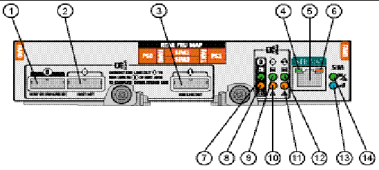
FIGURE 3-4 J4400 Array SIM Board Components and Status Indicator Descriptions
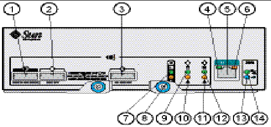
TABLE 3-3 SIM Board Components and Indicator Associations
|
ID
|
Component or Indicator
|
Description
|
|
1
|
Host or SIM Link IN
|
SAS connection to a data or management host, or a connection from another J4200/J4400.
|
|
2
|
Host OUT
|
SAS connection to a host.
|
|
3
|
SIM Link Out
|
SAS connection to another J4200/J4400.
|
|
4
|
Serial Management Port
|
Left Indicator - Green: Serial port is active.
|
|
5
|
Serial Management Port
|
Serial port - Reserved for Sun Customer Support Personnel only.
|
|
6
|
Serial Management Port
|
Right Indicator - Amber: Serial port fault.
|
|
7
|
Host or SIM Link IN
|
Top Indicator - Green
|
|
8
|
Host or SIM Link IN
|
Bottom Indicator - Amber
|
|
9
|
Host OUT
|
Top Indicator - Green
|
|
10
|
Host OUT
|
Bottom Indicator - Amber
|
|
11
|
SIM Link Out
|
Bottom Indicator - Amber
|
|
12
|
SIM Link Out
|
Top Indicator - Green
|
|
13
|
SIM Board
|
Locate Indicator - Blue: Identified as ready for service (not supported)
|
|
14
|
SIM Board
|
Power On/Fault Indicator - Green/Amber
|
SIM Board Status Indicators
Following are the J4200/J4400 SIM board status indicator descriptions:
TABLE 3-4 J4200/J4400 Array SIM Board Status Indicator Descriptions
|
ID
|
Indicator
|
Color
|
Condition
|
Description
|
|
4
|
Serial Management Port
|
Green
|
Serial port is active
|
Left status indicator - serial management connector
|
|
6
|
Serial Management Port
|
Amber
|
Serial port fault
|
Right status indicator - serial management connector
|
|
7 to 12
|
SAS Faults
|
Green/Amber
|
Green is On
Amber is Off
|
Optimal operating status - no activity
|
|
|
Green/Amber
|
Green is Off
Amber is On
|
Link not operating
|
|
|
Green/Amber
|
Green is Blinking
Amber is Off
|
OK with activity
|
|
|
Green/Amber
|
Green is Blinking
Amber is On
|
Link operating with fewer than all four links
|
|
13
|
Locate SIM Board
|
Blue
|
On
|
Identified as ready for service (not supported)
|
|
|
Blue
|
Off
|
Not identified
|
|
14
|
Power SIM Board
|
Green
|
On
|
Power on and system is operating
|
|
|
Green
|
Blinking @ 1 Hz 50%
|
System is booting, being configured, or downloading firmware
|
|
|
Amber
|
Off
|
SIM OK
|
|
|
Amber
|
On
|
SIM fault
|
J4200/J4400 Array Power Supplies

|
Caution - The power supplies in this equipment can produce high energy hazards. Only instructed personnel with authorized access to this equipment can remove and replace modules in the system.
|
FIGURE 3-5 shows J4200 array power supplies and FIGURE 3-6 shows J4400 array power supplies.
FIGURE 3-5 J4200 Array Power Supplies
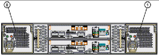
Figure Legend
|
ID
|
Component
|
|
0
|
Power Supply 0
|
|
1
|
Power Supply 1
|
FIGURE 3-6 J4400 Array Power Supplies

FIGURE 3-7 shows an individual J4200 array power supply and FIGURE 3-8 shows an individual J4400 array power supply.
FIGURE 3-7 Individual J4200 Power Supply
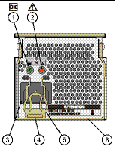
TABLE 3-5 describes the J4200 power supply components and TABLE 3-6 provides the J4200 power supply status indicator descriptions.
TABLE 3-5 J4200 Array Power Supply Components
|
ID
|
Component
|
Description
|
|
1
|
Green indicator
|
See TABLE 3-6.
|
|
2
|
Amber indicator
|
See TABLE 3-6.
|
|
3
|
Universal power input connector
|
Power cord connector.
|
|
4
|
Power supply latch
|
Holds the power supply handle down.
|
|
5
|
Power cord clamp
|
Holds the power cord in place.
|
|
6
|
Power supply handle
|
Used to remove the power supply from and insert the power supply into the J4200 enclosure.
|
J4200 Power Supply Status Indicators
Following are the J4200 power supply status indicator descriptions.
TABLE 3-6 J4200 Power Supply Status Indicators
|
ID
|
Indicator
|
Color
|
Condition
|
Description
|
|
1
|
Power Status
|
Green
|
On
|
AC/DC Power Ready
|
|
|
|
Green
|
Off
|
No AC/DC Power Input
|
|
|
|
Green
|
Blinking
|
AC Present and Standby Output is Available
|
|
2
|
Power Fault
|
Amber
|
On
|
Power Supply Failure
|
|
|
|
Amber
|
Off
|
Power Supply Healthy
|
FIGURE 3-8 Individual J4400 Power Supply
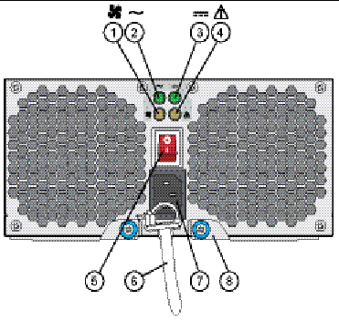
TABLE 3-7 describes the J4400 power supply components and TABLE 3-8 provides the J4400 power supply status indicator descriptions.
TABLE 3-7 J4400 Array Power Supply Components
|
ID
|
Component
|
Description
|
|
1
|
Cooling fan status indicator
|
See TABLE 3-8.
|
|
2
|
AC power status indicator
|
See TABLE 3-8.
|
|
3
|
DC power status indicator
|
See TABLE 3-8.
|
|
4
|
Power supply status indicator
|
See TABLE 3-8.
|
|
5
|
Power on/off switch
|
Turns power to the array on or off.
|
|
6
|
Power cord tie wrap
|
Holds the power cord in place.
|
|
7
|
Universal power input connector
|
Provides power to the array.
|
|
8
|
Right ejection arm and captive screw latch
|
Secures the power supply to the chassis.
|
J4400 Power Supply Status Indicators
Following are the J4400 power supply status indicator descriptions.
TABLE 3-8 J4400 Power Supply Status Indicators
|
ID
|
Indicator
|
Color
|
Condition
|
Description
|
|
1
|
Cooling fan status indicator
|
Amber
|
On
|
Fan failure
|
|
|
|
Amber
|
Off
|
Fans healthy
|
|
2
|
AC power status indicator
|
Green
|
On
|
AC power ready
|
|
|
|
Green
|
Off
|
No AC power input
|
|
3
|
DC power status indicator
|
Green
|
On
|
DC power ready
|
|
|
|
Green
|
Off
|
No DC power input
|
|
4
|
Power supply status indicator
|
Amber
|
On
|
Power supply failure
|
|
|
|
Amber
|
Off
|
Power supply healthy
|
J4200 Array Fan Modules
This section provides the fan module indicator descriptions.
FIGURE 3-9 J4200 Array Fans
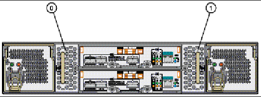
Figure Legend
|
ID
|
Description
|
|
0
|
Fan module 0
|
|
1
|
Fan module 1
|
FIGURE 3-10 Individual J4200 Array Fan Module
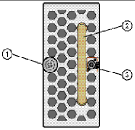
Figure Legend
|
ID
|
Description
|
|
1
|
Thumbscrew
|
|
2
|
Fan module handle
|
|
3
|
Bicolored (green/amber) status indicator
|
J4200 Fan Status Indicators
Following are the J4200 fan status indicator descriptions.
TABLE 3-9 J4200 Fan Status Indicators
|
Indicator
|
Color
|
Condition
|
Description
|
|
Fan Status
|
Green
Amber
|
Off
Off
|
No Power
|
|
|
Green
Amber
|
On
Off
|
Fan Healthy
|
|
|
Green
Amber
|
Off
On
|
Fan Fault
|
Sun Storage J4200/J4400 Array System Overview Storage J4200/J4400 Array System Overview
|
820-3223-14
|
   
|
© © 2009 Sun Microsystems, Inc. All rights reserved.


