JavaScript is required to for searching.
Skip Navigation Links
Exit Print View
Sun Network 10GbE Switch 72p

User’s Guide

search filter icon
search icon

Document Information

Using This Documentation

Product Notes

Related Documentation

CLI Command Modes

Feedback

Support and Accessibility

Understanding the Switch

Switch Overview

Front Panel Components

Rear Panel Components

Confirming Switch Specifications

Physical Specifications

Electrical Specifications

Environmental Specifications

Acoustic Noise Emissions

Installing the Switch

Preparing to Install the Switch

Verify Shipping Kit Contents

Antistatic Precautions

Install the Switch in the Rack

Connecting Management Cables

Management Cable Requirements

NET MGT Port

Connect the NET MGT Cable

SER MGT Port

Connect the SER MGT Cable

Powering On the Switch

Power Cord Specifications

Power On the Switch

Connecting Ethernet Cables

QSFP Cables

SFP+ Cables

Splitter Cables

Ethernet Cable Cautions

Connect Ethernet Cables

Finish the Switch Installation

Administering the Switch

Connecting to the Service Processor

Oracle ILOM Overview

Oracle ILOM Features Not Supported

Verify the DHCP-Assigned IP Address and Host Name

Configure Network Management From CLI (SER MGT)

Log Into Oracle ILOM Web (NET MGT)

Log Into Oracle ILOM CLI (NET MGT)

Log Into Oracle ILOM CLI (SER MGT)

SER MGT Port Configuration Parameters

Configure Network Management From Web

Configure Network Management From CLI (NET MGT)

Log Out of ILOM

Configuring SEFOS User Privileges

Create a SEFOS User

Change a SEFOS User Privilege Level

Update the Firmware

Connecting to SEFOS

SEFOS Overview

Connect to SEFOS

Disconnect From SEFOS

Servicing the Switch

Troubleshooting the Switch

Identifying LEDs

Sensors Overview

Check Switch Status (LEDs)

Check Switch Status (Oracle ILOM)

Component Sensor Targets

Motherboard Sensor Targets

Understanding Service Procedures

Tools Needed for Service

Replaceable Components

Servicing Power Supplies

Power Off a Power Supply

Remove a Power Supply

Install a Power Supply

Power On a Power Supply

Servicing Fans

Remove a Fan

Install a Fan

Servicing Ethernet Cables

Remove an Ethernet Cable

Install an Ethernet Cable

Servicing the Battery

Remove the Battery

Install the Battery

Glossary

Index

Install the Switch in the Rack

Airflow can be established with two different configurations, depending on where you choose to locate the I/O connectors (front of the switch).

  1. Verify that the rack meets the switch specifications.

    See Confirming Switch Specifications.

  2. If installed, open the rack doors.
  3. Assemble the front mounting brackets.

    Perform Steps a-d for each bracket.

    1. Slide the attachment bracket over the long rail, so that the tab on the bracket is opposite the flange of the rail.

      The flat end of the tab is toward the flange, the open end of the tab is toward the rear of the rail.
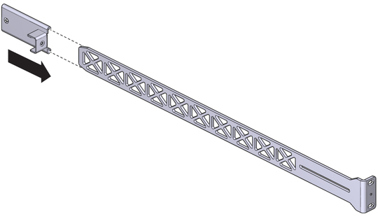
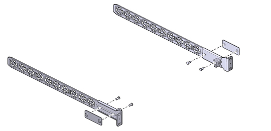
      image:Figure shows the attachement bracket sliding over the long rail
    2. Place the attachment plate on the flange side of the long rail, opposite the attachment bracket.
    3. Use two screws to sandwich the bracket and plate to the rail, in the most forward position.
      image:Figure shows the bracket and plate sandwiching to the rail
    4. Using a No. 2 Phillips screwdriver, tighten the two screws.
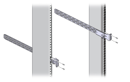
  4. Attach the front mounting brackets to the rack using two captive nuts and two screws for each bracket.

    Tighten the screws securely.


    image:Figure shows the front brackets being installed
  5. Carefully lift the switch and slide it into the rack, from the rear forward.

    Ensure that the ends of the long rails slide into the C-shaped brackets at the front of the switch chassis.
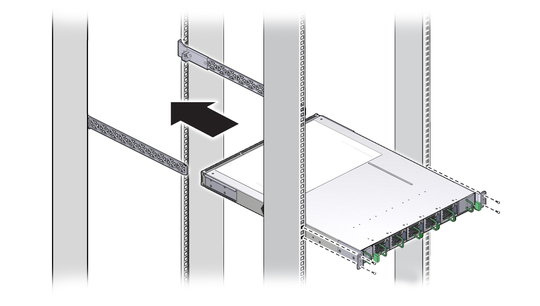

    image:Figure shows the switch sliding into the rack
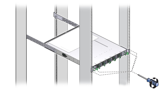
  6. Mount the rear of the switch chassis to the rack posts with two captive nuts and two screws at each side.

    Tighten the screws securely.


    image:Figure shows the switch being secured to the rack
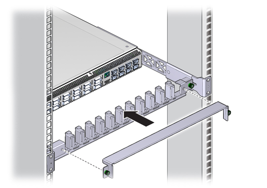
  7. Install the cable management bracket to the tabs of the attachment brackets.

    Tightening the thumbscrews on each side of the cable management bracket.
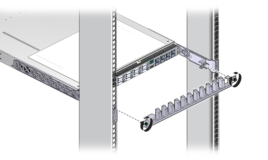

    image:Figure shows the cable management bracket being installed to the switch
  8. Install the cable management bracket cover.
    image:Figure shows the cable management bracket cover being installed
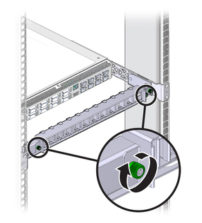
  9. Tighten the thumbscrews on each side of the cover.
    image:Figure shows the thumbscrews being tightened
  10. Attach the management cables.

    See Connecting Management Cables.

Related Information