JavaScript is required to for searching.
Skip Navigation Links
Exit Print View
Sun Blade X6275 M2 Server Module Service Manual
search filter icon
search icon

Document Information

Service Manual Overview

Using This Documentation

Product Information Web Site

Related Books

About This Documentation (PDF and HTML)

Documentation Comments

Contributors

Change History

Server Module and Components Overview

Product Description

Product Features

About the Sun Blade 6000 Modular System Chassis

Illustrated Parts Breakdown

Front Panel LEDs and Features

Power and Reset

Power Modes

Power Button and Power OK LED

Powering On and Off the Server Module

Preparation Procedures for Service and Operation

Preparing the Server for Service

Preparing the Server for Operation

Component Removal and Installation Procedures

Replacing the System Battery

Removing and Installing DIMMs

Removing and Installing Flash Modules

Removing and Installing the Energy Storage Modules

Removing and Installing the Service Processor Board

Removing and Installing USB Flash Drives

Removing and Installing a CPU and Heatsink Assembly

How to Identify a Faulty CPU

How to Remove a CPU and Heatsink Assembly

How to Install a CPU and Heatsink Assembly

How to Replace the Motherboard Assembly

Diagnostic and Maintenance Information and Procedures

Diagnosing Server Module Hardware Faults

BIOS Power-On Self-Test (POST) Codes

Server Module Maintenance Procedures and Information

Specifications

Dimensions

Environmental Specifications

USB Flash Drive Specifications

Index

How to Remove a CPU and Heatsink Assembly


Note - This component is a field-replaceable unit (FRU).


Before You Begin

See How to Identify a Faulty CPU.
  1. Prepare the server module for service. See Preparing the Server for Service.
  2. Identify the faulty CPU. See How to Identify a Faulty CPU.
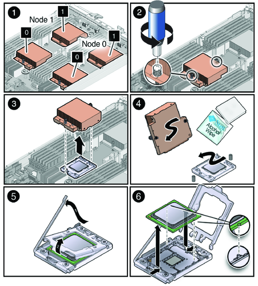
    image:An illustration showing how to remove a CPU and heatsink assembly.
  3. Gently press down on the top of the heatsink to counteract the pressure of the captive spring-loaded screws that secure the heatsink to the motherboard.
  4. Use a number two Phillips screwdriver to alternately loosen each of the two spring-loaded mounting screws that secure the heatsink to the motherboard.

    Note - Alternately turn each screw 180 degrees at a time until the both screws are completely loosened.


  5. To separate the heatsink from the top of the CPU, gently wiggle the heatsink left and right, while pulling upward.

    See frame [3] of the illustration in Step 2.

    A thin layer of thermal compound separates the heatsink and the CPU. This compound also acts as an adhesive.


    Note - Do not allow the thermal compound to contaminate the work space or other components.


  6. Use an alcohol pad to completely remove the thermal compound from the underside of the heatsink.
  7. Remove any dust from the heatsink fins.
  8. Before you remove the CPU, use an alcohol pad to remove the thermal compound from the top of the component.

    See frame [4] of the illustration in Step 2.

  9. To release the processor cover retaining lever, push down on the end of the lever and move it slightly away from the CPU.

    See frame [5] of the illustration in Step 2.

  10. Lift the CPU cover to the fully open position and remove the CPU.

    See frame [6] of the illustration in Step 2.

Next Steps

How to Install a CPU and Heatsink Assembly