| Skip Navigation Links | |
| Exit Print View | |

|
Sun Blade X6275 M2 Server Module Product Documentation |
About This Documentation (PDF and HTML)
Hardware Installation and Product Notes
Overview of the Sun Blade X6275 M2 Server Module
Installing and Powering On the Server Module
Overview of the Sun Blade X6275 M2 Server Module Product Notes
System Software Release Features
Hardware, Firmware, and BIOS Issues
Installing the Oracle Solaris Operating System
Installing Red Hat Enterprise Linux
Installing the SLES Operating System
Introduction to Oracle VM Installation
Creating a PXE Installation Image for Oracle VM
Introduction to Windows Installation
Getting Started With Windows Server 2008 Installation
Installing the Windows Server 2008 R2 Operating System
Updating Critical Drivers and Installing Supplemental Software
Incorporating Device Drivers into a WIM Image for WDS
Administration, Diagnostics, and Service
Overview of the ILOM Supplement
Managing Power Usage and Monitoring Power Consumption
Configuring the Server Power Restore Policy
Switching the Default Serial Port Output Between SP and Host Console
Indicators, Sensors, and Traps
Introduction to Diagnostic Tools
U-Boot Diagnostic Startup Tests
Accessing the Pc-Check Diagnostics Utility on the Tools and Drivers CD/DVD
Server Module and Components Overview
About the Sun Blade 6000 Modular System Chassis
Powering On and Off the Server Module
How to Power the Server Module to Standby Power Mode
How to Power On the Server Module to Full Power Mode
How to Power Off the Server Module
Preparation Procedures for Service and Operation
Preparing the Server for Service
How to Prepare the Server Module for Service
Performing ESD and Antistatic Prevention Measures
Using the Locate LED to Find the Server Module (Optional)
How to Remove the Server Module from the Chassis
How to Remove the Server Module Top Cover
Preparing the Server for Operation
How to Prepare the Server Module for Operation
How to Install the Server Module Top Cover
How to Install the Server Module in the Chassis
Component Removal and Installation Procedures
Battery Replacement Illustration
How to Replace the System Battery
DIMM Slot Designations and Population Order
DIMM Population Rules and Guidelines for the Sun Blade X6275 M2 Server module
Removing and Installing Flash Modules
Removing and Installing the Energy Storage Modules
How to Remove the Energy Storage Modules
How to Install the Energy Storage Modules
Removing and Installing the Service Processor Board
How to Remove the Service Processor Board
How to Install the Service Processor Board
Removing and Installing USB Flash Drives
How to Remove USB Flash Drives
How to Install USB Flash Drives
Removing and Installing a CPU and Heatsink Assembly
How to Remove a CPU and Heatsink Assembly
How to Install a CPU and Heatsink Assembly
How to Replace the Motherboard Assembly
Diagnostic and Maintenance Information and Procedures
Diagnosing Server Module Hardware Faults
Using the DIMM and CPU On-Board Test Circuitry
Clearing CMOS NVRAM and Resetting Passwords
Recovering from Corrupted Service Processor Firmware
BIOS Power-On Self-Test (POST) Codes
How BIOS POST Memory Testing Works
How to Change the POST Options
Server Module Maintenance Procedures and Information
How to Display FRUID Information
How to Back Up FRU Information
Removing and Installing a Server Module Filler Panel
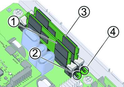
The FMod Power Status LEDs indicate the status of the charged FMod test circuit. The following illustration and table shows the location of the FMods and FMod power

|
See Also: