| Skip Navigation Links | |
| Exit Print View | |

|
Oracle Directory Server Enterprise Edition Deployment Planning Guide 11g Release 1 (11.1.1.5.0) |
| Skip Navigation Links | |
| Exit Print View | |

|
Oracle Directory Server Enterprise Edition Deployment Planning Guide 11g Release 1 (11.1.1.5.0) |
Part I Overview of Deployment Planning for Directory Server Enterprise Edition
1. Introduction to Deployment Planning for Directory Server Enterprise Edition
2. Business Analysis for Directory Server Enterprise Edition
Part II Technical Requirements
3. Usage Analysis for Directory Server Enterprise Edition
4. Defining Data Characteristics
5. Defining Service Level Agreements
6. Tuning System Characteristics and Hardware Sizing
7. Identifying Security Requirements
8. Identifying Administration and Monitoring Requirements
9. Designing a Basic Deployment
10. Designing a Scaled Deployment
Using Load Balancing for Read Scalability
Using Replication for Load Balancing
Assessing Initial Replication Requirements
Load Balancing With Multi-Master Replication in a Single Data Center
Load Balancing With Replication in Large Deployments
Using Server Groups to Simplify Multi-Master Topologies
Using Directory Proxy Server for Load Balancing
Using Distribution for Write Scalability
Using Directory Proxy Server for Distribution
Routing Based on a Custom Algorithm
Using Directory Proxy Server to Distribute Requests Based on Bind DN
Distributing Data Lower Down in a DIT
Logical View of Distributed Data
Directory Server Configuration for Sample Distribution Scenario
Directory Proxy Server Configuration for Sample Distribution Scenario
Using Referrals For Distribution
Using Directory Proxy Server With Referrals
11. Designing a Global Deployment
12. Designing a Highly Available Deployment
Part IV Advanced Deployment Topics
13. Using LDAP-Based Naming With Solaris
14. Deploying a Virtual Directory
In many cases, data distribution is not required at the top of the DIT. However, entries further up the tree might be required by the entries in the portion of the tree that has been distributed. This section provides a sample scenario that shows how to design a distribution strategy in this case.
Example.com has one subtree for groups and a separate subtree for people. The number of group definitions is small and fairly static, while the number of person entries is large, and continues to grow. Example.com therefore requires only the people entries to be distributed across three servers. However, the group definitions, their ACIs, and the ACIs located at the top of the naming context are required to access all entries under the people subtree.
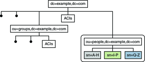
The following illustration provides a logical view of the data distribution requirements.
Figure 10-10 Logical View of Distributed Data

The ou=people subtree is split across three servers, according to the first letter of the sn attribute for each entry. The naming context (dc=example,dc=com) and the ou=groups containers are stored in one database on each server. This database is accessible to entries under ou=people. The ou=people container is stored in its own database.
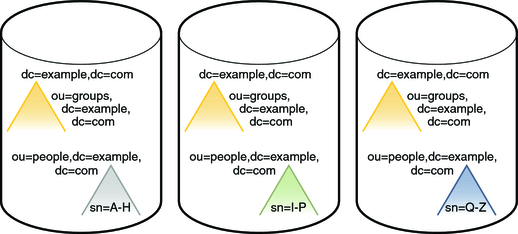
The following illustration shows how the data is stored on the individual Directory Servers.
Figure 10-11 Physical View of Data Storage

Note that the ou=people container is not a subsuffix of the top container.
Each server described previously can be understood as a distribution chunk. The suffix that contains the naming context and the entries under ou=groups, is the same on each chunk. A multi-master replication agreement is therefore set up for this suffix across each of the three chunks.
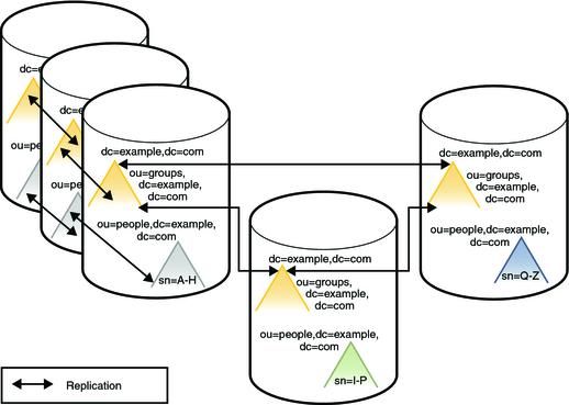
For availability, each chunk is also replicated. At least two master replicas are therefore defined for each chunk.
The following illustration shows the Directory Server configuration with three replicas defined for each chunk. For simplification, the replication agreements are only shown for one chunk, although they are the same for the other two chunks.
Figure 10-12 Directory Server Configuration

Client access to directory data through Directory Proxy Server is provided through data views. For information about data views see Chapter 17, Directory Proxy Server Distribution, in Oracle Directory Server Enterprise Edition Reference.
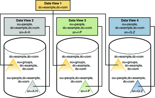
For this scenario, one data view is required for each distributed suffix, and one data view is required for the naming context (dc=example,dc=com) and the ou=groups subtrees.
The following illustration shows the configuration of Directory Proxy Server data views to provide access to the distributed data.
Figure 10-13 Directory Proxy Server Configuration

Distributed data is split according to a distribution algorithm. When you decide which distribution algorithm to use, bear in mind that the volume of data might change, and that your distribution strategy must be scalable. Do not use an algorithm that necessitates complete redistribution of data.
A numeric distribution algorithm based on uid, for example, can be scaled fairly easily. If you start with two data segments of uid=0-999 and uid=1000–1999, it is easy to add third segment of uid=2000–2999 at a later stage.