LEDs and Diagnostic Codes
|
This chapter describes the LEDs and diagnostic codes on the controller tray, drive trays, and the components of the trays.
LED Symbols and General Behavior
TABLE A-1 LED Symbols and Description
|
LED
|
Symbol
|
Location (Modules)
|
Function
|
|
Power
|

|
Power-fan
Interconnect-battery
|
On--The controller has power.
Off--The controller does not have power.
Note - The controller modules do not have a Power LED. They receive their power from the power supplies inside the power-fan modules.
|
|
Battery Fault
|

|
Battery
|
On--The battery is missing or has failed.
Off--The battery is operating normally.
Blinking--The battery is charging.
|
|
Service Action Allowed
|

|
Drive
Power-fan
Controller
Battery
|
On--You can remove the module safely.
See About Service Action Allowed LEDs.
|
|
Service Action Required (Fault)
|

|
Drive
|
On--When the drive tray LED is on, the cable is attached and at least one lane has a link up status, but at least one lane has a link down status.
Off--One of the following conditions exists:
- No cable is attached.
- A cable is attached, and all lanes have a link up status.
- A cable is attached, and all lanes have a link down status.
|
|
Service Action Required (Fault)
|

|
Controller
Power-fan module
|
On--The controller or the power-fan module needs attention.
Off--The controller and the power-fan module are operating normally.
|
|
Locate
|

|
Front frame
|
On--Assists in locating the tray.
|
|
Cache Active
|

|
Controller
|
The activity of the cache is indicated:
On--Data is in the cache.
Off--No data is in the cache.
|
|
Controller Tray Over-Temperature
|

|
Front bezel on the controller tray
|
On--The temperature of the tray has reached an unsafe condition.
Off--The temperature of the tray is within operational range.
|
|
Standby Power
|

|
Front bezel on the controller tray
|
On--The controller tray is in standby mode and the main DC power is off.
Off--The controller tray is not in standby mode and the main DC power is on.
|
|
7-Segment ID Diagnostic Display
|

|
Controller
|
The tray ID or a diagnostic code is indicated (see Controller Tray Diagnostic Code Sequences).
For example, if some of the cache memory dual in-line memory modules (DIMMs) are missing in a controller, error code L8 appears in the diagnostic display (see Controller Tray Lock-Down Codes).
|
|
AC power
|

|
Power-fan module
Note - The LED is directly above or below the AC power switch and the AC power connector.
|
Indicates that the power supply is receiving DC power input.
|
|
DC power
|

|
Power-fan module
Note - The LED is directly above or below the DC power switch and the DC power connector.
|
Indicates that the power supply is receiving DC power input.
|
|
Ethernet Speed and Ethernet Activity
|

|
Controller
|
The speed of the Ethernet ports and whether a link has been established are indicated:
- Left LED On--1-Gb/s speed.
- Left LED Off--100BASE-T or 10BASE-T speed.
- Right LED On--A link is established.
- Right LED Off--No link exists.
- Right LED blinking--Activity is occurring
|
Table describing the LED symbols found on the array components. The location and function is described for these LEDs: Power, Battery Fault, Service Action Allowed, Service Action Required (Fault), Locate, Cache Active, Controller Tray Over-Temperature, Standby Power, Seven-Segment ID Diagnostic Display, AC power LED, DC power LED, and Ethernet Speed and Ethernet Activity LED. About Service Action Allowed LEDs
- Each controller module, power-fan module, and battery module has a Service Action Allowed LED. The Service Action Allowed LED lets you know when you can remove a module safely.

|
Caution - Possible loss of data access--Never remove a controller module, a power-fan module, or a battery module unless the appropriate Service Action Allowed LED is on.
|
- If a controller module or a power-fan module fails and must be replaced, the Service Action Required (Fault) LED on that module comes on to indicate that service action is required. The Service Action Allowed LED also comes on if it is safe to remove the module. If data availability dependencies exist or other conditions that dictate a module should not be removed, the Service Action Allowed LED stays off.
- The Service Action Allowed LED automatically comes on or goes off as conditions change. In most cases, the Service Action Allowed LED comes on when the Service Action Required (Fault) LED comes on for a module.
| Note - If the Service Action Required (Fault) LED comes on but the Service Action Allowed LED is off for a particular module, you might need to service another module first. Check Service Advisor to determine the action that you should take.
|
Disk Drives LEDs
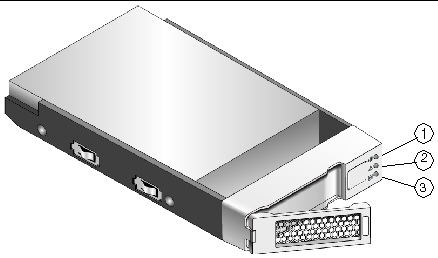
FIGURE A-1 LEDs on Disk Drives

TABLE A-2 Disk Drive LEDs
|
Location
|
LED
|
Color
|
On
|
Blinking
|
Off
|
|
1
|
Service Action Allowed
|
Blue
|
The drive module can be removed safely from the tray.
|
N/A
|
The drive module cannot be removed safely from the tray.
|
|
2
|
Service Action Required
|
Amber
|
An error has occurred.
|
N/A
|
Normal status.
|
|
3
|
Drive Ready/Activity
|
Green
|
The power is turned on, and the drive is operating normally.
|
Drive I/O activity is taking place.
|
The power is turned off.
|
Table describing the state of each disk drive LED.The disk drive LEDs include the service action allowed LED, service action required LED, and the power LED.
TABLE A-3 Disk Drive States Represented by the LEDs
|
Disk Drive State
|
Power
(Green LED)
|
Fault
(Amber LED)
|
|
Power is not applied.
|
Off
|
Off
|
|
Normal operation, power is turned on, no disk drive I/O activity is occurring.
|
On, solid
|
Off
|
|
Normal operation, disk drive I/O activity is occurring.
|
On, blinking
|
Off
|
|
Service action required, a fault condition exists, and the disk drive is offline.
|
On, solid
|
On, solid
|
Controller Tray and Expansion Tray LEDs
The LEDs on the front of the Sun Storage 2540-M2 FC array, Sun Storage 2530-M2 SAS array, and the Sun Storage 2501-M2 expansion tray are identical in appearance and function.
The LEDs are located at the front and back of the trays.
LEDs on the Front of the Trays
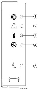
FIGURE A-2 Location of the LEDs on the Front of the Trays

TABLE A-4 Description of the LEDs on the Left End Cap
|
Location
|
LED
|
Color
|
On
|
Off
|
|
1
|
Tray Locate
|
White
|
Identifies a tray that you are trying to find.
|
Normal condition.
|
|
2
|
Service Action Required (Fault)
|
Amber
|
A component within the tray requires attention.
|
The components in the tray are operating normally.
|
|
3
|
Tray Over- temperature
|
Amber
|
The temperature of the tray has reached an unsafe level.
|
The tray temperature is within operational range.
|
|
4
|
Power
|
Green
|
Tray is powered on.
|
Tray is not powered on.
|
|
5
|
Standby Power
|
Green
|
The tray is in Standby Power mode.
|
The tray is not in Standby Power mode.
|
Table describing the location and interpretations of the LEDs on the front of the controller trays and the drive expansion tray.The LEDs include the Tray Locate LED, the Service Action Required (Fault) LED, the Over Temperature LED, Power LED, and Standby Power LED.LEDs on the Rear of the Trays
Controller LEDs on Sun Storage 2500-M2 Arrays
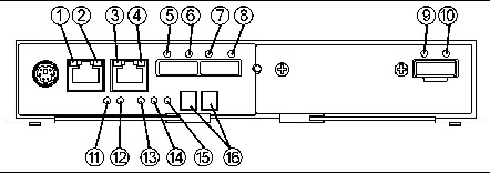
FIGURE A-3 Locations of the Controller LEDs on Sun Storage 2500-M2 Arrays (Rear View)

TABLE A-5 Controller LED Descriptions
|
Location
|
LED
|
Color
|
On
|
Off
|
|
1
|
Ethernet port 1 Link Rate
|
Green
|
Port speed is 1000 Mb/sec.
|
Port speed is 10/100 Mb/sec.
|
|
2
|
Ethernet port 1 Link Active
|
Green
|
The link is up. LED blinks with transmit or receive activity.
|
The link is down or not active.
|
|
3
|
Ethernet port 2 Link Rate
|
Green
|
Port speed is 1000 Mb/sec.
|
Port speed is 10/100 Mb/sec.
|
|
4
|
Ethernet port 2 Link Active
|
Green
|
The link is up. LED blinks with transmit or receive activity.
|
The link is down or not active.
|
|
5
|
Host Link 2
Service Action Required
|
Amber
|
Indicates a fault on one of the ports.
|
Amber and green LEDs off indicates cable unplugged.
|
|
6
|
Host Link 2 Activity
|
Green
|
All links operating.
|
Amber and green LEDs off indicates cable unplugged.
|
|
7
|
Host Link 1
Service Action Required
|
Amber
|
Indicates a fault on one of the ports.
|
Amber and green LEDs off indicates cable unplugged.
|
|
8
|
Host Link 2 Activity
|
Green
|
All links operating.
|
Amber and green LEDs off indicates cable unplugged.
|
|
9
|
Expansion Fault
|
Amber
|
Indicates a fault on one of the links.
|
Amber and green LEDs off indicates cable unplugged.
|
|
10
|
Expansion Activity
|
Green
|
All links operating.
|
Amber and green LEDs off indicates cable unplugged.
|
|
11
|
Battery Fault
|
Amber
|
Battery failure.
|
Battery is operating normally.
|
|
12
|
Battery Charging
|
Green
|
Flashes at 1Hz during charging. On indicates fully charged.
|
Battery faulted or operating without a battery.
|
|
13
|
Service Action Allowed
|
Blue
|
The controller module can be removed safely from the controller tray. (Defaults to On at power-up.)
|
The controller module cannot be removed safely from the controller tray. (Software turns this LED Off during boot.)
|
|
14
|
Service Action Required (Fault)
|
Amber
|
Indicates a fault was detected on the board. (Defaults to On at power up.)
|
Power up self-test sequence has completed. .
|
|
15
|
Cache Active / Cache Offloading
|
Green
|
Battery backup is enabled to support caching activity.
If AC power fails, this LED indicates cache offloading is occurring.
|
Cache is inactive or the controller module has been removed from the controller tray.
|
|
16
|
7-Segment Display
|
Green
|
Displays the tray ID and error codes. See TABLE A-8, TABLE A-9, TABLE A-10, and TABLE A-11.
|
Table listing the name and normal or problem status of the LEDs on the rear of the Sun Storage 2540-M2 FC array controller module.The LEDs include the Ethernet Link Rate LED, Ethernet Link Active LED, Host Link Rate LED, Host Link Active LED, Expansion Fault LED, Expansion Activity LED, Battery Fault LED, Battery Charging LED, Service Action Allowed LED, Service Action Required (Fault) LED, Cache Active/Cache Offloading LED, and the seven-segment display LED.Fibre Channel Host Port LEDs
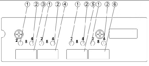
FIGURE A-4 shows the location of the Fibre Channel (FC) host port LEDs.
FIGURE A-4 FC Host Port LEDs on the Sun Storage 2540-M2 (Rear View)

TABLE A-6 FC Host Port LEDs on the Sun Storage 2540-M2 (Rear View)
|
Location
|
Description
|
|
1 and 2
|
Fibre Channel (FC) Link Status LEDs
Note - Both LEDs are green.
LED 1 OFF, LED 2 OFF = No Link
LED 1 ON, LED 2 OFF = 2 Gb/sec Link
LED 1 OFF, LED 2 ON = 4 Gb/sec Link
LED 1 ON, LED 2 ON = 8 Gb/sec Link
|
|
3
|
FC Host Port (Channel 3)
|
|
4
|
FC Host Port (Channel 4)
|
|
5
|
FC Host Port (Channel 5)
|
|
6
|
FC Host Port (Channel 6)
|
Table describing the on and off states of each Fibre Channel host port LED. Power-Fan Module LEDs on Controller Tray and Expansion Tray
The power-fan module LEDs for the Sun Storage 2540-M2 FC array, the Sun Storage 2530-M2 SAS array, and the Sun Storage 2501-M2 Array expansion tray are identical.
FIGURE A-5 Locations of the Power-Fan Module LEDs

TABLE A-7 Descriptions of the Power-Fan Module LEDs
|
Location
|
LED
|
Color
|
On
|
Off
|
|
1
|
Standby Power
|
Green
|
The tray is in Standby mode (5V), and DC power is not available.
|
The tray is not in Standby mode, and DC power is available.
|
|
2
|
DC Power
|
Green
|
DC power from the power-fan module is available and within the specified limits.
|
DC power from the power-fan module is not available.
|
|
3
|
Service Action Allowed
|
Blue
|
The power-fan module can be removed safely from the tray.
|
The power-fan module cannot be removed safely from the tray.
|
|
4
|
Service Action Required
|
Amber
|
Indicates a fault when (a) the power cord is plugged in, the power switch is on and the power supply is not correctly connected to the midplane, or (b) power cord is plugged in, the power switch is on, the power supply is correctly seated in the midplane, and a power supply or blower fault or over- temperature condition exists.
|
Normal status.
|
|
5
|
AC Power
|
Green
|
AC power to the power-fan module is present.
|
AC power to the power-fan module is not present.
|
Table describing the states represented by the power-fan module LEDs. The on and off states of the LEDs are described for the Standby Power LED, DC power LED, service action allowed LED, service action required LED, and AC power LED. Controller Tray Sequence Code Definitions
During normal operation, the tray ID display on each controller module displays the controller tray ID. The Diagnostic LED (lower-digit decimal point) comes on when the display is used for diagnostic codes and goes off when the display is used to show the tray ID.
TABLE A-8 Sequence Code Definitions for the Controller Tray
|
Category
|
Category Code (See Note 1)
|
Detail Codes (See Note 2)
|
|
Startup error
|
SE+ (See Note 3)
|
88+ Power-on default
dF+ Power-on diagnostic fault
|
|
Operational error
|
OE+
|
Lx+ Lock-down codes
(See the following table)
|
|
Operational state
|
OS+
|
OL+ = Offline.
bb+ = Battery backup (operating on batteries)
Cf+ = Component failure
|
|
Component failure
|
CF+
|
dx+ = Processor or cache DIMM.
Cx = Cache DIMM
Px+ = Processor DIMM
Hx+ = Host interface card
Fx+ = Flash drive
|
|
Diagnostic failure
|
dE+
|
Lx+ = Lock-down code
|
|
Category delimiter
|
dash+
|
The separator between category-detail code pairs is used when more than one category detail code pair exists in the sequence.
|
|
End-of-sequence delimiter
|
Blank (See Note 4)
|
The end-of-sequence delimiter is automatically inserted by the hardware at the end of a code sequence.
|
|
Notes:
- A two-digit code that starts a dynamic display sequence.
- A two-digit code that follows the category code with more specific information.
- The plus (+) sign indicates that a two-digit code displays with the Diagnostic LED on.
- No codes display, and the Diagnostic LED is off.
|
Controller Tray Lock-Down Codes
Use the following table to determine the diagnostic lock-down code definitions on the 7-Segment Display in the controller module for the controller tray.
TABLE A-9 Supported Diagnostic Lock-Down Codes on the 7-Segment Display
|
Diagnostic Code
|
Description
|
- -
|
The firmware is booting.
|
.8, 8., or 88
|
This IOM is being held in reset by another IOM.
|
AA
|
The IOM A firmware is in the process of booting (the diagnostic indicator is not yet set).
|
bb
|
The IOM B firmware is in the process of booting (the diagnostic indicator is not yet set).
|
L0
|
The controller types are mismatched, which result in a suspended controller state.
|
L2
|
A persistent memory error has occurred, which results in a suspended controller state.
|
L3
|
A persistent hardware error has occurred, which results in a suspended controller state.
|
L4
|
A persistent data protection error has occurred, which results in a suspended controller state.
|
L5
|
An auto-code synchronization (ACS) failure has been detected, which results in a suspended controller state.
|
L6
|
An unsupported host interface card has been detected, which results in a suspended controller state.
|
L7
|
A sub-model identifier either has not been set or has been mismatched, which results in a suspended controller state.
|
L8
|
A memory configuration error has occurred, which results in a suspended controller state.
|
L9
|
A link speed mismatch condition has been detected in either the IOM or the power supply, which results in a suspended controller state.
|
Lb
|
A host interface card configuration error has been detected, which results in a suspended controller state.
|
LC
|
A persistent cache backup configuration error has been detected, which results in a suspended controller state.
|
Ld
|
A mixed cache memory DIMMs condition has been detected, which results in a suspended controller state.
|
LE
|
Uncertified cache memory DIMM sizes have been detected, which result in a suspended controller state.
|
LF
|
The controller has locked down in a suspended state with limited symbol support.
|
LH
|
A controller firmware mismatch been detected, which results in a suspended controller state.
|
LL
|
The controller cannot access either midplane SBB EEP-ROM, which results in a suspended controller state.
|
Ln
|
A module is not valid for a controller, which results in a suspended controller state.
|
LP
|
Drive port mapping tables are not detected, which results in a suspended controller state.
|
LU
|
The start-of-day (SOD) reboot limit has been exceeded, which results in a suspended controller state.
|
Controller Tray Diagnostic Code Sequences
TABLE A-10 Diagnostic Code Sequences for the Controller Tray
|
Displayed Diagnostic Code Sequences
|
Description
|
SE+ 88+ blank-
|
One of the following power-on conditions exists:
Controller power-on
Controller insertion
Controller inserted while held in reset
|
xy -
|
Normal operation.
|
OS+ Sd+ blank-
|
Start-of-day (SOD) processing.
|
OS+ OL+ blank-
|
The controller is placed in reset while displaying the tray ID.
|
OS+ bb+ blank-
|
The controller is operating on batteries (cache backup).
|
OS+ CF+ Hx + blank-
|
A failed host card has been detected.
|
OS+ CF+ Fx + blank-
|
A failed flash drive has been detected.
|
SE+ dF + blank-
|
A non-replaceable component failure has been detected.
|
SE+ dF + dash+ CF+ Px + blank-
|
A processor DIMM failure has been detected.
|
SE+ dF + dash+ CF+ Cx + blank-
|
A cache memory DIMM failure has been detected.
|
SE+ dF + dash+ CF+ dx + blank-
|
A processor or cache DIMM failure has been detected.
|
SE+ dF + dash+ CF+ Hx + blank-
|
A host card failure has been detected.
|
OE+ Lx + blank-
|
A lockdown condition has been detected.
|
OE+ L2+ dash+ CF+ Px + blank-
|
Persistent processor DIMM ECC errors have been detected, which result in a suspended controller state.
|
OE+ L2+ dash+ CF+ Cx + blank-
|
Persistent cache DIMM ECC errors have been detected, which result in a suspended controller state.
|
OE+ L2+ dash+ CF+ dx + blank-
|
Persistent processor or cache DIMM ECC errors have been detected, which result in a suspended controller state.
|
OE+ LC+ blank-
|
The write-protect switch is set during cache restore, which results in a suspended controller state.
|
OE+ LC+ dd + blank-
|
The memory size is changed from bad data in the flash drives, which results in a suspended controller state.
|
DE+ L2+ dash+ CF+ Cx + blank-
|
A cache memory diagnostic has been reported failed, which results in a suspended controller state.
|
Table describing the diagnostic code sequeneces for controller tray components. Expansion Tray 7-Segment Display
- During normal operation, the tray ID display on each IOM displays the expansion tray ID. The Diagnostic LED (lower-digit decimal point) comes on when the display is used for diagnostic codes and goes off when the display is used to show the tray ID.
- If a power-on or reset occurs, the Diagnostic LED, the Heartbeat LED (upper-digit decimal point), and all seven segments of both digits come on. The Diagnostic LED remains on until the expansion tray ID appears.
TABLE A-11 Supported Diagnostic Codes
|
Diagnostic Code
|
IOM State
|
Description
|
.8, 8., or 88
|
Suspended
|
This IOM is being held in reset by another IOM.
|
L0
|
Suspended
|
The IOM types are mismatched.
|
L2
|
Suspended
|
A persistent memory error has occurred.
|
L3
|
Suspended
|
A persistent hardware error has occurred.
|
L9
|
Suspended
|
An over-temperature condition has been detected in either the IOM or the power supply.
|
LL
|
Suspended
|
The midplane SBB VPD EEPROM cannot be accessed.
|
Ln
|
Suspended
|
The IOM module is not valid for this drive tray.
|
LP
|
Suspended
|
Drive port mapping tables are not found.
|
H0
|
Suspended
|
An IOM Fibre Channel interface failure has occurred.
|
H1
|
Suspended
|
An SFP transceiver speed mismatch (a 2-Gb/s SFP transceiver is installed when the drive tray is operating at 4 Gb/s) indicates that an SFP transceiver must be replaced. Look for the SFP transceiver with a blinking amber LED.
|
H2
|
Suspended
|
The IOM configuration is invalid or incomplete, and it operates in a Degraded state.
|
H3
|
Suspended
|
The maximum number of IOM reboot attempts has been exceeded.
|
H4
|
Suspended
|
This IOM cannot communicate with the alternate IOM.
|
H5
|
Suspended
|
A midplane harness failure has been detected in the drive tray.
|
H6
|
Suspended
|
An IOM firmware failure has been detected.
|
H8
|
|
SFP transceivers are present in currently unsupported IOM slots, either 2A or 2B. Secondary trunking SFP transceiver slots 2A and 2B are not supported. Look for the SFP transceiver with the blinking amber LED, and remove it.
|
H9
|
|
A non-catastrophic hardware failure has occurred. The IOM is operating in a Degraded state.
|
J0
|
Suspended
|
The IOM module is incompatible with the drive tray firmware.
|
Table describing the diagnostic code sequeneces for expansion drive tray and state of the input/output module.
| Sun Storage 2500-M2 Arrays Hardware Installation Guide
|
E20740-01
|
   
|
© © 2011, Oracle and/or its affiliates. All rights reserved.


