| Oracle® Fusion Middleware Application Adapter for Siebel User's Guide for Oracle WebLogic Server 11g Release 1 (11.1.1.4.0) E17056-04 |
|
 Previous |
 Next |
| Oracle® Fusion Middleware Application Adapter for Siebel User's Guide for Oracle WebLogic Server 11g Release 1 (11.1.1.4.0) E17056-04 |
|
 Previous |
 Next |
OracleAS Adapter for Siebel integrates seamlessly with Oracle Service Bus (OSB) to facilitate Web service integration. OSB is based on the Service-Oriented Architecture (SOA). It consumes adapter services exposed as Web Service Definition Language (WSDL) documents.
This chapter contains the following topics:
Overview of Application Adapter Integration with Oracle Service Bus
Configuring Outbound Processing Using Oracle Service Bus (J2CA Configuration)
Configuring Inbound Processing Using Oracle Service Bus (J2CA Configuration)
Configuring Outbound Processing Using Oracle Service Bus (BSE Configuration)
To integrate with Oracle Service Bus (OSB), OracleAS Adapter for Siebel must be deployed in the same Oracle WebLogic Server as OSB. The underlying adapter services must be exposed as WSDL files, which are generated during design time in Oracle Adapter Application Explorer (Application Explorer) for both request-response (outbound) and event notification (inbound) services of the adapter.
This section describes how to configure outbound processing using Oracle Service Bus for J2CA configurations.
Samples have been provided for this usecase scenario in the etc/sample folder in the Application Adapters installation.
This section includes the following topics:
Setting the Class Path for Application Explorer to Integrate With Oracle Service Bus
Publishing a WSDL From Application Explorer to Oracle Service Bus
Perform the following steps to start Oracle Service Bus and create project folders:
Start the Oracle WebLogic Server for the Oracle WebLogic Server domain that you have configured.
Open the Oracle Service Bus Console in a Web browser by entering the following URL:
http://hostname:port/sbconsole
Where hostname is the name of the machine where Oracle WebLogic Server is running and port is the port for the domain you are using. The port for the default domain is 7001.
The Oracle Service Bus Console logon page is displayed.
Log on to the Oracle Service Bus Console using a valid user name and password.
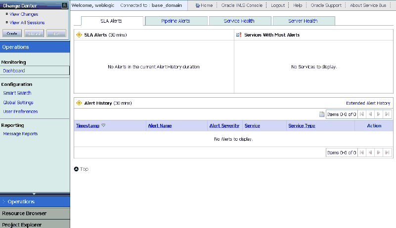
The Oracle Service Bus Console home page is displayed, as shown in Figure 7-1.
Figure 7-1 Oracle Service Bus Console Home Page
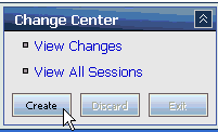
Click Create in the Change Center area to start a new Oracle Service Bus session, as shown in Figure 7-2.
Figure 7-2 Create Button Selected in the Change Center
Click Project Explorer in the left pane, as shown in Figure 7-3.
The Project Explorer page is displayed, as shown in Figure 7-4.
Provide a valid name for the new project (for example, Siebel_Project) and click Add Project.
The new project is successfully created and listed in the left pane.
Click the new project node in the left pane.
The project page is displayed, as shown in Figure 7-5.
Figure 7-5 The Enter New Folder Name Field

In the Enter New Folder Name field, type Business Service and click Add Folder.
In the Enter New Folder Name field, type Proxy Service and click Add Folder.
In the Enter New Folder Name field, type wsdls and click Add Folder.
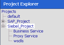
The Business Service, Proxy Service, and wsdls folders are listed in the left pane below the new Siebel_Project node, as shown in Figure 7-6.
Figure 7-6 Business Service, Proxy Service, and wsdls Folders Listed Below the Project Node
Click Activate in the Change Center.
The Activate Session page is displayed, as shown in Figure 7-7.
Click Submit.
Before starting and using Application Explorer to publish a WSDL directly to the Oracle Service Bus (OSB) Console (project/folder), OSB users must perform the following steps:
Open the command prompt window.
Navigate to the following directory:
<OSB_Home>\user_projects\domains\base_domain\bin
Execute setDomainEnv.cmd (Windows) or . ./setDomainEnv.sh (UNIX/Linux).
This command sets the class path for Application Explorer to access the Oracle WebLogic Server APIs to publish the WSDLs to the OSB Console.
Do not close the command prompt window.
Navigate to the following directory:
<OSB_Home>\3rdparty\ApplicationAdapters\tools\iwae\bin
Execute ae.bat (Windows) or iwae.sh (UNIX/Linux) to start Application Explorer.
You are now ready to publish WSDLs from Application Explorer to the OSB Console.
Perform the following steps to publish a WSDL from Application Explorer to Oracle Service Bus:
Start Application Explorer, connect to a J2CA configuration, and connect to a Siebel target.
For more information, see Chapter 2, "Configuring Oracle Application Server Adapter for Siebel".
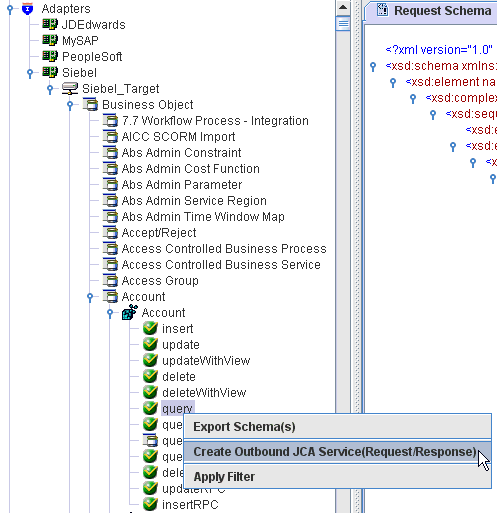
Expand Business Object, Account, and then Account.
Right-click the query method and select Create Outbound JCA Service(Request/Response) from the menu, as shown in Figure 7-8.
Figure 7-8 Create Outbound JCA Service(Request/Response) Option
The Export WSDL dialog is displayed, as shown in Figure 7-9.
In the Name field, a default file name for the WSDL file is provided. You can accept the default or provide your own.
Select the Export to OSB option.
In the Location field, enter the folder name in Oracle Service Bus where you want to publish the WSDL document.
The location is composed of an Oracle Service Bus project name and optionally, one or more folder names. The project name and any folder names must be separated by a forward slash character “/”.
In the Host field, enter the name of the machine where Oracle Service Bus is installed.
In the Port field, enter the port that is being used by Oracle Service Bus.
In the User field, enter your username to access Oracle Service Bus.
In the Password field, enter your password to access Oracle Service Bus.
Click OK.
The WSDL is published to the location specified in the Export WSDL dialog and is now available for use with a Business Service or Proxy Service in Oracle Service Bus.
Perform the following steps to configure a WSDL-based Business Service:
As shown in Figure 7-10, open the Oracle Service Bus Console and select the created WSDL folder in the left pane (for example, wsdls).
Ensure that the exported WSDL is listed, as shown in Figure 7-11.
Click the icon that corresponds to the exported WSDL in the Actions column.
The Generate WSDL and Service page is displayed, as shown in Figure 7-12.
Figure 7-12 Generate WSDL and Service Page
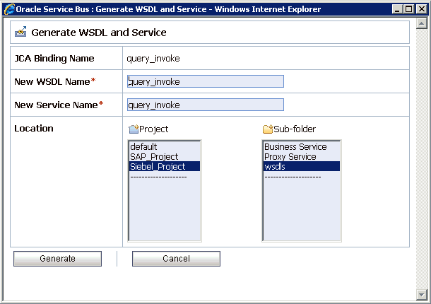
Provide a new WSDL name and a new service name in the corresponding fields, as shown in Figure 7-13.
Figure 7-13 Generate WSDL and Service Page
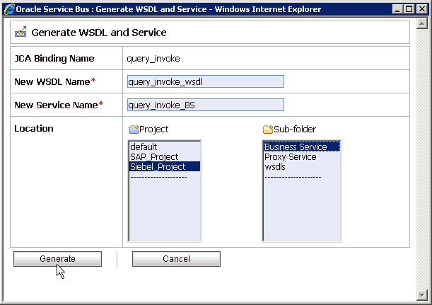
In the Location area, select an available project and the sub-folder that is designated for Business Services.
Click Generate.
If the WSDL and Service resources are successfully created, then the following message is displayed, as shown in Figure 7-14.
Figure 7-14 WSDL and Service Resources Generated Successfully Message

Perform the following steps to configure a File type Business Service:
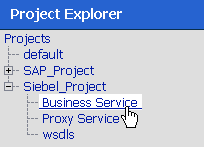
As shown in Figure 7-15, select the Business Service folder you created in the left pane.
Figure 7-15 Business Service Folder Selected in the Project Explorer
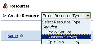
In the right pane, select Business Service from the Create Resource menu, as shown in Figure 7-16.
Figure 7-16 Business Service Selected from the Create Resource Menu
As shown in Figure 7-17, the General Configuration page is displayed.
Provide a name for the new Business Service and select Messaging Service from the Service Type area.
Click Next.
The Message Type Configuration page is displayed, as shown in Figure 7-18.
Figure 7-18 Message Type Configuration Page
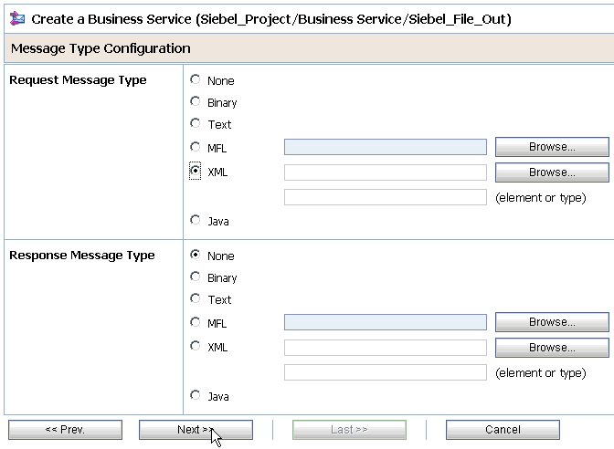
Select XML as the Request Message Type and None as the Response Message Type.
Click Next.
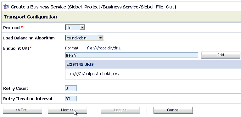
The Transport Configuration page is displayed, as shown in Figure 7-19.
Select file from the Protocol list.
Enter the path to a destination folder on your file system in the Endpoint URI field and click Add.
Click Next, as shown in Figure 7-20.
Figure 7-20 Next Button in the Transport Configuration Page
The FILE Transport Configuration page is displayed, as shown in Figure 7-21.
Figure 7-21 FILE Transport Configuration Page
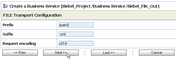
Enter the prefix and suffix for the output file to be received and click Next.
The Message Handling and Advanced Settings page is displayed, as shown in Figure 7-22.
Figure 7-22 Message Handling and Advanced Settings Page

Click Next.
The following Summary page is displayed, as shown in Figure 7-23.
Review all the information for your Business Service and click Save.
Perform the following steps to configure a Proxy Service:
As shown in Figure 7-24, select the Proxy Service folder you created in the left pane.
Figure 7-24 Proxy Service Selected from the Create Resource Menu
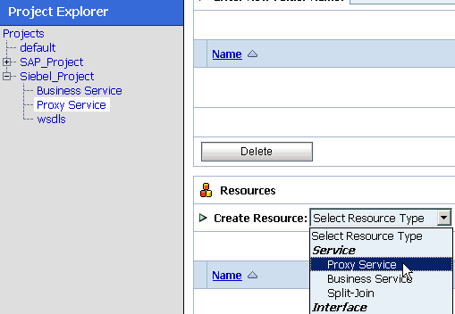
In the right pane, select Proxy Service from the Create Resource menu.
The General Configuration page is displayed, as shown in Figure 7-25.
Provide a name for the Proxy Service and from the Service Type area select Any XML Service.
Click Next, as shown in Figure 7-26.
Figure 7-26 Next Button in the Transport Configuration Page
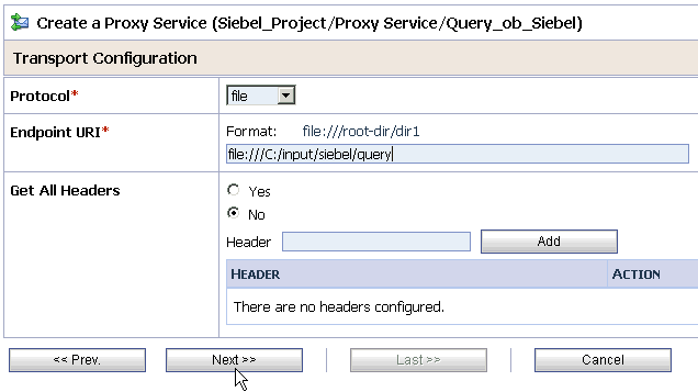
Select file from the Protocol list.
Enter the path to an input folder on your file system in the Endpoint URI field.
Click Next, as shown in Figure 7-27.
Figure 7-27 FILE Transport Configuration Page
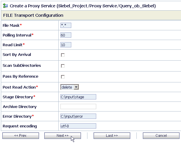
Provide any folder locations on your file system for the Stage Directory and Error Directory fields.
Click Next, as shown in Figure 7-28.
Accept the default values and click Next.
The following Summary page is displayed, as shown in Figure 7-29.
Review all the information for your Proxy Service and click Save.
Check if the success message is displayed, as shown in Figure 7-30.
Figure 7-30 Proxy Service Created Successfully Message

Perform the following steps to configure a Pipeline:
As shown in Figure 7-31, click the Edit Message Flow icon in the row of the Proxy Service you created.
The Edit Message Flow workspace area is displayed, as shown in Figure 7-32.
Figure 7-32 Edit Message Flow Workspace Area

Click the Proxy Service icon and select Add Pipeline Pair from the menu, as shown in Figure 7-33.
Click the PipelinePairNode1 icon and select Add Route from the menu, as shown in Figure 7-34.
The RouteNode1 icon is added below the Request Pipeline icon, as shown in Figure 7-35.
Click the RouteNode1 icon and select Edit Route from the menu.
As shown in Figure 7-36, the Edit Stage Configuration workspace area is displayed.
Figure 7-36 Edit Stage Configuration Workspace Area
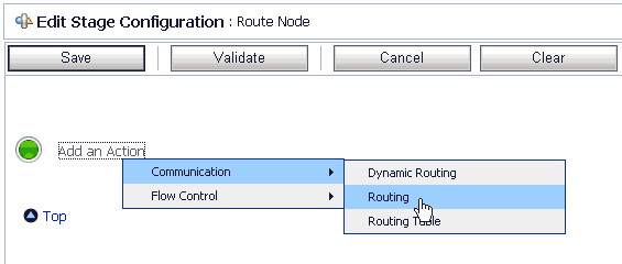
As shown in Figure 7-37, click Add an Action, select Communication from the menu, and click Routing.
Figure 7-37 Edit Stage Configuration Workspace Area
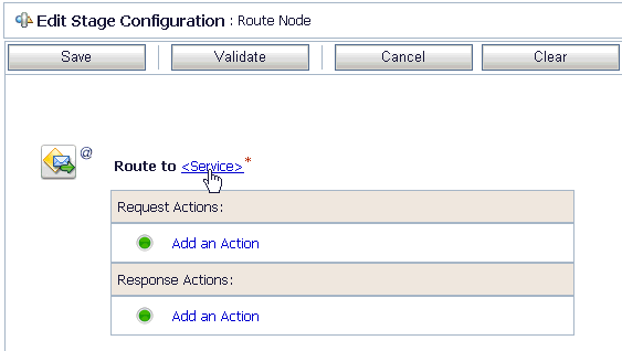
Click <Service>.
The Select Service dialog is displayed, as shown in Figure 7-38.
Select the WSDL type Business Service configured for Siebel and click Submit.
As shown in Figure 7-39, you are returned to the Edit Stage Configuration workspace area.
Figure 7-39 Edit Stage Configuration Workspace Area
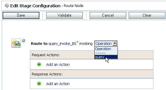
Select the name of the Siebel business object (for example, Query) as the operational attribute from the list, as shown in Figure 7-40.
Figure 7-40 Business Object Selected as the Operational Attribute
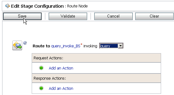
Click Save.
As shown in Figure 7-41, click the Response Pipeline icon and select Add Stage from the menu.
The Stage1 icon is added below the Response Pipeline icon, as shown in Figure 7-42.
Click the Stage1 icon and select Edit Stage from the menu.
The Edit Stage Configuration workspace area is displayed, as shown in Figure 7-43.
Figure 7-43 Edit Stage Configuration Workspace Area
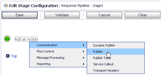
Click Add an Action, select Communication from the menu, and click Publish, as shown in Figure 7-44.
Figure 7-44 Edit Stage Configuration Workspace Area
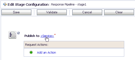
Click <Service>.
As shown in Figure 7-45, the Select Service dialog is displayed.
Select a File type Business Service and click Submit.
You are returned to the Edit Stage Configuration workspace area, as shown in Figure 7-46.
Figure 7-46 Edit Stage Configuration Workspace Area
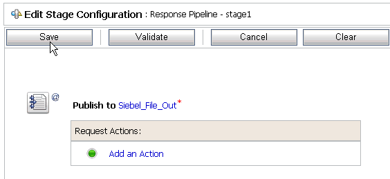
Click Save.
You are returned to the Edit Message Flow workspace area, as shown in Figure 7-47.
Figure 7-47 Edit Message Flow Workspace Area
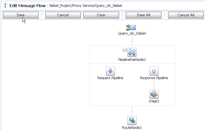
Click Save.
Figure 7-48 Message Flow Created Successfully Message

As shown in Figure 7-48, check if the success message is displayed and click Activate in the Change Center.
The Activate Session page is displayed, as shown in Figure 7-49.
Click Submit.
As shown in Figure 7-50, check if the View Configuration Changes page is displayed.
Figure 7-50 View Configuration Changes Page

As shown in Figure 7-51, copy and paste an input XML file in the input folder you have configured.
Figure 7-51 An Input XML File in the Configured Folder

Output is received in the configured output location.
This section describes how to configure inbound processing using Oracle Service Bus for J2CA configurations.
Samples have been provided for this usecase scenario in the etc/sample folder in the Application Adapters installation.
This section includes the following topics:
Setting the Class Path for Application Explorer to Integrate With Oracle Service Bus
Publishing a WSDL From Application Explorer to Oracle Service Bus
Perform the following steps to start Oracle Service Bus and create project folders:
Start the Oracle WebLogic Server for the Oracle WebLogic Server domain that you have configured.
Open the Oracle Service Bus Console in a Web browser by entering the following URL:
http://hostname:port/sbconsole
Where hostname is the name of the machine where Oracle WebLogic Server is running and port is the port for the domain you are using. The port for the default domain is 7001.
The Oracle Service Bus Console logon page is displayed.
Log on to the Oracle Service Bus Console using a valid user name and password.
The Oracle Service Bus Console home page is displayed, as shown in Figure 7-52.
Figure 7-52 Oracle Service Bus Console Home Page

As shown in Figure 7-53, click Create in the Change Center area to start a new Oracle Service Bus session.
Figure 7-53 Create Button in Change Center

Click Project Explorer in the left pane, as shown in Figure 7-54.
The Project Explorer page is displayed, as shown in Figure 7-55.
Provide a valid name for the new project and click Add Project.
The project is successfully created and listed.
Click on the created project.
The project page is displayed, as shown in Figure 7-56.
Figure 7-56 Enter New Folder Name Field in Project Page

In the Enter New Folder Name field, type Business Service and click Add Folder.
In the Enter New Folder Name field, type Proxy Service and click Add Folder.
In the Enter New Folder Name field, type wsdls and click Add Folder.
The Business Service, Proxy Service, and wsdls folders are listed in the left pane below the project node, as shown in Figure 7-57.
Figure 7-57 Business Service, Proxy Service, and wsdls Folders Listed in Project Explorer

Before starting and using Application Explorer to publish a WSDL directly to the Oracle Service Bus (OSB) Console (project/folder), OSB users must perform the following steps:
Open the command prompt window.
Navigate to the following directory:
<OSB_Home>\user_projects\domains\base_domain\bin
Execute setDomainEnv.cmd (Windows) or . ./setDomainEnv.sh (UNIX/Linux).
This command sets the class path for Application Explorer to access the Oracle WebLogic Server APIs to publish the WSDLs to the OSB Console.
Do not close the command prompt window.
Navigate to the following directory:
<OSB_Home>\3rdparty\ApplicationAdapters\tools\iwae\bin
Execute ae.bat (Windows) or iwae.sh (UNIX/Linux) to start Application Explorer.
You are now ready to publish WSDLs from Application Explorer to the OSB Console.
This section describes how to publish a WSDL from Application Explorer to Oracle Service Bus.
Creating a Channel
Before publishing a WSDL, you must first create a separate channel for every inbound J2CA service and select that channel when you generate WSDL for inbound interaction using Application Explorer.
To create a channel:
In the left pane, click Events.
Expand the Siebel node.
The ports and channels nodes appear in the left pane.
Right-click Channels and select Add Channel, as shown in Figure 7-58.
The Add Channel dialog is displayed, as shown in Figure 7-59.
Perform the following steps:
Enter a name for the channel, for example, SiebelEvent.
Enter a brief description.
From the Protocol list, select HTTP Listener, MQ Series Listener, or File Listener.
For demonstration purposes, this procedure uses the HTTP Listener as an example.
Click Next.
The Basic dialog is displayed, as shown in Figure 7-60.
Enter the system information as specified in the following table:
| Parameter | Description |
|---|---|
| Listener port | Port on which to listen for Siebel event data. |
| Https | For a secure HTTP connection, select the Https check box.
This option is currently not supported. |
| Synchronization Type | Select REQUEST_RESPONSE from the list, which is the recommended option. |
| Encoding Type | Choose an encoding type to be used from the list. By default, ASCII is selected. |
As shown in Figure 7-61, click the PreParser tab.
Specify the location of the schema file that was generated for the Integration Object node using the Export Schema(s) option in Application Explorer.
|
Note: During run time, the Oracle Application Adapter for Siebel adds the namespace to the Siebel published document using the schema that is specified in the PreParser tab. If the Schema location field in the PreParser tab is left blank, then OSB processes do not work properly as the Siebel published documents do not contain any namespaces. |
Click OK.
The channel appears under the channels node in the left pane. An X over the icon indicates that the channel is currently disconnected, as shown in Figure 7-62.
You must now create an Integration Object node.
Creating an Integration Object Node
Start Application Explorer.
Expand the Adapters node, as shown in Figure 7-63.
Figure 7-63 Disconnected Siebel Target Node

Perform the following steps:
Expand the Siebel node.
The defined Siebel targets are displayed under the adapter node.
Click the target name, for example, siebel, under the Siebel node.
The Connection dialog displays the values you entered.
Verify your connection parameters.
Right-click the target name and select Connect.
The x icon disappears, indicating that the node is connected, as shown inFigure 7-64.
Expand the Integration Object node and select Sample Account.
Right-click the Sample Account node and select Add IO Node.
The Add IO Node dialog is displayed, as shown in Figure 7-65.
Enter a node name (for example, Sample_Account) in the Node name field and a path to the Sample Account XSD file in the Schema location field.
Please note:
For Siebel 7.5 or later: Generate XSD schemas directly from Siebel tools. You use the XSD schemas when you create Web services in Application Explorer. After you generate an XSD schema through Siebel tools, use it to create an IO node and a Web service.
For Siebel 7.0: You cannot generate XSD schemas directly from Siebel tools; only XDR schemas can be created. Before you create a Web service, you must first generate an XSD schema from the XDR schema using Application Explorer.
If the XSD schema has already been generated, then select XSD Schema. If you are using Siebel-generated XDR schemas, then do not select the XSD schema option.
Select a protocol (HTTP, FILE, or MQ Series) from the Protocol list.
Click Continue.
The new Integration Object node is added, as shown inFigure 7-66.
Generating WSDL for Event Notification
After you create a channel and an associated Integration Object node, you must generate WSDL for the event using Application Explorer.
You must be connected to a Siebel target under the Adapters node in Application Explorer. For detailed information on how to define and connect to a target, see "Establishing a Connection (Target) for Siebel".
After you connect to a Siebel target, generate WSDL for the event as follows:
As shown in Figure 7-67, right-click the Integration Object node (for example, Sample_Account), and then select Create Inbound JCA Service (Event).
Figure 7-67 Create Inbound JCA Service (Event) Option
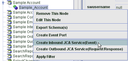
The Export WSDL dialog is displayed, as shown in Figure 7-68.
|
Note: The schema validation options (Root, Namespace, Schema) are not applicable for the Oracle Application Adapter for Siebel. |
In the Name field, a default file name for the WSDL file is provided. You can accept the default or provide your own.
From the Channel list, select the channel you created for this inbound service.
Select the Export to OSB option.
In the Location field, enter the folder name in Oracle Service Bus where you want to publish the WSDL document.
The location is composed of an Oracle Service Bus project name and optionally, one or more folder names. The project name and any folder names must be separated by a forward slash character “/”.
In the Host field, enter the name of the machine where Oracle Service Bus is installed.
In the Port field, enter the port that is being used by Oracle Service Bus.
In the User field, enter your username to access Oracle Service Bus.
In the Password field, enter your password to access Oracle Service Bus.
Click OK.
The inbound WSDL is published to the location specified in the Export WSDL dialog and is now available for use with a Proxy Service in Oracle Service Bus.
Perform the following steps to configure a WSDL-based Proxy Service:
As shown in Figure 7-69, open the Oracle Service Bus Console and select the created WSDL folder in the left pane (for example, wsdls).
Figure 7-69 Created WSDL Folder Selected in the Project Explorer
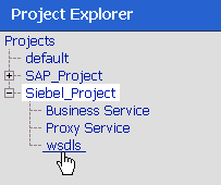
Ensure that the exported WSDL is listed, as shown in Figure 7-70.
Click the icon that corresponds to the exported WSDL in the Actions column.
The Generate WSDL and Service page is displayed, as shown in Figure 7-71.
Figure 7-71 Generate WSDL and Service Page
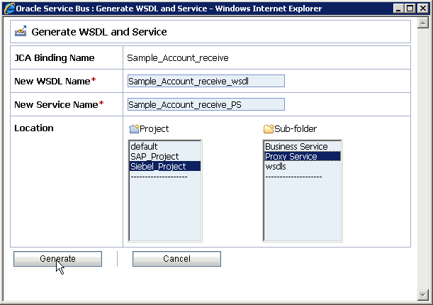
Provide a new WSDL name and a new service name in the corresponding fields.
In the Location area, select an available project and the sub-folder that is designated for Proxy Services.
Click Generate.
If the WSDL and Service resources are successfully created, then the following message is displayed, as shown in Figure 7-72.
Figure 7-72 WSDL and Service Resources Successfully Created Message

Click Proxy Service under Project Explorer and check if the generated WSDL and Proxy Service are listed, as shown in Figure 7-73.
Perform the following steps to configure a File type Business Service:
Select the Business Service folder you created in the left pane, as shown in Figure 7-74.
Figure 7-74 Business Service Folder Selected in the Project Explorer

In the right pane, select Business Service from the Create Resource menu, as shown in Figure 7-75.
Figure 7-75 Business Service Selected from the Create Resource Menu

The General Configuration page is displayed, as shown in Figure 7-76.
Provide a name for the Business Service and from the Service Type area select Messaging Service.
Click Next.
As shown in Figure 7-77, the Message Type Configuration page is displayed.
Figure 7-77 Message Type Configuration Page
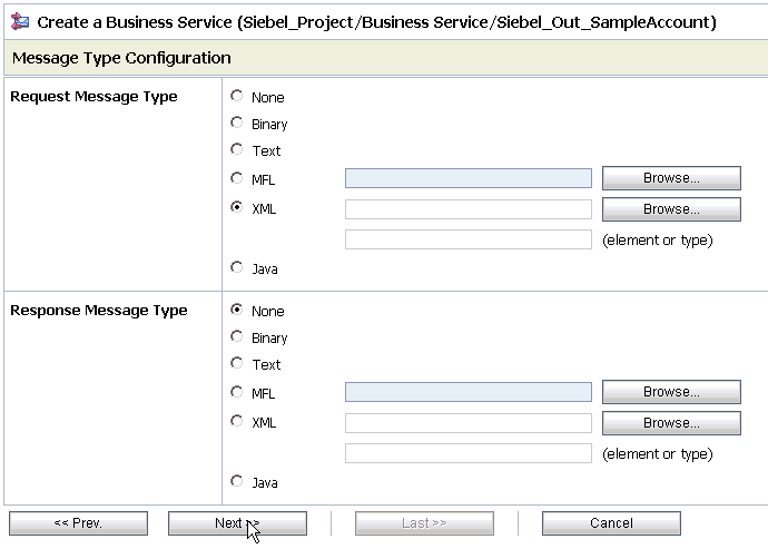
Select XML as the Request Message Type and None as the Response Message Type.
Click Next.
The Transport Configuration page is displayed, as shown in Figure 7-78.
Select file from the Protocol list.
Enter the path to a destination folder on your file system in the Endpoint URI field and click Add.
Click Next.
The FILE Transport Configuration page is displayed, as shown in Figure 7-79.
Figure 7-79 FILE Transport Configuration Page
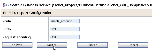
Enter the prefix and suffix for the output file to be received and click Next.
As shown in Figure 7-80, the Message Handling and Advanced Settings page is displayed.
Figure 7-80 Message Handling and Advanced Settings Page

Click Next.
The following Summary page is displayed, as shown in Figure 7-81.
Review all the information for your Business Service and click Save.
Perform the following steps to configure a Pipeline:
As shown in Figure 7-82, click the Edit Message Flow icon in the row of the Proxy Service you created.
The Edit Message Flow workspace area is displayed, as shown in Figure 7-83.
Figure 7-83 Edit Message Flow Workspace Area
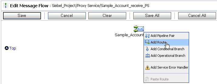
Click the displayed Proxy service icon and select Add Route from the menu.
The RouteNode1 icon is added below the Request Pipeline icon.
As shown in Figure 7-84, click the RouteNode1 icon and select Edit Route from the menu.
The Edit Stage Configuration workspace area is displayed, as shown in Figure 7-85.
Figure 7-85 Edit Stage Configuration Workspace Area
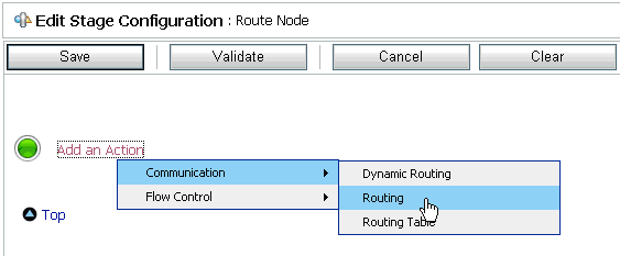
Click Add an Action, select Communication from the menu, and click Routing.
Figure 7-86 Edit Stage Configuration Page
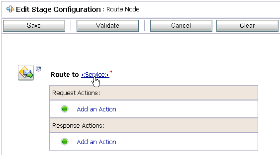
As shown in Figure 7-86, click <Service>.
The Select Service dialog is displayed, as shown in Figure 7-87.
Select a File type Business Service and click Submit.
As shown in Figure 7-88, you are returned to the Edit Stage Configuration workspace area.
Figure 7-88 Edit Stage Configuration Workspace Area
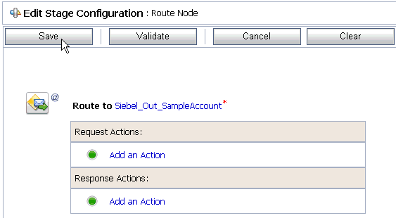
Click Save.
As shown in Figure 7-89, you are returned to the Edit Message Flow workspace area.
Figure 7-89 Edit Message Flow Workspace Area

Click Save.
Figure 7-90 Message Flow Updated Successfully Message

As shown in Figure 7-90, check if the success message is displayed and click Activate in the Change Center.
The Activate Session page is displayed, as shown in Figure 7-91.
Click Submit.
As shown in Figure 7-92, check if the View Configuration Changes page is displayed.
Figure 7-92 View Configuration Changes Page

Trigger an event from the Siebel system and check if the output is received in the configured output location.
This section describes how to configure outbound processing using Oracle Service Bus for BSE configurations.
Samples have been provided for this usecase scenario in the etc/sample folder in the Application Adapters installation.
This section includes the following topics:
Setting the Class Path for Application Explorer to Integrate With Oracle Service Bus
Publishing a WSDL From Application Explorer to Oracle Service Bus
Perform the following steps to start Oracle Service Bus and create project folders:
Start the Oracle WebLogic Server for the Oracle WebLogic Server domain that you have configured.
Open the Oracle Service Bus Console in a Web browser by entering the following URL:
http://hostname:port/sbconsole
Where hostname is the name of the machine where Oracle WebLogic Server is running and port is the port for the domain you are using. The port for the default domain is 7001.
The Oracle Service Bus Console logon page is displayed.
Log on to the Oracle Service Bus Console using a valid user name and password.
The Oracle Service Bus Console home page is displayed, as shown in Figure 7-93.
Figure 7-93 Oracle Service Bus Console Home Page

As shown in Figure 7-94, click Create in the Change Center area to start a new Oracle Service Bus session.
Click Project Explorer in the left pane, as shown in Figure 7-95.
The Project Explorer page is displayed, as shown in Figure 7-96.
Provide a valid name for the new project (for example, Siebel_Project) and click Add Project.
The new project is successfully created and listed in the left pane.
Click the new project node in the left pane.
The project page is displayed, as shown in Figure 7-97.
In the Enter New Folder Name field, type Business Service and click Add Folder.
In the Enter New Folder Name field, type Proxy Service and click Add Folder.
In the Enter New Folder Name field, type wsdls and click Add Folder.
The Business Service, Proxy Service, and wsdls folders are listed in the left pane below the new Siebel_Project node, as shown in Figure 7-98.
Figure 7-98 Business Service, Proxy Service, and wsdls Folders Listed Under Project Explorer

Click Activate in the Change Center.
The Activate Session page is displayed, as shown in Figure 7-99.
Click Submit.
Before starting and using Application Explorer to publish a WSDL directly to the Oracle Service Bus (OSB) Console (project/folder), OSB users must perform the following steps:
Open the command prompt window.
Navigate to the following directory:
<OSB_Home>\user_projects\domains\base_domain\bin
Execute setDomainEnv.cmd (Windows) or . ./setDomainEnv.sh (UNIX/Linux).
This command sets the class path for Application Explorer to access the Oracle WebLogic Server APIs to publish the WSDLs to the OSB Console.
Do not close the command prompt window.
Navigate to the following directory:
<OSB_Home>\3rdparty\ApplicationAdapters\tools\iwae\bin
Execute ae.bat (Windows) or iwae.sh (UNIX/Linux) to start Application Explorer.
You are now ready to publish WSDLs from Application Explorer to the OSB Console.
This section describes how to publish a WSDL from Application Explorer (BSE configuration) to Oracle Service Bus.
Start Application Explorer, connect to a BSE configuration, and connect to a Siebel target, as shown in Figure 7-100.
Figure 7-100 Create Web Service Option Selected from the Application Explorer
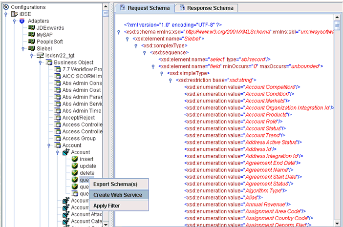
Expand the Business Object node and select the Account object.
Right-click the query method and select Create Web Service from the menu.
The Create Web Service dialog is displayed, as shown in Figure 7-101.
Enter a service name and click Next.
Click OK on the next dialog that is displayed.
Application Explorer switches the view to the Business Services node, and the new Web service appears in the left pane.
As shown in Figure 7-102, right-click the new Web service and select Export WSDL from the menu.
The Export WSDL dialog is displayed, as shown in Figure 7-103.
In the Name field, a default file name for the WSDL file is provided. You can accept the default or provide your own.
In the Location field, enter the location where you want to publish the WSDL document.
The location is composed of an Oracle Service Bus project name and optionally, one or more folder names. The project name and any folder names must be separated by a forward slash character “/”.
In the Host field, enter the name of the machine where Oracle WebLogic Server is running.
In the Port field, enter the port for the domain you are using.
In the User field, enter your username to access Oracle Service Bus.
In the Password field, enter your password to access Oracle Service Bus.
Click OK.
The WSDL is published to the location specified in the Export WSDL dialog and is now available for use with a Business Service or Proxy Service in Oracle Service Bus.
This section describes how to configure a File type Business Service using the Oracle Service Bus Console.
As shown in Figure 7-104, select the Business Service folder you created in the left pane.
In the right pane, select Business Service from the Create Resource menu.
The General Configuration page is displayed, as shown in Figure 7-105.
Provide a name for the Business Service and from the Service Type area select Messaging Service.
Click Next.
The Message Type Configuration page is displayed, as shown in Figure 7-106.
Figure 7-106 Message Type Configuration Page
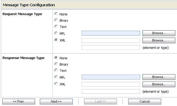
Select XML as the Request Message Type and None as the Response Message Type.
Click Next.
The Transport Configuration page is displayed, as shown in Figure 7-107.
Figure 7-107 Transport Configuration Page
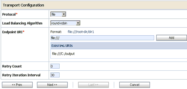
Select file from the Protocol list.
Enter the path to a destination folder on your file system in the Endpoint URI field and click Add.
Click Next.
The FILE Transport Configuration page is displayed, as shown in Figure 7-108.
Figure 7-108 FILE Transport Configuration Page

Enter the prefix and suffix for the output file to be received and click Next.
The Summary page is displayed, as shown in Figure 7-109.
Review all the information for your Business Service and click Save.
This section describes how to configure a WSDL type Business Service using the Oracle Service Bus Console.
As shown in Figure 7-110, select the Business Service folder you created in the left pane.
In the right pane, select Business Service from the Create Resource menu.
The General Configuration page is displayed, as shown in Figure 7-111.
Provide a name for the Business Service and from the Service Type area select WSDL Web Service.
Click Browse.
As shown in Figure 7-112, the Select a WSDL dialog is displayed.
Select a BSE WSDL that you published for OracleAS Adapter for Siebel using Application Explorer and click Submit.
The Select a WSDL Definition dialog is displayed, as shown in Figure 7-113.
Figure 7-113 Select a WSDL Definition Dialog
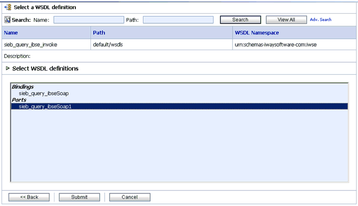
Select the WSDL definition under the Ports section and click Submit.
You are returned to the General Configuration page where the WSDL you selected is now available.
Click Next.
The Transport Configuration page is displayed, as shown in Figure 7-114.
Figure 7-114 Transport Configuration Page
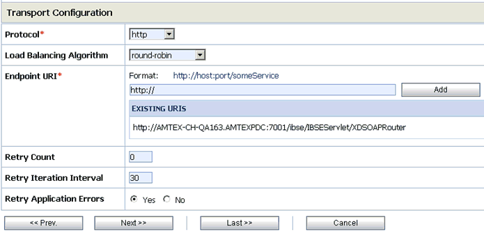
Leave the default values and click Next.
The HTTP Transport Configuration page is displayed, as shown in Figure 7-115.
Figure 7-115 HTTP Transport Configuration Page
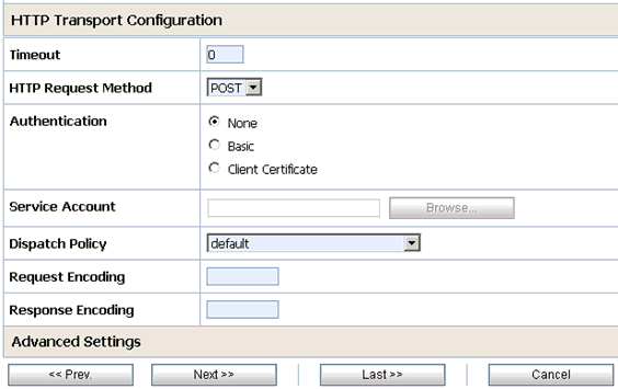
Leave the default values and click Next.
The SOAP Binding Configuration page is displayed, as shown in Figure 7-116.
Figure 7-116 SOAP Binding Configuration Page

Click Next.
The Message Content Handling page is displayed, as shown in Figure 7-117.
Figure 7-117 Message Content Handling Page

Click Next.
The Summary page is displayed, as shown in Figure 7-118.
Review all the information for your Business Service and click Save.
This section describes how to configure a Proxy Service using the Oracle Service Bus Console.
As shown in Figure 7-119, select the Proxy Service folder you created in the left pane.
In the right pane, select Proxy Service from the Create Resource menu.
The General Configuration page is displayed, as shown in Figure 7-120.
Provide a name for the Proxy Service and from the Service Type area select Any XML Service.
Click Next.
The Transport Configuration page is displayed, as shown in Figure 7-121.
Figure 7-121 Transport Configuration Page
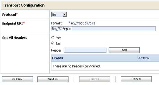
Select file from the Protocol list.
Enter the path to an input folder on your file system in the Endpoint URI field.
This is the folder where the XML input file will be copied during runtime.
Click Next.
The FILE Transport Configuration page is displayed, as shown in Figure 7-122.
Figure 7-122 FILE Transport Configuration Page
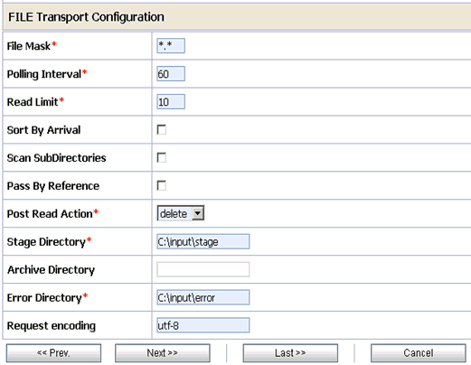
Provide any folder locations on your file system for the Stage Directory and Error Directory fields.
Click Next.
The Message Content Handling page is displayed, as shown in Figure 7-123.
Figure 7-123 Message Content Handling Page
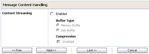
Click Next.
The Summary page is displayed, as shown in Figure 7-124.
Review all the information for your Proxy Service and click Save.
This section describes how to configure a Pipeline using the Oracle Service Bus Console.
As shown in Figure 7-125, click the Edit Message Flow icon in the row of the Proxy Service you created.
The Edit Message Flow workspace area is displayed.
As shown in Figure 7-126, click the Proxy Service icon and select Add Pipeline Pair from the menu, as shown in the following image.
Click the PipelinePairNode1 icon and select Add Route from the menu as shown in Figure 7-127.
As shown in Figure 7-127, click the RouteNode1 icon and select Edit Route from the menu.
As shown in Figure 7-128, click Add an Action, select Communication from the menu, and click Routing.
Figure 7-129 Edit Stage Configuration Workspace Area
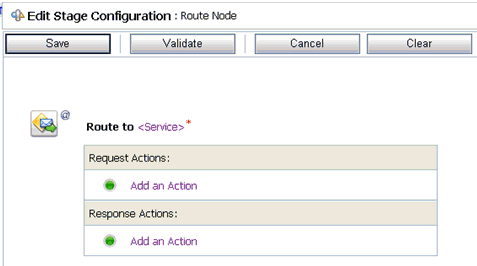
As shown in Figure 7-129, click <Service>.
The Select Service dialog is displayed, as shown in Figure 7-130.
Select a WSDL type Business Service and click Submit.
As shown in Figure 7-131, you are returned to the Edit Stage Configuration workspace area.
Figure 7-131 Edit Stage Configuration Workspace Area
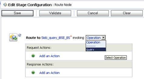
Select query as the operational attribute from the list.
Click Validate and then Save.
You are returned to the main Pipeline configuration area, as shown in Figure 7-132.
Click the Response Pipeline icon and select Add Stage from the menu.
The Stage1 icon is added below the Response Pipeline icon.
As shown in Figure 7-133, click the Stage1 icon and select Edit Stage from the menu.
The Edit Stage Configuration workspace area is displayed, as shown in Figure 7-134.
Figure 7-134 Edit Stage Configuration Workspace Area
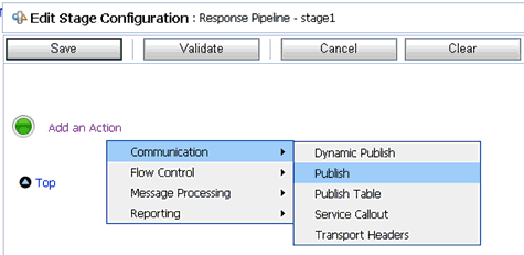
Click Add an Action, select Communication from the menu, and click Publish.
Figure 7-135 Edit Stage Configuration Workspace Area
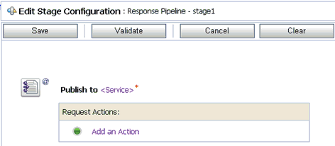
As shown in Figure 7-135, click <Service>.
The Select Service dialog is displayed, as shown in Figure 7-136.
Select a File type Business Service and click Submit.
You are returned to the Edit Stage Configuration workspace area.
Click Validate and then Save.
The completed Pipeline is displayed, as shown in Figure 7-137.
Click Save.
As shown in Figure 7-138, click Activate in the Change Center area to activate your changes in the Oracle Service Bus session.
As shown in Figure 7-139, copy and paste an input XML file in the input folder you have configured.
Figure 7-139 Input XML File Copied to the Configured Input Folder
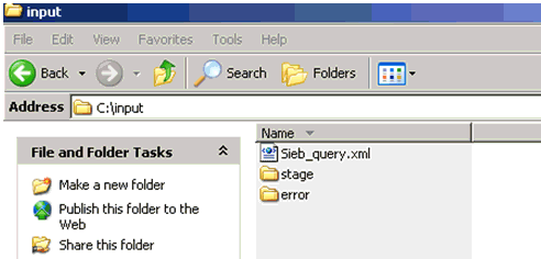
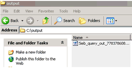
An output XML file is received in the destination folder, as shown in Figure 7-140.
Figure 7-140 Output XML File Received in the Destination Folder
