| Skip Navigation Links | |
| Exit Print View | |

|
Oracle Solaris Administration: Network Interfaces and Network Virtualization Oracle Solaris 11 Information Library |
| Skip Navigation Links | |
| Exit Print View | |

|
Oracle Solaris Administration: Network Interfaces and Network Virtualization Oracle Solaris 11 Information Library |
1. Overview of the Networking Stack
Network Configuration in This Oracle Solaris Release
The Network Stack in Oracle Solaris
Network Devices and Datalink Names
The Assignment of Generic Names to Datalinks
Customizing How Generic Link Names Are Assigned
Link Names in Upgraded Systems
Replacing Hardware-Based Link Names
Caution About Changing Link Names
3. NWAM Configuration and Administration (Overview)
4. NWAM Profile Configuration (Tasks)
5. NWAM Profile Administration (Tasks)
6. About the NWAM Graphical User Interface
Part II Datalink and Interface Configuration
7. Using Datalink and Interface Configuration Commands on Profiles
8. Datalink Configuration and Administration
9. Configuring an IP Interface
10. Configuring Wireless Interface Communications on Oracle Solaris
12. Administering Link Aggregations
16. Exchanging Network Connectivity Information With LLDP
Part III Network Virtualization and Resource Management
17. Introducing Network Virtualization and Resource Control (Overview)
18. Planning for Network Virtualization and Resource Control
19. Configuring Virtual Networks (Tasks)
20. Using Link Protection in Virtualized Environments
21. Managing Network Resources
The separation between network configuration and network hardware configuration introduces the same flexibility to other types of link configurations. For example, virtual local area networks (VLANs), link aggregations, and IP tunnels can be assigned administratively-chosen names and then configured by referring to those names. Other related tasks, such as performing dynamic reconfiguration (DR) to replace hardware devices, are also easier to perform because no further network reconfiguration is required, provided that the network configuration was not deleted.
The following figure shows the interrelationship among devices, link types, and their corresponding interfaces.
Note - In the figure, the datalinks are named according to specific functions that they perform in the system, such as video0 or sales2. The figure intends to highlight the flexibility with which you can name the datalinks. However, using the default neutral names such as net0 as supplied by the OS is sufficient and preferable.
The figure also provides a sample of how administratively chosen names can be used in the network setup;
VLANs are configured on the net0 link. These VLANs, in turn, are also assigned customized names, such as sales1 and sales2. The VLAN sales2's IP interface is plumbed and operational.
The device instances qfe0 and qfe2 are used to service video traffic. Accordingly, the corresponding links in the datalink layer are assigned the names subvideo0 and subvideo1. These two links are aggregated to host video feed. The link aggregation possesses its own customized name as well, video0.
Two interfaces (net0 and net1) with different underlying hardware (e1000g and qfe) are grouped together as an IPMP group (itops0) to host email traffic.
Note - Although IPMP interfaces are not links on the datalink layer, these interfaces, like the links, can also be assigned customized names. For more information about IPMP groups, see Chapter 14, Introducing IPMP.
Two interfaces have no underlying devices: the tunnel vpn1, which is configured for VPN connections and lo0 for IP loopback operations.
All of the link and interface configurations in this figure are independent of the configurations in the underlying hardware. For example, if the qfe card is replaced, the video0 interface configuration for video traffic remains and can later be applied to a replacement NIC.
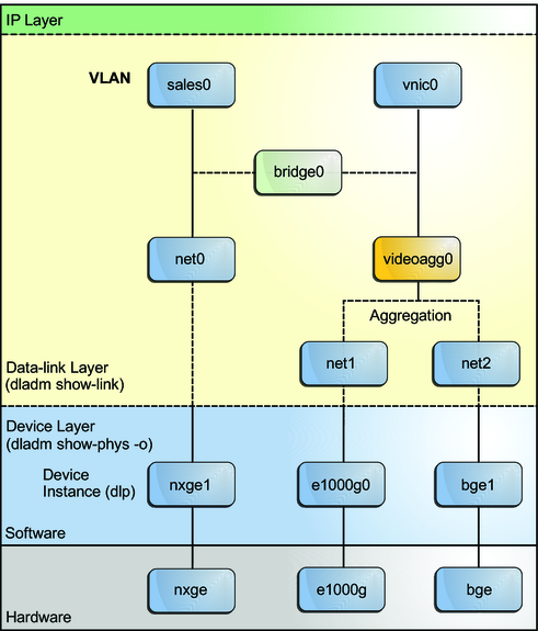
The following figure shows a bridge configuration. Two interfaces, net0 and videoagg0, are configured as a bridge, bridge0. Packets that are received on one are forwarded to the other. After bridge configuration, both interfaces can still be used to configure VLANs and IP interfaces.
Figure 1-3 Bridges in the Network Stack
