9 Administering and Monitoring an IaaS Cloud
This chapter describes the monitoring and administrative tasks that you can perform on the zones, virtual server pools, virtual servers and guest virtual machines within an IaaS Cloud. It includes the following sections:
9.1 Viewing the Infrastructure Cloud Home Page
The Cloud target is available out of the box and represents the entire virtualization infrastructure monitored by Enterprise Manager Cloud Control. You can view and monitor the various targets in the data center from the Infrastructure Cloud Home page. To view the Infrastructure Cloud Home page, follow these steps:
-
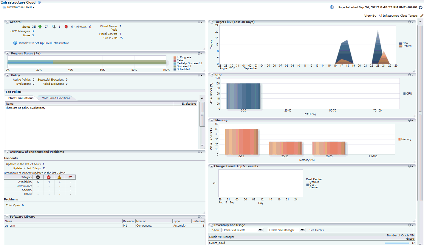
From the Enterprise menu, select Cloud, then select Oracle VM Infrastructure Home. The Infrastructure Cloud Home page shows the various targets such as zones, pools, and virtual servers, request status, policies, and so on. Click the video link to view a demo on setting up the cloud infrastructure.
The Infrastructure Cloud Home page shows the following details:
-
General: Shows the number of OVM Managers, zones, and servers, and guest virtual machines in the cloud and the status of each target. Select a link to drill down to the Members page.
-
Target Flux: Shows the number of targets (Guest VMs, Oracle VM Managers, Zones, server pools, virtual servers) created and deleted over the last 30 days.
-
Request Status: Shows the status of various requests and reservations. Click the graph to drill down to the Requests page.
-
CPU & Memory: Shows the CPU and memory utilization by the virtual servers in the data center.
-
Software Library: Shows the number of assemblies and templates available in the software library and how many have been deployed.
-
Policy: Shows the status of the various policies that have been defined for the cloud. It shows the number of corrective actions that were executed and whether they were successful. Click the graph to drill down to the Policy Home page.
-
Overview of Incidents and Problems: Shows the various incidents and policy violations that have occurred in the last 24 hours.
-
Charge Trend: Shows the charge back break-up data across the cloud. It lists the top 5 requests that have incurred the highest cost.
-
Inventory and Usage: Shows the inventory summaries for virtual servers, guest virtual machines, and assembly instances. Select an option from the Show drop down list to view the details. You can view the summary information in the context of different dimensions. For example, for Oracle VM Servers, you can view the number of virtual servers under each Oracle VM Manager, zone, virtual server pool, and so on.
Click on the bar charts to drill down multiple levels of inventory details. Click See Details to drill down to the Inventory and Usage Details page which provides detailed information on the selected target and associated inventory charts.
Before you can start monitoring a virtualization target, you must register the OVM Manager target. See Section 5.3, "Registering the Oracle VM Manager" for details.
9.2 Viewing the OVM Manager Home Page
The OVM Manager provides the interface to monitor zones, virtual servers, virtual server pools, and guest virtual machines. A zone is a set of virtual server pools. Each virtual server pool contains one or more virtual servers and guest virtual machines. A virtual server pool cannot belong to more than one zone. To view the OVM Manager Home page, follow these steps:
-
From the Enterprise menu, select Cloud, then select Oracle VM Infrastructure Home.
-
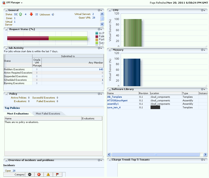
Click on an OVM Manager target from the left panel. The OVM Manager Home page shows the following details:
-
General: Shows the number of zones, and servers, and guest virtual machines under the OVM Manager and the status of each target. Click on a link to drill down to the Members page.
-
Request Status: Shows the status of all requests for this OVM Manager. Click on the graph to drill down to the All Requests page.
-
Job Activity: Shows the list of jobs started within the last 7 days.
-
Policy: Shows the status of all the policies that have been defined for the OVM Manager. It shows the number of corrective actions that were executed and whether they were successful.
-
Overview of Incidents and Problems: Shows all the incidents and problems reported on the OVM Manager and member targets.
-
Inventory and Usage: Shows the inventory summaries for virtual servers, guest virtual machines, and assembly instances. Select an option from the Show drop down list to view the details. You can view the summary information in the context of different dimensions. For example, for Oracle VM Servers, you can view the number of virtual servers under each Oracle VM Manager, zone, virtual server pool, and so on.
Click on the bar charts to drill down multiple levels of inventory details. Click See Details to drill down to the Inventory and Usage Details page which provides detailed information on the selected target and associated inventory charts.
-
CPU & Memory: Shows the CPU and memory utilization by the virtual servers under the OVM Manager.
-
Software Library: Shows the templates and assemblies that have been deployed.
-
Charge Trend: Top 5 Tenants: Shows the charge back break-up data across the OVM Manager. It lists the top 5 requests that have incurred the highest cost.
-
-
From the OVM Manager Home page, you can do the following:
-
Edit OVM Manager
-
Synchronize OVM Manager
-
Deregister OVM Manager
-
Create a Zone
-
Create a Virtual Server Pool
-
Discover a Virtual Server
-
Manage Unowned Virtual Server
-
Manage Networks
-
Manage Storage
-
Manage Storage Repository
-
Manage YUM Repository
-
Manage NTP Configurations
-
9.3 Viewing and Managing Members
You can view and manage members for one or more virtualization targets on this page.
-
From the Enterprise menu select Cloud, then select Oracle VM Infrastructure Home.
-
Right click on the Infrastructure Cloud menu, select Members, then select Show All.

-
The list of OVM Managers, Zones, Virtual Server Pools, Virtual Servers, and Guest Virtual Machines that can be managed from the Infrastructure Cloud appear.
-
You can:
-
Click on a target to drill down to its Home page.
-
Select a target and click on an option from the Actions menu. The actions you can perform vary based on the target you have selected.
-
Note:
You can view and manage the members under a OVM Manager target, zone, virtual server pool, or virtual server. From the Infrastructure Cloud Home page, select the appropriate target (such as an OVM Manager, zone, virtual server pool, or virtual server) from the left panel. From the Infrastructure Cloud menu, select Members, then select Show All. The Members page for the selected target appears and you can perform various administrative activities on these targets.9.4 Managing Zones
This section describes the following:
9.4.1 Viewing the Zone Home Page
A zone is a logical grouping of resources like servers and storage entities. It is a logical entity used to organize the guest virtual machines exposed to the self service application user. Zones have metrics that show the aggregate utilization of the zone. To view the Zone Home page, follow these steps:
-
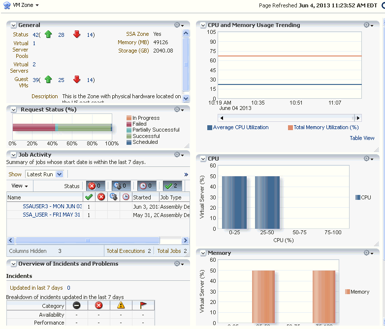
From the Enterprise menu select Cloud, then select Oracle VM Infrastructure Home. In the left panel, click on the zone to be viewed. the The following details are displayed:
-
-
General: Shows the number of virtual servers, virtual server pools, and guest virtual machines under this zone and the status of each target. Click on a link to drill down to the Members page.
-
Job Activity: Shows the list of jobs started within the last 7 days.
-
Overview of Incidents and Problems: Shows all the incidents and problems reported on the OVM Manager and member targets.
-
CPU and Memory Usage Trending: Shows the average CPU and memory utilization over the last 30 days.
-
CPU and Memory: Shows the CPU and memory utilization by the virtual servers and guest virtual machines in this zone.
-
9.4.2 Creating or Editing a Zone
A zone is a collection of virtual server pools which share storage. Follow these steps to create a zone:
-
From the Enterprise menu, select Cloud, then select Oracle VM Infrastructure Home.
-
Select the OVM Manager target for which the zone is to be created, and click Create Zone from the OVM Manager menu.
-
In the Create Zone page, specify the zone name and description.
-
Indicate if this zone will be used by the self service users by checking the Infrastructure Cloud Self Service Zone check box.
-
Click Add in the Virtual Server Pool section to add one or more virtual server pools. See Section 5.14, "Creating a Virtual Server Pool" for details.
-
Click Create Zone and click OK. After the successful completion of this job, the virtual server pools appear in the newly created zone on the Virtualization Central Home page.
Note:
To edit an existing zone, follow these steps:-
From the Enterprise menu, select Cloud, then select Oracle VM Infrastructure Home.
-
Select a zone target from the left panel.
-
From the Zone menu, select Target Setup, then select Edit VM Zone.
9.4.3 Deleting a Zone
To delete a zone, follow these steps:
-
From the Enterprise menu, select Cloud, then select Oracle VM Infrastructure Home.
-
Click on a zone target from the left panel to navigate to the Zone Home page. From the Zone menu, select Target Setup, then select Delete. A confirmation message appears.
-
Click OK to delete the zone. Any virtual server pools that are members of this zone will now be moved under the OVM Manager target.
Note:
If Chargeback has been enabled for the zone (or virtual server pools / guest virtual machines within the zone) being deleted, the metric data is automatically disabled when the target is deleted.
9.4.4 Deleting a Zone from Enterprise Manager
To delete a zone from Enterprise Manager, follow these steps:
-
From the Enterprise menu, select Cloud, then select Oracle VM Infrastructure Home.
-
Click on a zone target from the left panel to navigate to the Zone Home page. From the Zone menu, select Target Setup, then select Delete from Enterprise Manager. A confirmation message appears.
-
Click OK to delete the zone. The zone and the associated targets under this zone will be removed from Enterprise Manager. After synchronization, these targets will be added back to Enterprise Manager.
Note:
If Chargeback has been enabled for the zone (or virtual server pools / guest virtual machines within the zone) being deleted, the metric data is automatically disabled when the target is deleted.
9.5 Viewing the Virtual Server Pool Home Page
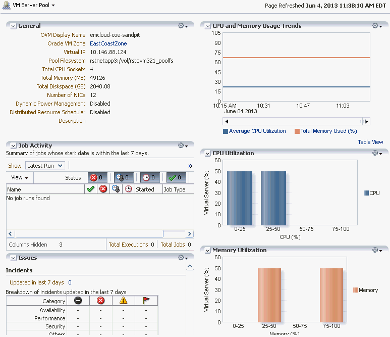
A virtual server pool is logically an autonomous region that contains one, or more virtual servers. A virtual server pool may or may not belong to a zone. However, it can belong to only one zone at a time. The following details are displayed:
-
General: Shows details of the virtual server pool such as the zone to which it belongs, the number of CPUs, memory and storage, and number of NICs.
-
Job Activity: Shows the list of jobs started within the last 7 days.
-
Issues: Shows all the incidents and problems reported on the virtual server pool and member targets.
-
CPU and Memory Usage Trends: Shows the average CPU and memory utilization by the virtual servers in the zone over the last 30 days.
-
CPU and Memory Utilization: These charts show the CPU and memory utilization by all the virtual servers in the server pool.
9.6 Managing Virtual Servers
This section describes the following:
9.6.1 Virtual Server Home Page
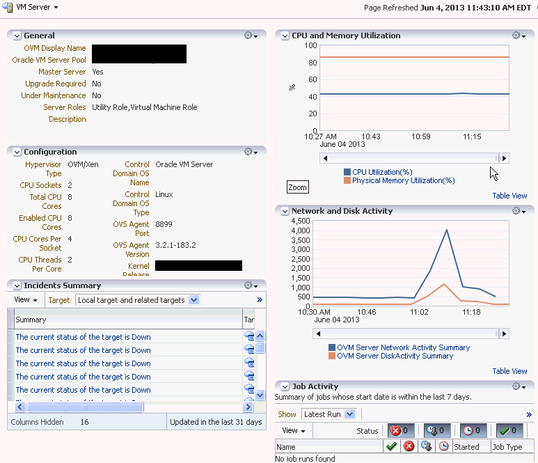
A virtual server is a generic term used to describe a physical machine which has virtualization software (hypervisor) running on it. A virtual server can belong to one and only one virtual server pool at a time. Guest virtual machines and resources are also associated with the server pools.
The following regions are displayed:
-
General: Shows details of the virtual server such as the virtual server pool it belongs to, whether the server needs to be upgraded, if it is under maintenance, and so on.
-
Job Activity: Shows the list of jobs started within the last 7 days.
-
Configuration: The virtual server configuration such as number of enabled CPU cores and processors, memory, diskspace, OVS Agent Port, and so on.
-
Network and Disk Activity: The network and disk activity of the virtual server.
Note:
If you are using Oracle VM Manager 3.2 4, the Disk Activity is not shown in the graph. -
CPU and Memory Utilization: The CPU and memory utilization of the virtual server.
-
Incident Summary: This region shows a list of incidents and problems reported on all the Guest VMs and related targets.
9.6.2 Editing a Virtual Server
To edit a virtual server, follow these steps:
-
From the Enterprise menu, select Cloud, then select Oracle VM Infrastructure Home.
-
In the left panel, select the virtual sever that is to be edited. The Virtual Server Home page appears.
-
From the Virtual Server menu, select Target Setup, then select Edit VM Server. You can modify the description of the virtual server and the following fields:
-
Configure IPMI: Select the Enable Server IPMI checkbox to enable the Intelligent Platform Management Interface (IPMI). Selecting this option allows you to remotely power off a virtual server and send a wake on lan message to power on a virtual server without having to physically press the power button. If this checkbox is selected, you must enter the user name, password, and IP address of the IPMI.
-
Server Role: A server can be designated to perform utility or virtual machine functions by specifying the role which can be:
-
Utility Role: Servers with this role are used to perform non-virtual machine operations such as cloning, importing templates, creating repository, deleting assemblies and so on.
-
Virtual Machine Role: Servers with this role are used to run virtual machines. This role cannot be deselected if the virtual server already contains Guest VMs.
-
-
-
Click OK to confirm the changes.
9.6.3 Upgrading a Virtual Server
After the YUM Repository has been set up (see Section 5.17.1, "Configuring the YUM Repository"), you must upgrade the virtual server to ensure that it has the latest updates. The virtual server must be in maintenance mode if it is to be upgraded.
To upgrade the virtual server, follow these steps:
-
From the Enterprise menu, select Cloud, then select Oracle VM Infrastructure Home.
-
Right click on a VM Server from the left panel and select Upgrade.
-
After the virtual server has been upgraded, the virtual server will be restarted.
9.6.4 Starting and Stopping a Virtual Server
You can start a virtual server that is in a Stopped state. To start a virtual server, follow these steps:
Note:
Before you start the virtual server, you must ensure that the IPMI has been configured. See Section 9.6.2, "Editing a Virtual Server".-
From the Enterprise menu, select Cloud, then select Oracle VM Infrastructure Home.
-
Right click on a virtual server target in the left panel and select Start. A confirmation message appears.
-
Click OK to start the virtual server.
You can stop a virtual server that is Up. To stop a virtual server, follow these steps:
-
Login to Enterprise Manager Cloud Control.
-
From the Enterprise menu, select Cloud, then select Oracle VM Infrastructure Home.
-
Right click on a virtual server target in the left panel and select Stop. A confirmation message appears.
-
Click OK to stop the virtual server.
9.6.5 Performing Maintenance on the Virtual Server
You can place a virtual server in maintenance mode to perform hardware and software maintenance. When a virtual server is placed in maintenance mode, any virtual machines running on the virtual server are automatically migrated to other virtual servers in the server pool, if they are available, otherwise they are stopped. The server pool roles being performed by the virtual server are also moved to other virtual servers in the server pool, if available.To place an Oracle VM Server into maintenance mode:
-
From the Enterprise menu, select Cloud, then select Oracle VM Infrastructure Home.
-
Select a virtual server target from left panel.
-
Right click on a virtual server target from the left panel and select the Start Maintenance. The virtual server target is placed in blackout mode during maintenance.
When you have finished performing maintenance, click Stop Maintenance for it to rejoin the server pool.
9.7 Managing Guest Virtual Machines
This section describes the following:
9.7.1 Creating a Guest Virtual Machine
A guest virtual machine runs on a virtual server. You can create a guest virtual machine by using one of the following methods:
-
Assemblies
-
Templates
-
Installation Media (ISO or PXE)
For more details on creating a Guest VMs, see Section 9.8, "Deploying Guest Virtual Machines".
Before you create a guest virtual machine, you must have:
-
Discovered a virtual server.
-
Created a virtual server pool.
-
Created the necessary components in the Software Library
-
Deployed assemblies, templates, ISO images, or PXEs for creating virtual machines based on these.
9.7.2 Guest Virtual Machine Home Page
A guest virtual machine is the container running on top of a virtual server. Multiple guest virtual machines can run on a single virtual server. The following regions are displayed:
-
General: Shows details of the guest virtual machine such as the virtual server pool, and virtual server it belongs to, and a description.
-
Networks: Displays the network configuration for the guest virtual machine.
-
CPU and Memory Utilization: The CPU and memory utilization of the guest virtual machine.
-
Networks and Network Activity: The networks in the guest virtual machine and the network throughput of the guest virtual machine.
-
Configuration: The virtual server configuration such as number of virtual CPUs, CPU priority, allocated storage and memory, whether it is HA enabled, and the domain type.
-
Job Activity: Shows the list of jobs started within the last 7 days.
-
Incidents Summary: Shows the various alerts and policy violations that have occurred in the last 31 days.
From the Guest Virtual Machine Home page, you can do the following:
-
Edit a Guest VM
-
Migrate a Guest VM
-
Clone a Guest VM
-
Start and Stop
-
Reboot, Restart, Suspend, and Resume
9.7.3 Migrating a Guest Virtual Machine
To migrate one or more guest virtual machines, do the following
-
From the Enterprise menu, select Cloud, then select Oracle VM Infrastructure Home.
-
From the Infrastructure Cloud menu, select Members, then select Show All.
-
Expand the list of targets displayed and select one or more guest virtual machines from the list. From the Actions menu, select Guest VMs, then select Migrate. The Migrate page appears. You can select the following:
-
Running Guest VMs
-
Stopped / Suspended Guest VMs.
-
-
Select one or more Guest VMs from these regions, and click Submit.
Note:
For running Guest VMs, the virtual server to which the guest virtual machine is to be migrated is auto selected by default. For stopped or suspended Guest VMs, the target server can be modified if required.
9.7.4 Starting and Shutting Down a Guest Virtual Machine
After a guest virtual machine has been created, you can start it or shut it down. When a guest virtual machine is running, you can pause or suspend it temporarily:
9.7.4.1 Starting a Guest Virtual Machine
When a Guest VM has not been used for a while, it may be shut down to release system resources. To use the Guest VM, you must start it:
Prerequisites
The guest virtual machine must be Down.
-
From the Enterprise menu, select Cloud, then select Oracle VM Infrastructure Home.
-
Select the guest virtual machine target from the left panel.
-
Click Start from the guest virtual machine menu.
9.7.4.2 Restarting a Guest Virtual Machine
You may need to reboot or restart a virtual machine if operating system updates require you to restart the virtual machine, for example Microsoft Windows updates. To reboot a guest virtual machine:
Prerequisites
The guest virtual machine must be Up.
-
From the Enterprise menu, select Cloud, then select Oracle VM Infrastructure Home.
-
Right click on a guest virtual machine target from the left panel and click Restart.
9.7.4.3 Stopping a Guest Virtual Machine
You may need to stop a Guest VM that is not being used to release system resources.
Prerequisites
The guest virtual machine must be Up.
To stop a guest virtual machine:
-
From the Enterprise menu, select Cloud, then select Oracle VM Infrastructure Home.
-
Right click on a guest virtual machine target from the left panel and click Stop.
9.7.4.4 Killing a Guest Virtual Machine
Killing a virtual machine is equivalent to performing a power off of a virtual machine, similar to unplugging the power cable from a physical machine. This is not the recommended method of shutting down a virtual machine, but may be used if the Stop command fails to shut down the virtual machine.
To kill a guest virtual machine:
-
From the Enterprise menu, select Cloud, then select Oracle VM Infrastructure Home.
-
Right click on a guest virtual machine target from the left panel and click Kill.
9.7.5 Cloning a Guest Virtual Machine
-
At least one virtual machine must exist and be in a state appropriate for cloning to proceed.
-
You can clone a guest virtual machine to create one or more new virtual machines in the same server pool.
Note:
If you are using the Enterprise Manager for Oracle Virtualization 12.1.0.3 (listed as Oracle Virtualization in Self Update) plug-in or above, you can clone running guest virtual machines if the virtual disks associated with them are thin cloneable.To clone a guest virtual machine, follow these steps:
-
From the Enterprise menu, select Cloud, then select Oracle VM Infrastructure Home.
-
Select a guest virtual machine target from the left panel.
-
Click Clone from the guest virtual machine menu.
-
In the Select Target and Source page, specify the Request Name.
-
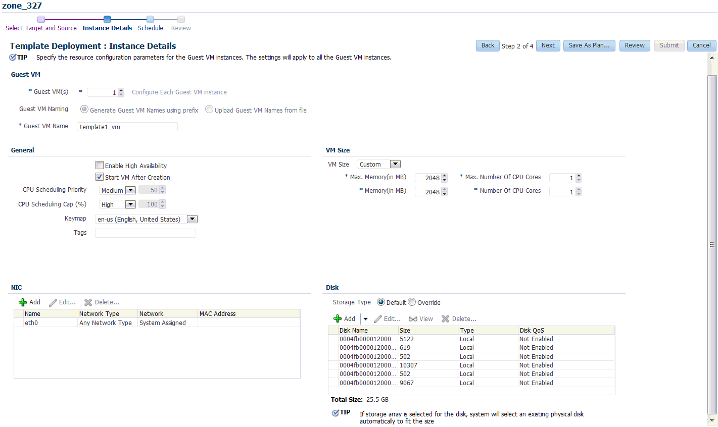
In the Deployment Configuration page, you can modify the following:
-
Guest VM:
-
Number of Guest VMs: The number of guest virtual machine instances being cloned.
-
Guest VM Naming: Indicates whether the guest virtual machine names are to be automatically generated or if the names will be uploaded from a file.
-
Guest VM Name: Enter a name of the guest virtual machine being cloned. The guest virtual machine name cannot contain any special characters.
-
-
General:
-
Enable High Availability / Start VM After Creation: Select the Enable High Availability and Start VM After Creation checkboxes to restart the guest virtual machine automatically after any outage.
-
CPU Scheduling Priority: Set the Priority of the virtual machine. You can select a high, medium, low, or custom priority for the virtual CPUs.
-
CPU Scheduling CAP: This parameter defines the percentage to which the virtual CPUs can receive scheduled time. You can select a high, medium, low, or a custom percentage of scheduled time for the virtual CPUs.
-
Keymap: The keyboard mapping that will be used by the guest virtual machine being cloned.
-
Tags: Specify one or more comma separated tags. These tags are used to logical group the virtual machines and can be used to search for one or more virtual machines that meet a certain criteria.
-
-
VM Size
-
VM Size: The amount of memory to be allocated to the guest virtual machine. The virtual server should have sufficient memory to run the guest virtual machine. Otherwise, the guest virtual machine will be created, but will not be started. The size of the guest virtual machine (memory and CPU values).
-
Memory: Specify the memory allocated to guest virtual machine. For a running guest virtual machine, this can be increased up to the Max Memory.
-
CPU Cores: Specify the number of virtual CPUs for the guest virtual machine. For a running guest virtual machine, this can be increased upto the Max virtual CPU.
-
-
Disk Configuration: You can configure the storage type to specify the location of the disks of the new cloned Guest VM. You can use the Default type as specified by the server pool or select Override. If you select Override, you must specify the Storage QoS and click the Search icon in the Storage field to specify the Storage Type. In the Storage Type window, specify the following:
-
Clone Target Type: This can be Repository or Storage Array.
-
Clone Target: If you select Repository, select the storage location where the disk is to be created. If you select Storage Array, specify the type, which can be SAN or ISCSI storage server.
-
Clone Type: This can be Sparse or Non-Sparse Copy. A sparse copy is a disk image file of a physical disk, taking up only the amount of space actually in use; not the full specified disk size. A non-sparse copy is a disk image file of a physical disk, taking up the space equivalent to the full specified disk size, including empty blocks.
-
-
Apart from specifying the storage type, you can also add new disks for the Guest VM to be cloned. Click Add New Disk to create a new disk in repositories and connect it to the target Guest VM. Click Attach Disk to provide the existing disk in the repositories and connect it to the Guest VM.
-
-
Click Next to continue.
-
On the Schedule page, specify whether the guest virtual machine is to be cloned immediately or later. Click Next.
-
On the Review page, review the configuration details and click Submit to run the cloning procedure.
9.7.6 Editing a Guest Virtual Machine
Note:
-
If you edit a guest virtual machine that is Up, you cannot modify the server size, storage and network fields. To edit these values, you must stop or halt the guest virtual machine.
-
You can create a new disk for a guest virtual machine which is Down, if Oracle VM Manager 3.1.1 and Enterprise Manager for Oracle Virtualization 12.1.0.2 plug-in have been installed. In other cases, existing disks are attached to the guest virtual machines.
To modify the configuration of a guest virtual machine, follow these steps:
-
From the Enterprise menu, select Cloud, then select Oracle VM Infrastructure Home.
-
Select a guest virtual machine target from the left panel. From the Guest VM menu, select Target Setup, then select Edit VM Guest. The Guest VM Configuration page appears.
-
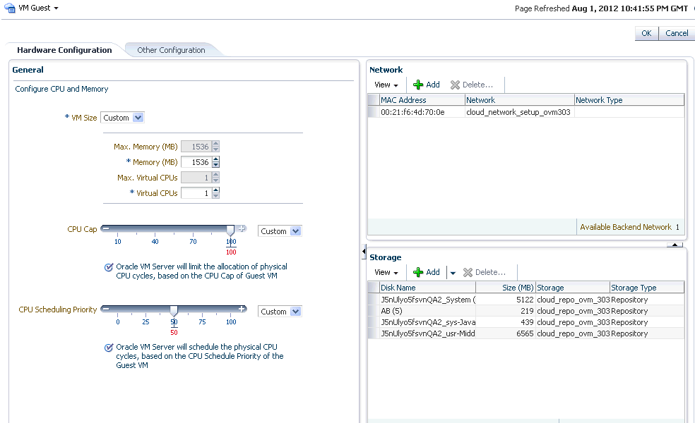
In the Hardware Configuration page, you can modify the following details:
-
General:
-
VM Size: The amount of memory to be allocated to the guest virtual machine. The virtual server should have sufficient memory to run the guest virtual machine. Otherwise, the guest virtual machine will be created, but will not be started. The size of the guest virtual machine (memory and CPU values).
-
Memory: Specify the memory allocated to guest virtual machine. For a running guest virtual machine, this can be increased upto the Max Memory.
-
CPU Cores: Specify the number of virtual CPUs for the guest virtual machine. For a running guest virtual machine, this can be increased upto the Max virtual CPU.
-
CPU Scheduling Priority: Set the Priority of the virtual machine. You can select a high, medium, low, or custom priority for the virtual CPUs.
-
CPU Scheduling CAP: This parameter defines the percentage to which the virtual CPUs can receive scheduled time. You can select a high, medium, low, or a custom percentage of scheduled time for the virtual CPUs.
-
-
Network: You can add delete virtual network interfaces. For more details, see Section 5.7, "Setting Up Networks".
-
Storage: Select the desired storage configuration of your virtual machine, such as virtual disks and ISO file.
-
-
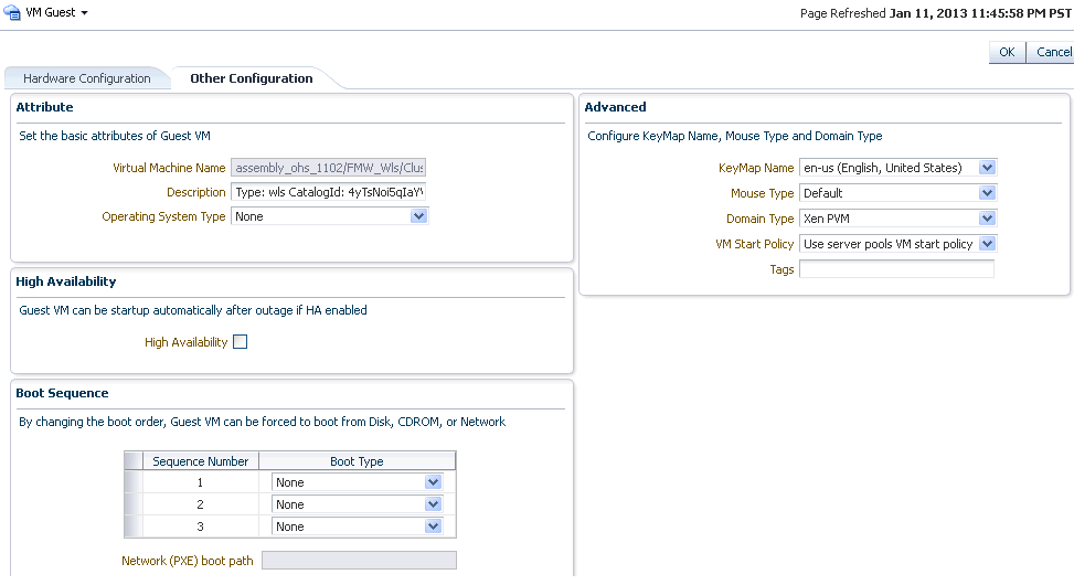
Click the Other Configuration tab.
-
Attribute: You can set the basic attributes of the guest virtual machine such as the description and the type of operating system to be used.
-
High Availability: If the High Availability checkbox is selected, the guest virtual machine will automatically restart after any outage.
-
Boot Sequence: Specify the boot sequence for the guest virtual machine. This is the boot order for the guest virtual machine and indicates if the guest virtual machine is forced to boot from disk, CDROM, or network.
-
Advanced:
-
Keymap Name: The name of the keyboard mapping that will be used by the guest virtual machine.
-
Mouse Type: The mouse type to be used for the guest virtual machine. This can be Default, PS2 Mouse, USB Mouse, or USB Tablet.
-
Domain Type: The domain type of the virtual machine. This can be:
Xen HVM: Hardware virtualization, or fully virtualized. When you select this option you must supply an ISO file in a repository (in the Create Storage step of the wizard) from which to create the virtual machine.
Xen HVM, PV Drivers: Identical to Xen HVM, but with additional paravirtualized drivers for improved performance of the virtual machine. This Domain Type is used to run Microsoft Windows guest operating systems with an acceptable performance level.
Xen PVM: Enables you to select a location for the mounted ISO file from which to create the virtual machine. Before you create the virtual machine using the paravirtualized method, mount the ISO file on an NFS share, or HTTP or FTP server. You supply the location of the mounted ISO file in the Network Boot Path field in the Boot Options step of the wizard.
OVM/SPARC: This domain type should be selected if the server pool and hypervisors use Oracle VM Server for SPARC as the hypervisor instead of Oracle VM Server for x86.
Unknown: This hypervisor should be selected if the domain type is unknown.
-
-
VM Start Policy: Select the policy to be used to start the virtual machines. You can choose:
Start on Best Server: The best server in the server pool is used to start the virtual machine.
Start on Current Server: The virtual machine will be started on the same server on which it was created.
-
Tags: Specify one or more comma separated tags. These tags are used to logical group the virtual machines and can be used to search for one or more virtual machines that meet a certain criteria.
-
9.7.7 Saving a Guest Virtual Machine as a Template
You can save a guest virtual machine as a template and use the template for provisioning guest virtual machines.
To save a guest virtual machine as a template, follow these steps:
-
From the Enterprise menu, select Cloud, then select Oracle VM Infrastructure Home.
-
Select a Guest VM target from the left panel. From the Guest VM menu, select Target Setup, then select Save Guest VM as a Template. The Save Guest VM as Template: Select Target and Source page appears.
-
The name of the guest virtual machine target that is to be saved as template is displayed.
-
In the Target Repository field, select the repository on which the guest virtual machine template is to be stored.
-
Specify a name for the template and click Next.
-
In the Save Guest VM as Template: Deployment Configuration page, you can modify the following details:
-
General Configuration:
-
Memory and No. of CPU Cores: Specify the Memory and No of CPU Cores (virtual CPUs) for the virtual machine. The number of processors is expressed in number of physical CPU cores, and is limited to 32. The memory and the number of processors that you can select is limited to the properties of the Virtual Machine Server. If you do not select a Virtual Machine Server however, you can set your desired value. You can modify the Max Virtual CPUs and Max Memory fields without restarting the Guest VM.
-
CPU Scheduling Priority: Set the Priority of the virtual machine. You can select a high, medium, low, or custom priority for the virtual CPUs.
-
CPU Scheduling CAP: This parameter defines the percentage to which the virtual CPUs can receive scheduled time. You can select a high, medium, low, or a custom percentage of scheduled time for the virtual CPUs.
-
Storage: Select the desired storage configuration of your virtual machine, such as virtual disks and ISO file.
-
Tags: Specify one or more comma separated tags. These tags are used to logical group the virtual machines and can be used to search for one or more virtual machines that meet a certain criteria.
-
-
Disk: Specify the storage type. You can use the Default type as specified by the server pool or select Override. If you select Override, you must specify the Storage QoS and click the Search icon in the Storage field to specify the Storage Type. In the Storage Type window, specify the following:
-
Clone Target Type: This can be Repository or Storage Array.
-
Clone Target: If you select Repository, select the storage location where the disk is to be created. If you select Storage Array, specify the type, which can be SAN or ISCSI storage server.
-
Clone Type: This can be Sparse or Non-Sparse Copy. A sparse copy is a disk image file of a physical disk, taking up only the amount of space actually in use; not the full specified disk size. A non-sparse copy is a disk image file of a physical disk, taking up the space equivalent to the full specified disk size, including empty blocks.
-
-
9.7.8 Deleting a Guest Virtual Machine
To delete a guest virtual machine, follow these steps:
-
From the Enterprise menu, select Cloud, then select Infrastructure Home.
-
Click on a guest virtual machine target from the left panel to navigate to the Guest VM Home page. From the Guest VM menu, select Target Setup, then select Delete. A confirmation message appears.
-
Click OK to delete the guest virtual machine. The guest virtual machine must be down before it can be deleted. This option deletes the guest virtual machine permanently from Oracle VM Manager.
9.7.9 Deleting a Guest Virtual Machine Only From Enterprise Manager
To delete a guest virtual machine only from Enterprise Manager, follow these steps:
-
From the Enterprise menu, select Cloud, then select Infrastructure Home.
-
Click on a guest virtual machine target from the left panel to navigate to the Guest VM Home page. From the Guest VM menu, select Target Setup, then select Delete from Enterprise Manager. A confirmation message appears.
-
Click OK to delete the guest virtual machine from the Enterprise Manager repository. This option does not delete the guest virtual machine from the Oracle VM Manager. You can use the Synchronize operation to restore the target to the Enterprise Manager repository. See Section 5.4, "Synchronizing the Oracle VM Manager Targets".
To permanently delete the guest virtual machine from the Enterprise Manager repository and the Oracle VM Manager, see Section 9.7.8, "Deleting a Guest Virtual Machine".
9.8 Deploying Guest Virtual Machines
This section describes the various options that can be used to deploy guest virtual machines. It contains the following sections:
-
Provisioning Guest Virtual Machines Using Oracle Virtual Assemblies (OVA)
-
Provisioning a Guest Virtual Machine Using Oracle VM Templates
9.8.1 Getting Started
This section helps you get started by providing an overview of the steps involved in provisioning virtualized systems. Consider this section to be a documentation map to understand the sequence of actions you must perform to successfully provision virtualized systems. Click the reference links provided against the steps to reach the relevant sections that provide more information.
Table 9-1 Getting Started with Oracle VM Provisioning
| Step | Description | Reference Link |
|---|---|---|
|
Step 1 |
Understanding the Deployment Options Understand the deployment plans offered by Enterprise Manager for deploying virtualization systems. |
To learn about the deployment options, see Section 9.8.2, "Deployment Options". |
|
Step 2 |
Meeting the Prerequisites Before you run the Deployment Procedure, you must meet the prerequisites, such as setting up the provisioning environment, applying mandatory patches, and creating the Software Library components. |
To learn about the prerequisites for provisioning guest virtual machines, see Section 9.8.3, "Prerequisites". |
|
Step 3 |
Selecting the Use Case This section covers a few use cases for the provisioning of guest virtual machines. Select the use case that best matches your requirements. |
To provision a guest virtual machine using:
|
9.8.2 Deployment Options
Enterprise Manager provides the following deployment options for provisioning guest virtual machines:
-
Virtual Machine Provisioning Using Assembly: Creates new guest virtual machines using an assembly component.
-
Virtual Machine Provisioning Using Template: Creates new guest virtual machines using a template component.
-
Virtual Machine Provisioning Using ISO: Creates a new guest virtual machine using an ISO image.
-
Virtual Machine Provisioning Using PXE: Creates a new guest virtual machine using Preboot Execution Environment. The new guest virtual machines will be PXE-booted and they will get provisioned by way of networks.
-
Cloning a Virtual Machine: Clones a guest virtual machine to one or more guest virtual machines.
9.8.3 Prerequisites
Before you run any deployment procedures, meet the infrastructure requirements described in this section.
-
Mandatory Infrastructure Requirements as defined in the Enterprise Manager Lifecycle Administrator's Guide.
-
Optional Infrastructure Requirements as defined in the Enterprise Manager Lifecycle Administrator's Guide.
-
The assembly, template, or the ISO image to be deployed must be present as a Software Library component, or at an external HTTP or NFS location, or imported to the server pool shared location.
9.8.3.1 Creating and Storing Virtualization Components in the Software Library
This section describes the procedure to create the virtualization components in the Software Library. It includes the following:
9.8.3.1.1 Creating an Assembly Component
An assembly is a collection of virtual machine instances. When an assembly is deployed, a group of virtual machines or an assembly instance is created.
-
The Assembly Binary, a file with a
.ovaextension must be present on the Management Agent or on an externalhttp/ftp/nfslocation.
Follow this process to create a new assembly component:
-
From the Enterprise menu, select Provisioning and Patching, then select Software Library.
-
Select a folder on the Software Library page. From the Actions menu, select Create Entity, then select Virtualization. You can also right click on a folder and select the virtualization option from the context menu.
-
From the Create Entity: Virtualization pop-up window, choose Assembly from the Select Subtype drop down list.
-
In the Create Assembly: Describe page, enter the following details:
-
Name and description of the assembly.
-
In the Attachments section, click Add to attach any files relevant to the entity. Ensure that the file size is less than 2 MB.
-
In the Notes section, include information related to the entity like changes being made to the entity or modification history that you want to track and click Add.
-
-
Click Next to continue. In the Create Assembly: Upload Files page, select one or more files to be associated with the assembly. You can either:
-
Upload Files: You can upload files from a storage location in the Software Library. For Software Library to become usable, at least one upload file location must be configured. Select the Upload Files option. In the Specify Destination section, click the Browse button in the Upload Location field. Two storage options are supported:
-
OMS Shared File System: An OMS Shared File System location is required to be shared (or mounted) across all the Oracle Management Server (OMS) hosts. This option is ideal for UNIX systems.
For single OMS environments, you can configure the Software Library either on the host where the OMS is running or in a shared location, so that it is accessible to all the OMS hosts. For multiple OMS environments, Oracle recommends that you configure the Software Library in a shared location so that the storage is accessible through NFS mount points to all Oracle Management Servers in the environment
-
OMS Agent File System: An OMS Agent File System location is a location that is accessible to one of the OMS host's Agent. This option is ideal for OMS installed on Windows hosts. By selecting this option for uploading files, you can avoid sharing a location between all participating OMS hosts.
Credentials must be set before using an OMS Shared File System or OMS Agent File System. For an OMS Shared File System, normal host credential must be set before configuring a storage location. However, for OMS Agent File System location configuration, a credential (preferred or named) has to be specified.
-
-
Refer Files: Select this option if you want to use an external file location where the software library files are staged. Referenced File Locations support three storage options:
-
HTTP: An HTTP storage location represents a base URL which acts as the source of files that can be referenced. For example, the base URL
http://my.files.com/scriptscould be configured as an HTTP location for sourcing files such ashttp://my.files.com/scripts/perl/installMyDB.plorhttp://my.files.com/scripts/linux/stopMyDB.sh. -
Agent: A storage location is similar to the OMS Agent File System option, but can be any host monitored by an Management Agent. The Management Agent can be configured to serve the files located on that host. For example, the directory
/u01/binarieson the Enterprise Manager Hostmy.em.file.servercould be configured as an Agent location for sourcing files such as/u01/binaries/rpms/myCustomDB.rpmor/u01/binaries/templates/myTemplate.tar.gz -
NFS: An NFS storage location represents an exported file system directory on a server. The server need not be an Enterprise Manager host target. For example, the directory
/exported/scriptsis exported on server my.file.server could be configured as an NFS location for sourcing files such as/exported/scripts/generic/installMyDB.plor/exported/scripts/linux/stopMyDB.shonce mounted on a target host file system.
These locations require a named credential to be associated which will be used to access the files from the base location on the host through the Management Agent.
-
-
Specify Source: You can add additional file storage locations.
-
To add a HTTP location that can be accessed through a HTTP URL, select HTTP from the Storage Type list and click Add. In the Add HTTP Location dialog box, enter a unique name and a HTTP location for the storage that you want to reference, and click OK. A new entry for the storage location is created, with details like Name, Location, and Status.
-
To add a Management Agent location that has read-only privileges set on it, select Agent from the Storage Type list and click Add.
-
-
-
Click Next. In the Assembly Details page, you will see a set of predefined deployment profiles. You will also see the structure of the assembly and all the appliances in the assembly. Click Next.
-
On the Review page, click Save to save the assembly component. Click Upload to upload the assembly component to the Software Library.
9.8.3.1.2 Creating a Template Component
Follow these steps to create a template component:
-
From the Enterprise menu, select Provisioning and Patching, then select Software Library.
-
Select a folder on the Software Library page. From the Actions menu, select Create Entity, then select Virtualization. You can also right click on a folder and select the virtualization option from the context menu.
-
In the Create Template: Describe page, enter the name and description of the template.
-
Select the Operating System Name, Type, and Virtualization Type. The Virtualization Type can be Para Virtualized, Hardware Virtualized or both. Select Para Virtualized if you want use machines that are not enabled for virtualization. Select Hardware Virtualized if you want to use machines that are enabled for virtualization.
-
Para Virtualized: A virtual machine with a kernel that is recompiled to be made aware of the virtual environment. Runs at near native speed, with memory, disk and network access optimized for maximum performance.
-
Hardware Virtualized: A virtual machine with an unmodified guest operating system. It is not recompiled for the virtual environment. There may be substantial performance penalties running as a hardware virtualized guest. Enables Microsoft Windows™ operating system to be run, as well as legacy operating systems. Hardware virtualization is only available on Intel VT or AMD SVM CPUs.
-
-
Click Next to continue. In the Create Template: Upload Files page, select one or more files to be associated with the assembly. You can:
-
Upload Files: You can upload files from a storage location in the Software Library. For the Software Library to become usable, at least one upload file location must be configured. Select the Upload Files option. In the Specify Destination section, click the Browse button in the Upload Location field. The following storage options are supported:
-
OMS Shared File System: An OMS Shared File System location is required to be shared (or mounted) across all the Oracle Management Service (OMS) hosts. This option is ideal for UNIX systems.
For single OMS environments, you can configure the Software Library either on the host where the OMS is running or in a shared location, so that it is accessible to all the OMS hosts. For multiple OMS environments, Oracle recommends that you configure the Software Library in a shared location so that the storage is accessible through NFS mount points to all Oracle Management Servers in the environment
-
OMS Agent File System: An OMS Agent File System location is a location that is accessible to one of the OMS host's Agent. This option is ideal for OMS installed on Windows hosts. By selecting this option for uploading files, you can avoid sharing a location between all participating OMS hosts.
Credentials must be set before using an OMS Shared File System or OMS Agent File System. For an OMS Shared File System, normal host credential must be set before configuring a storage location. However, for OMS Agent File System location configuration, a credential (preferred or named) has to be specified.
-
-
Refer Files: Select this option if you want to use a external file location where the software library files are staged. Referenced File Locations support three storage options:
-
HTTP: An HTTP storage location represents a base URL which acts as the source of files that can be referenced. For example, the base URL
http://my.files.com/scriptscould be configured as an HTTP location for sourcing files such ashttp://my.files.com/scripts/perl/installMyDB.plorhttp://my.files.com/scripts/linux/stopMyDB.sh. -
Agent: A storage location is similar to the OMS Agent File System option, but can be any host monitored by the Management Agent. The Management Agent can be configured to serve the files located on that host. For example, the directory
/u01/binarieson the Enterprise Manager Host my.em.file.server could be configured as an Agent location for sourcing files such as/u01/binaries/rpms/myCustomDB.rpmor/u01/binaries/templates/myTemplate.tar.gz -
NFS: An NFS storage location represents an exported file system directory on a server. The server need not be an Enterprise Manager host target. For example, the directory
/exported/scriptsis exported on server my.file.server could be configured as an NFS location for sourcing files such as/exported/scripts/generic/installMyDB.plor/exported/scripts/linux/stopMyDB.shonce mounted on a target host file system.
These locations require a named credential to be associated which will be used to access the files from the base location on the host through the Management Agent.
-
-
Specify Source: You can add additional file storage locations.
-
To add a HTTP location that can be accessed through a HTTP URL, select HTTP from the Storage Type list and click Add. In the Add HTTP Location dialog box, enter a unique name and a HTTP location for the storage that you want to reference, and click OK. A new entry for the storage location is created, with details like Name, Location, and Status.
-
To add the Management Agent location that has read-only privileges set on it, select Agent from the Storage Type list and click Add and enter the required information in the Add Agent Location dialog box.
-
-
-
Click Next. In the Review page, review the details of the template and click Save. Click Upload to upload the template component to the Software Library. The template component will now appear as an entity in the Software Library page.
9.8.3.1.3 Creating an ISO Component
Follow these steps to create an ISO component:
-
From the Enterprise menu, select Provisioning and Patching, then select Software Library.
-
Select a folder on the Software Library page. From the Actions menu, select Create Entity, then select Virtualization. You can also right click on a folder and select the virtualization option from the context menu.
-
Select the Subtype as ISO.
-
In the Create ISO: Describe page, enter the name and description of the deployment plan.
-
Click Next to continue. In the Create ISO: Upload Files page, select one or more files to be associated with the assembly. You can either:
-
Upload Files: You can upload files from a storage location in the Software Library. For Software Library to become usable, at least one upload file location must be configured. Select the Upload Files option. In the Specify Destination section, click the Browse button in the Upload Location field. The following storage options are supported:
-
OMS Shared File System: An OMS Shared File System location is required to be shared (or mounted) across all the Oracle Management Service (OMS) hosts. This option is ideal for UNIX systems.
For single OMS environments, you can configure the Software Library either on the host where the OMS is running or in a shared location, so that it is accessible to all the OMS hosts. For multiple OMS environments, Oracle recommends that you configure the Software Library in a shared location so that the storage is accessible through NFS mount points to all Oracle Management Servers in the environment
-
OMS Agent File System: An OMS Agent File System location is a location that is accessible to one of the OMS host's Agent. This option is ideal for OMS installed on Windows hosts. By selecting this option for uploading files, you can avoid sharing a location between all participating OMS hosts.
Credentials must be set before using an OMS Shared File System or OMS Agent File System. For an OMS Shared File System, normal host credential must set before configuring a storage location. However, for OMS Agent File System location configuration, a credential (preferred or named) has to be specified.
-
-
Refer Files: Select this option if you want to use a external file location where the software library files are staged. Referenced File Locations support three storage options:
-
HTTP: An HTTP storage location represents a base URL which acts as the source of files that can be referenced. For example, the base URL
http://my.files.com/scriptscould be configured as an HTTP location for sourcing files such ashttp://my.files.com/scripts/perl/installMyDB.plorhttp://my.files.com/scripts/linux/stopMyDB.sh. -
Agent: A storage location is similar to the OMS Agent File System option, but can be any host monitored by the Management Agent. The Management Agent can be configured to serve the files located on that host. For example, the directory
/u01/binarieson the Enterprise Manager Host my.em.file.server could be configured as an Agent location for sourcing files such as/u01/binaries/rpms/myCustomDB.rpmor/u01/binaries/templates/myTemplate.tar.gz -
NFS: An NFS storage location represents an exported file system directory on a server. The server need not be an Enterprise Manager host target. For example, the directory
/exported/scriptsis exported on server my.file.server could be configured as an NFS location for sourcing files such as/exported/scripts/generic/installMyDB.plor/exported/scripts/linux/stopMyDB.shonce mounted on a target host file system.
These locations require a named credential to be associated which will be used to access the files from the base location on the host through the Management Agent.
-
-
Specify Source: You can add additional file storage locations.
-
To add a HTTP location that can be accessed through a HTTP URL, select HTTP from the Storage Type list and click Add. In the Add HTTP Location dialog box, enter a unique name and a HTTP location for the storage that you want to reference, and click OK. A new entry for the storage location is created, with details like Name, Location, and Status.
-
To add an NFS shared location, select NFS from the Storage Type list and click Add. In the Add NFS Location dialog box, enter a unique name in the Name field for the storage. In NFS server field, provide a fully qualified domain name or the IP address of the hosted machine that has NFS services running on them. In the Location field, provide the shared location or directory path on the NFS server to define a storage location, then click OK. A new entry for the storage location is created in the table, with details like Name, Location, and Status.
-
To add a Management Agent location that has read-only privileges set on it, select Agent from the Storage Type list and click Add.
-
-
-
Click Next. In the Review page, review the details and click Save. Click Upload the ISO component to the Software Library. The ISO image will now appear as an entity in the Software Library page.
9.8.3.1.4 Creating a Virtual Disk
Follow these steps to create a virtual disk component:
-
From the Enterprise menu, select Provisioning and Patching, then select Software Library.
-
Select a folder on the Software Library page. From the Actions menu, select Create Entity, then select Virtualization. You can also right click on a folder and select the virtualization option from the context menu.
-
Select the Subtype as Virtual Disk.
-
In the Virtual Disk: Describe page, enter the name and description of the deployment plan.
-
Click Next to continue. In the Create Virtual Disk: Upload Files page, select one or more files to be associated with the assembly. You can either:
-
Upload Files: You can upload files from a storage location in the Software Library. For Software Library to become usable, at least one upload file location must be configured. Select the Upload Files option. In the Specify Destination section, click the Browse button in the Upload Location field. The following storage options are supported:
-
OMS Shared File System: An OMS Shared File System location is required to be shared (or mounted) across all the Oracle Management Server (OMS) hosts. This option is ideal for UNIX systems.
For single OMS environments, you can configure the Software Library either on the host where the OMS is running or in a shared location, so that it is accessible to all the OMS hosts. For multiple OMS environments, Oracle recommends that you configure the Software Library in a shared location so that the storage is accessible through NFS mount points to all Oracle Management Servers in the environment
-
OMS Agent File System: An OMS Agent File System location is a location that is accessible to one of the OMS host's Agent. This option is ideal for OMS installed on Windows hosts. By selecting this option for uploading files, you can avoid sharing a location between all participating OMS hosts.
Credentials must be set before using an OMS Shared File System or OMS Agent File System. For an OMS Shared File System, normal host credential must set before configuring a storage location. However, for OMS Agent File System location configuration, a credential (preferred or named) has to be specified.
-
-
Refer Files: Select this option if you want to use an external file location where the software library files are staged. Referenced File Locations support three storage options:
-
HTTP: An HTTP storage location represents a base URL which acts as the source of files that can be referenced. For example, the base URL
http://my.files.com/scriptscould be configured as an HTTP location for sourcing files such ashttp://my.files.com/scripts/perl/installMyDB.plorhttp://my.files.com/scripts/linux/stopMyDB.sh. -
Agent: A storage location is similar to the OMS Agent File System option, but can be any host monitored by the Management Agent. The Agent can be configured to serve the files located on that host. For example, the directory
/u01/binarieson the Enterprise Manager Host my.em.file.server could be configured as an Agent location for sourcing files such as/u01/binaries/rpms/myCustomDB.rpmor/u01/binaries/templates/myTemplate.tar.gz -
NFS: An NFS storage location represents an exported file system directory on a server. The server need not be an Enterprise Manager host target. For example, the directory
/exported/scriptsis exported on server my.file.server could be configured as an NFS location for sourcing files such as/exported/scripts/generic/installMyDB.plor/exported/scripts/linux/stopMyDB.shonce mounted on a target host file system.
These locations require a named credential to be associated which will be used to access the files from the base location on the host through the Management Agent.
-
-
Specify Source: You can add additional file storage locations.
-
To add a HTTP location that can be accessed through a HTTP URL, select HTTP from the Storage Type list and click Add. In the Add HTTP Location dialog box, enter a unique name and a HTTP location for the storage that you want to reference, and click OK. A new entry for the storage location is created, with details like Name, Location, and Status.
-
To add an Agent location that has read-only privileges set on it, select Agent from the Storage Type list and click Add.
-
-
-
Click Next. In the Review page, review the details of the virtual disk and click Save. Click Upload to upload the virtual disk component to the Software Library. The virtual disk component will now appear as an entity in the Software Library page.
9.8.4 Provisioning Guest Virtual Machines Using Oracle Virtual Assemblies (OVA)
An assembly is a packaging of a multi-tier application stack, which when deployed results in the creation of a set of related virtual machines representing every tier of the application stack. For example, a Siebel assembly can contain the Siebel mid-tier and a database. It can be deployed such that it creates 2 virtual machines for a 2-node Siebel mid-tier and 1 virtual machine running the database.
The deployment of the assembly is based on the policies/constraints defined in the assembly definition. The initial placement of virtual machines will be based on the storage, network and computational resources. Once an assembly is deployed, additional instances can be added (scale up) or removed (scale down) based on application demand.When an assembly is deployed, an assembly instance is created. An assembly instance is a collection of dependent virtual machines, which is created after an assembly is deployed. The composition of the assembly instance is dynamic in nature, as any subsequent scale-up or scale-down operations will change the membership. An assembly instance contains one or more tiers, each tier further comprising of virtual machines and or tiers.
Follow this process to deploy an assembly and create the virtual machines.
-
From the Enterprise menu, select Cloud, then select Oracle VM Infrastructure Home.
-
Right click on a Zone, VM Server Pool, or VM Server target and select Deploy Assembly.
-
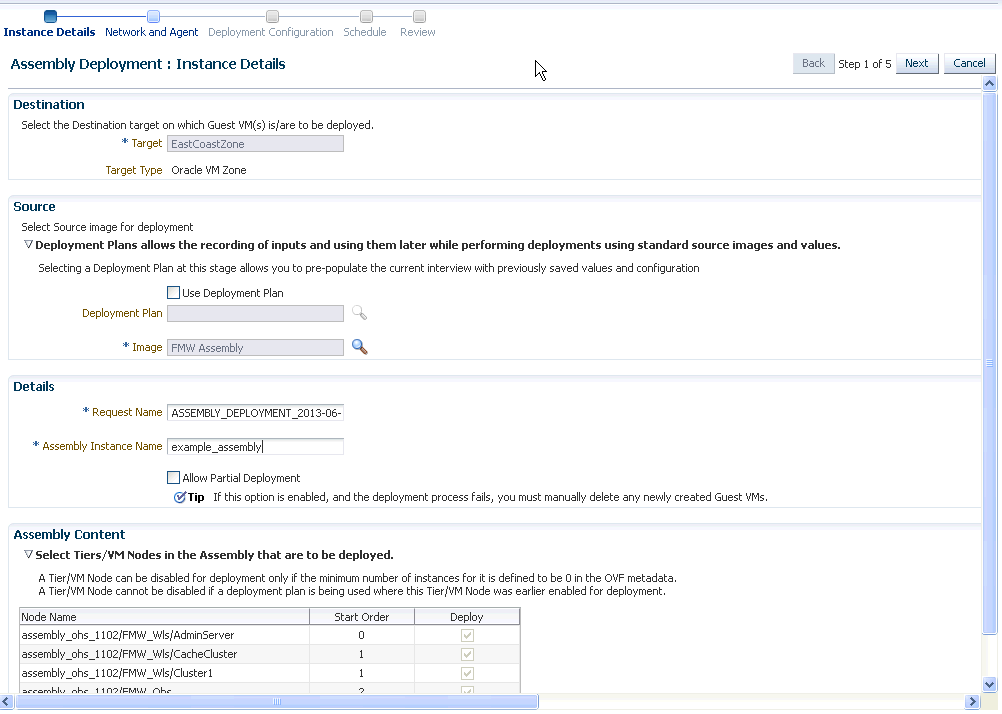
On the Assembly Deployment: Instance Details page, specify the following:
-
Target: Select the server pool on which the guest virtual machines are to be deployed.
-
Source: You can select either of the following options:
-
Deployment Plan: If you select the Use Deployment Plan check box, you can select a deployment plan (if available) with predefined configurations. The deployment plan will be used when the assembly is deployed. (image is selected automatically when the deployment plan is selected)
-
Image: The assembly component to be used for this deployment. This can either be a component present in the Software Library, or at an external location. If it is stored in an external location, specify the NFS or HTTP location where the component is stored. For example,
http://myvm_server/assemblyorfile://myvm_server/assembly.
-
-
Details:
-
Request Name: This is the name of the assembly deployment request.
-
Assembly Instance Name: The name to be assigned to the assembly instance.
-
Allow Partial Deployment: Select this option to enable partial deployment. By default, when a deployment plan fails, all virtual machines that have been created are automatically deleted. But if partial deployment is enabled, virtual machines are not deleted even if the deployment has failed.
-
-
Assembly Content: You can disable an assembly tier or a node from being deployed. By default, all nodes and tiers in the selected component are automatically deployed. To disable a node or tier from being deployed, unselect the Deploy checkbox in the table.
Note:
-
A tier or a node can be disabled for deployment if the minimum number of instances for the node or tier is set to 0 in the ovf metadata file.
-
If you choose to use a deployment plan where a tier or a node has been enabled for deployment, that node or tier cannot be disabled.
-
-
-
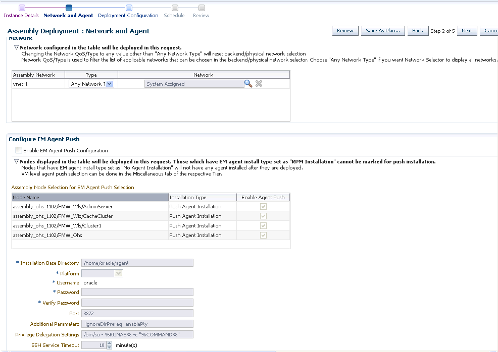
Click Next. In the Deploy Assembly: Network and Agent page, specify the physical public and private networks to be used for the assembly instance. A public network is used for external traffic. In a private network, the guest virtual machines can communicate only within a predefined network set up by the Cloud Administrator.
Assembly network refers to the logical network defined in the OVF metadata file and the network defined here is the actual physical network to which it is to be mapped. If you do not choose to associate the network explicitly, the mappings are automatically assigned.
-
Click on the Browse icon in the Network field. Specify if the network should be allocated by the system or selected manually.
-
If you want to install the Management Agent on an assembly tier (collection of Guest VMs) or selected guest virtual machines, check the Enable EM Agent Push Configuration check box. You can then select the tiers and / or the guest virtual machines on which the Management Agent is to be installed using the Agent Push approach in the Assembly Node Selection for the EM Agent Push Selection table.
-
Node Name: The name of the assembly tier on which the Management Agent is to be deployed.
-
Installation Type: The type of installation which can be Push Agent Installation, No Agent Installation, and RPM Installation.
-
Enable Agent Push: This checkbox is enabled only if the Enable EM Agent Push Configuration checkbox has been selected. Select this checkbox to select the tiers on which the Management Agent is to be installed by way of the Agent Push approach.
In a selected tier, you can also choose the guest virtual machines on which the Management Agent is to be installed.
Note:
-
If you select Push Agent Installation, you can specify the guest virtual machines that need to be enabled or disabled in the Miscellaneous tab.
-
For tiers that have the Management Agent as a product (as part of the binary package), the Enable Agent Push checkbox is disabled and only RPM Installation is available. In this case, you can specify the Management Agent details in the Product Configuration tab of the selected tier.
-
-
After you have specified the options to configure the Management Agent, enter the following details:
-
Installation Base Directory: This is the parent directory on the remote host where the Oracle home of the Management Agent is created.
-
Platform: The operating system on which the Management Agent is to be installed.
-
User: The name of the Oracle Install user is displayed here.
-
Port: The port used by the Management Agent for communication.
-
Password: This field is mandatory for PS5 assemblies if the Enable Agent Push Configuration checkbox has been selected.
-
Privilege Delegation Settings: Run as root.
-
SSH Service Timeout: The timeout settings for SSH.
-
Additional Parameters: Specify additional parameters to be used during the installation of the Management Agent. This field is pre-populated with the entry
-ignoreDirPrereq -enablePtyto ignore the prerequisite checks during installation.
-
-
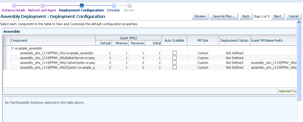
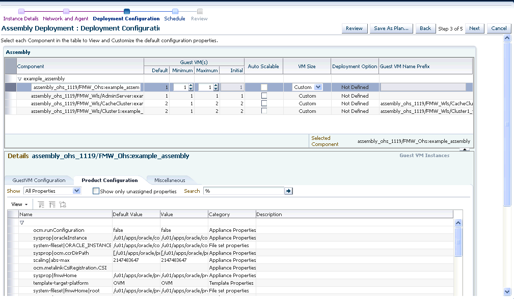
Click Next to go to the Deploy Assembly: Deployment Configuration page.
The following details are displayed:
-
Component: The assembly component that is being deployed.
-
Guest VMs: The default number of guest virtual machines as specified in the deployment profile appears. Specify the minimum and maximum number of guest virtual machines that are to be created.
-
Auto Scalable: Select this check box to indicate that the tier instances can be auto scaled based on their policies.
-
VM Size: The amount of memory to be allocated to the guest virtual machine. The virtual server should have sufficient memory to run the guest virtual machine. Otherwise, the guest virtual machine will be created, but will not be started. The size of the guest virtual machine (memory and CPU values).
-
Deployment Option: The deployment for this assembly instance.
-
Guest VM Name Prefix: This string will be used as a prefix in the guest virtual machine name. When a guest virtual machine is created using the Enterprise Manager, guest virtual machine names will be prefixed by the virtual machine name prefix you provide here and a number.
-
-
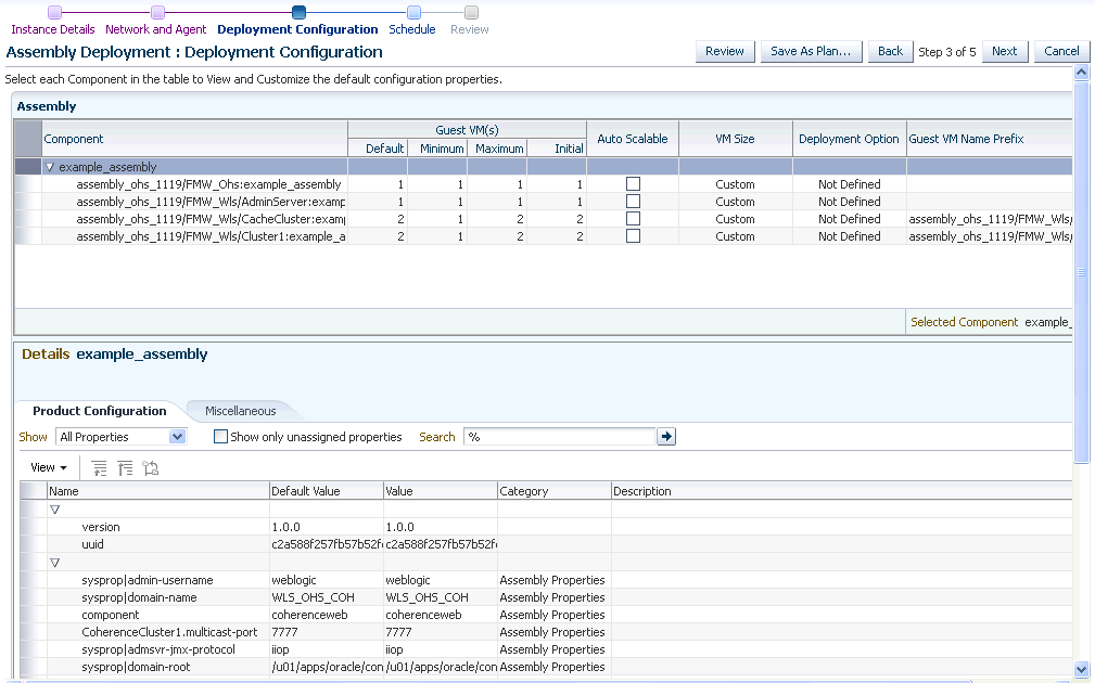
Select the assembly component to view and customize the default configuration properties.
-
Product Configuration: This tab shows the properties of the products in the assembly. You can choose to view All Properties or Required Properties. For each property, the default value and the current value is displayed. Select a property to modify the value if applicable.
-
Miscellaneous: You can create one or more anti-affinity groups. An anti-affinity group is a group of virtual machines cannot run on the same server. Click Add and enter the Group Name and select the guest virtual machines that are to be part of the anti-affinity group.
-
-
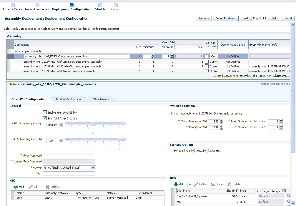
Click a row in the table to select the tier you want to configure. There are 3 tabs that can be configured for each tier in the assembly: Guest VM Configuration, Product Configuration, and Miscellaneous.
-
Let us look at the first tab: Guest VM Configuration. This tab allows you to modify the resource configuration parameters for all guest virtual machine instances of the selected assembly tier.
The following parameters can be configured:
-
Guest VM Configuration:
-
Enable High Availability: If you want to enable high availability for this guest virtual machine, select this check box. If this option is enabled, the virtual server is shut down or restarted, the guest virtual machine is migrated to or restarted on another virtual server.
Note:
High availability must be enabled both on the virtual server pool and on the guest virtual machine. If it is not enabled on both, high availability is disabled. -
CPU Scheduling Priority: Specify the priority of a guest virtual machine to access the physical CPUs, while competing with other guest virtual machines on the same virtual server. The higher the priority, the higher the stake of the guest virtual machine in claiming CPU cycles.
-
CPU Scheduling Cap (%): Restricts the amount of physical CPU that a guest virtual machine can use. Use this to constrain guest virtual machine resource allocation.
-
Root Password: Specify the operating system root password to log in to the guest virtual machine once it is up and running.
-
Keymap: The keyboard mapping that will be used by the guest virtual machine being cloned.
-
Tags: Specify one or more tags for the virtual machine. These tags are used to logical group the virtual machines and can be used to search for one or more virtual machines that meet a certain criteria.
-
Memory (in MB): The amount of memory to be allocated to the guest virtual machine. The virtual server should have sufficient memory to run the guest virtual machine. Otherwise, the guest virtual machine will be created, but will not be started.
-
CPUs: The number of CPU cores to assign to this guest virtual machine. This will show up as virtual CPU (VCPU) configuration parameter for the guest virtual machine.
-
Disk: Specify the storage type. You can use the Default type as specified by the server pool or select Override. If you select Override, you must specify the Storage QoS and click the Search icon in the Storage field to specify the Storage Type. In the Storage Type window, specify the following:
Clone Target Type: This can be Repository or Storage Array.
Clone Target: If you select Repository, select the storage location where the disk is to be created. If you select Storage Array, specify the type, which can be SAN or ISCSI storage server.
Clone Type: This can be Sparse or Non-Sparse Copy. A sparse copy is a disk image file of a physical disk, taking up only the amount of space actually in use; not the full specified disk size. A non-sparse copy is a disk image file of a physical disk, taking up the space equivalent to the full specified disk size, including empty blocks.
-
Disk: Every guest virtual machine is created with at least one disk. You can specify additional disks and their sizes. These disks will be added to the guest virtual machine. After the guest virtual machine is created, log in to the guest virtual machine and reformat and mount the additional disks. Click Add to add a storage device (disk).
Specify the name of the hard disk, its size, and QoS Priority Class. You can enable the disk I/O priority by setting an appropriate QoS Priority Class. The priority class ranges from 0 to 7. The priority class 0 has the highest priority, and 7 the lowest.Select the Shared Disk check box to share this disk between multiple guest virtual machines. You can enable the disk I/O priority by setting an appropriate QoS Priority Class. The priority class ranges from 0 to 7. The priority class 0 has the highest priority, and 7 the lowest.
-
NIC: Specify the network interfaces for this guest virtual machine. The minimum value is 1 and maximum is 8. Click Add to add a network interface and specify the following details:
Name: Enter a name for the network resource.
Network: Assembly Network / Backend network.
Network Type: Specify if the network type is Internet Routable, Non Internet Routable, or a predefined set of IP addresses.
IP Assignment: Select the protocol to be used to assign the IP address. This can be DHCP, Network Profile, or None.
The configuration parameters you specify here will be applied to all the guest virtual machine instances of the selected node. If you want to specify a different configuration for a guest virtual machine instance, click the Guest VM Instances option. In the Deployment Configuration: GuestVM Instance page, you can select a guest virtual machine instance from the View list and specify configuration parameters for that instance.
-
-
-
The next tab is Product Configuration. This tab shows the properties of the products in the tier. You can choose to view All Properties or Required Properties. For each property, the default value and the current value is displayed. Select a property to modify the value if applicable.
-
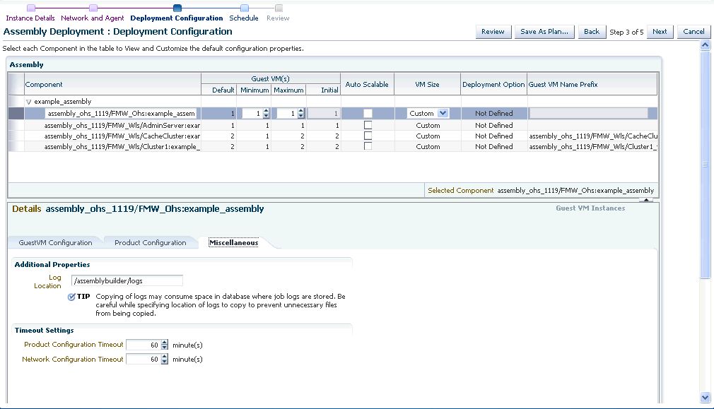
The next tab is the Miscellaneous tab.
-
-
Miscellaneous: Specify the following details:
-
Log File Location: Specify the directory in which the log files are to be stored.
-
Timeout Settings: Specify the timeout settings for the Product Configuration and Network Configuration. The default value is 60 minutes and this value can be modified for each Oracle VM Manager target. The timeout value specifies how long Enterprise Manager should wait for either Product Configuration or Network Configuration to be completed before proceeding with the assembly deployment.
-
-
-
If a tier has more than one Guest VM Instance, you can configure each Guest VM Instance separately. Select the tier for each Guest VM Instance has to be separately configured. Click the Guest VM Instances link on the top right corner of the lower region. The Deployment Configuration: Configure Guest VM Instance page appears. Click Edit VM Name to modify the name of the Guest VM Instance, specify a new name and click OK. You can modify the configuration of the Guest VM and click Continue to return to the Assembly Deployment: Deployment Configuration page.
-
Click Next. In the Assembly Deployment: Schedule page, specify the Start and End Date for the assembly deployment. The Start Date is the date on which the request is being submitted and the End Date is the date on which the assembly deployment instances are retired. Click Next.
-
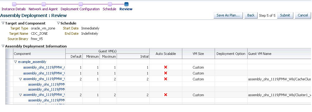
Click Next. The Assembly Deployment: Review page appears.
-
Click Next. Review the details entered so far. You can save as a plan that can be used later. Click Save as Plan, specify a name, and description for the plan. Select the folder in which the deployment plan is to be saved and click OK. Note that the deployment plan is stored as a software library component but can be created only through this procedure or by a Cloud API that generates a default deployment plan for an assembly.
-
Click Submit to submit the job. From the Enterprise menu, select Job, then select Activity to view the Job Activity page. This page shows the details of the submitted job. You can click on the Name link to view more details.
To view details of the deployment request, from the Enterprise menu, select Cloud, then select Oracle VM Infrastructure Request Dashboard. See Section 9.9, "Viewing the Infrastructure Request Dashboard" for details.
Note:
To ensure that Enterprise Manager has been configured correctly to push a 12c Management Agent automatically on the guest virtual machines when the assembly deployed, you must change the agentpush entry in the<OMS_ORACLE_HOME>/sysman/prov/agentpush/agentpush.propertiesfile as follows:From:
oracle.sysman.prov.agentpush.pdpShellOutEnabled=trueTo:
oracle.sysman.prov.agentpush.pdpShellOutEnabled=falseAfter this change has been made, you must restart the Oracle Management Service.
9.8.5 Provisioning a Guest Virtual Machine Using Oracle VM Templates
You can create one or more virtual machines by deploying a template. The deployment of the template is based on the constraints defined while the template was created. Typically, a template can contain an operating system, basic configuration (number of CPUs, memory, disk size), and preinstalled applications. The initial placement of virtual machines will be based on the storage, network and computational resources. Once a template is deployed, additional instances can be added (scale up) or removed (scale down) based on application demand.
Note:
Enterprise Manager supports deployment of legacy Oracle VM 2.2 style Templates. This templates are available in the.tgz file format. Guest virtual machines are created when these templates are deployed, but the you need to manually login to the VNC console of the newly created virtual machines to complete the network and product configuration. Also, unlike for Oracle Virtual Assemblies (.ova file format), Enterprise Manager does not automatically push the Management Agent for Oracle VM 2.2 Templates (.tgz file format).-
Enterprise Manager Cloud Control is set up to manage the cloud environment.
-
The template is available to the zone and you have sufficient privileges to deploy it.There are sufficient resources available in the zone for successful deployment.
Follow this process to deploy a template:
-
From the Enterprise menu, select Cloud, then select Oracle VM Infrastructure Home.
-
Right click on a virtual server pool target and select Deploy Template.
-
On the Select Target and Source page, select the following:
-
Select the target machine on which the guest virtual machine is to be created.
-
In the Source section, you can select either of the following options:
-
Deployment Plan: If you select the Use Deployment Plan check box, you can select a deployment plan (if available) with predefined configurations. Selecting a plan at this stage allows you to prepopulate the interview with previously saved values of deployment and configuration parameters.
-
Template: The template component to be used for this deployment. This can either be a component present in the Software Library, or at an external location. If it is stored in an external location, specify the NFS or HTTP location where the component is stored. For example,
http://myvm_server/templateorfile://myvm_server/template.
-
-
Click Next. The Template Deployment: Instance Details page appears.
This page contains the following sections:
-
Guest VM
-
Guest VM: Number of guest virtual machines to be deployed. Click Configure Each Guest VM Instance if you want to configure each guest virtual machine instance individually.
-
Guest VM Naming: You can choose either of the following options:
Generate Guest VM Names Using Prefix: This string will be used as a prefix in the guest virtual machine name. When a guest virtual machine is created using the Enterprise Manager, guest virtual machine names will be prefixed by the virtual machine name prefix you provide here and a number.
Upload Guest VM Names from File: If you select this option, you can Browse and upload a file with user defined guest virtual machine names. The guest virtual machine name cannot contain any special characters.
-
-
General Configuration
-
Enable High Availability: If you want to enable high availability for this guest virtual machine, select this check box. If this option is enabled, the virtual server is shut down or restarted, the guest virtual machine is migrated to or restarted on another virtual server.
Note:
High availability must be enabled both on the virtual server pool and on the guest virtual machine. If it is not enabled on both, high availability is disabled. -
Start VM After Creation: Specify whether the guest virtual machine should be started automatically after it is created.
-
CPU Scheduling Priority: Specify the priority of a guest virtual machine to access the physical CPUs, while competing with other guest virtual machines on the same virtual server. Higher the priority, higher is the stake of the guest virtual machine in claiming CPU cycles.
-
CPU Scheduling Cap (%): Restricts the amount of physical CPU that a guest virtual machine can use. Use this to constrain guest virtual machine resource allocation.
-
Keymap: The keyboard mapping that will be used by the guest virtual machine being cloned.
-
Tags: Specify one or more tags for the virtual machine. These tags are used to logical group the virtual machines and can be used to search for one or more virtual machines that meet a certain criteria.
-
Memory (in MB): The amount of memory to be allocated to the guest virtual machine. The virtual server should have sufficient memory to run the guest virtual machine. Otherwise, the guest virtual machine will be created, but will not be started.
-
CPU Cores: The number of CPU cores to assign to this guest virtual machine. This will show up as virtual CPU (VCPU) configuration parameter for the guest virtual machine.
-
-
VM Size: The amount of memory to be allocated to the guest virtual machine. The virtual server should have sufficient memory to run the guest virtual machine. Otherwise, the guest virtual machine will be created, but will not be started. The size of the guest virtual machine (memory and CPU values). Select the VM Size which can be Custom or Medium. If you select Custom, specify the Memory size and the number of CPUs.
-
NIC: Specify the network interfaces for this guest virtual machine. The minimum value is 1 and maximum is 8. Click Add to add a network interface and specify the following details:
-
Name: Enter a name for the network resource.
-
Network Type: Specify if the network type is Internet Routable, Non Internet Routable, or a predefined set of IP addresses.
-
IP Assignment: Select the protocol to be used to assign the IP address.
-
-
Disk:
The list of available disks appears in the Disk section. Click Add to add an additional storage. In the Add Storage Device window, enter the name of the disk and its size. Indicate if it is a shared disk and specify the priority of a guest virtual machine to access the physical CPUs, while competing with other guest virtual machines on the same virtual server. Higher the priority, higher is the stake of the guest virtual machine in claiming CPU cycles.
-
-
Click Next and Review the details entered so far.
-
Review the details entered so far. You can save as a plan that can be used later. Click Save as Plan, specify a name, and description for the plan. Select the folder in which the deployment plan is to be saved and click OK. If you do not wish to save the deployment procedure, click Submit to submit the job. From the Enterprise menu, select Job, then select Activity to view the Job Activity page. This page shows the details of the submitted job. You can click on the Name link to view more details.
To view details of the deployment request, from the Enterprise menu, select Cloud, then select Oracle VM Infrastructure Request Dashboard. See Section 9.9, "Viewing the Infrastructure Request Dashboard" for details.
9.8.6 Provisioning a Guest Virtual Machine Using an ISO Image
ISO images are imported into Enterprise Manager from installation media. You can create one or more virtual machines by deploying an ISO image.
-
Enterprise Manager Cloud Control is set up to manage the cloud environment.
-
The ISO image is available to the zone and you have sufficient privileges to deploy the image.There are sufficient resources available in the zone for successful deployment.
-
The Domain Type of the guest virtual machine being deployed must be set to HVM (hardware virtualized).
Follow this process to deploy an ISO image:
-
From the Enterprise menu, select Cloud, then select Oracle VM Infrastructure Home.
-
Right click on a virtual server pool target and select Deploy ISO.
-
On the Select Target and Source page, the server pool target on which the ISO image is to be deployed appears. In the Destination section, you can select either of the following:
-
Deployment Plan: If you select the Use Deployment Plan check box, you can select a deployment plan (if available) with predefined configurations. Selecting a plan at this stage allows you to pre-populate the interview with previously saved values of deployment and configuration parameters.
-
ISO: The ISO image to be used for this deployment. This can either be a component present in the Software Library, or at an external location. If it is stored in an external location, specify the NFS or HTTP location where the component is stored. For example,
http://myvm_server/imageorfile://myvm_server/image.
-
-
Enter the name of the request and click Next to continue. The ISO Deployment: Deployment Configuration page appears.
-
This page contains the following sections:
-
Guest VM
-
Guest VM: Number of guest virtual machines to be deployed. Click Configure Each Guest VM Instance if you want to configure each guest virtual machine instance individually.
-
Guest VM Naming: You can choose either of the following options:
Generate Guest VM Names Using Prefix: This string will be used as a prefix in the guest virtual machine name. When a guest virtual machine is created using the Enterprise Manager, guest virtual machine names will be prefixed by the virtual machine name prefix you provide here and a number.
Upload Guest VM Names from File: If you select this option, you can Browse and upload a file with user defined guest virtual machine names. The guest virtual machine name cannot contain any special characters.
-
-
General Configuration
-
Enable High Availability: If you want to enable high availability for this guest virtual machine, select this check box. If this option is enabled, the virtual server is shut down or restarted, the guest virtual machine is migrated to or restarted on another virtual server.
Note:
High availability must be enabled both on the virtual server pool and on the guest virtual machine. If it is not enabled on both, high availability is disabled. -
Start VM After Creation: Specify whether the guest virtual machine should be started automatically after it is created.
-
CPU Scheduling Priority: Specify the priority of a guest virtual machine to access the physical CPUs, while competing with other guest virtual machines on the same virtual server. Higher the priority, higher is the stake of the guest virtual machine in claiming CPU cycles.
-
CPU Scheduling Cap (%): Restricts the amount of physical CPU that a guest virtual machine can use. Use this to constrain guest virtual machine resource allocation.
-
-
VM Size: The amount of memory to be allocated to the guest virtual machine. The virtual server should have sufficient memory to run the guest virtual machine. Otherwise, the guest virtual machine will be created, but will not be started. The size of the guest virtual machine (memory and CPU values). Select the VM Size which can be Custom or Medium. If you select Custom, specify the Memory size and the number of CPUs.
-
NIC: Specify the network interfaces for this guest virtual machine. The minimum value is 1 and maximum is 8. Click Add to add a network interface and specify the following details:
-
Name: Enter a name for the network resource.
-
Network Type: Specify if the network type is Internet Routable, Non Internet Routable, or a predefined set of IP addresses.
-
IP Assignment: Select the protocol to be used to assign the IP address.
-
-
Disk:
The list of available disks appears in the Disk section. Click Add to add an additional storage. In the Add Storage Device window, enter the name of the disk and its size. Indicate if it is a shared disk and specify the priority of a guest virtual machine to access the physical CPUs, while competing with other guest virtual machines on the same virtual server. Higher the priority, higher is the stake of the guest virtual machine in claiming CPU cycles.
-
-
Click Next. In the Schedule page, specify when the ISO image is to be deployed and click Next.
-
Review the details entered so far. You can save as a plan that can be used later. Click Save as Plan, specify a name, and description for the plan. Select the folder in which the deployment plan is to be saved and click OK. If you do not wish to save the deployment procedure, click Submit to submit the plan and complete the process.
9.8.7 Creating PXE Bootable Guest Virtual Machines
One of the key requirements of provisioning is the hardware server's ability to boot over the network instead of a diskette or CD-ROM. There are several ways computers can boot over a network, and Preboot Execution Environment (PXE) is one of them. PXE is an open industry standard supported by a number of hardware and software vendors. A detailed document on PXE specification can be found at http://www.pix.net/software/pxeboot/archive/pxespec.pdf.
You can create a network bootable (PXE boot) virtual machine that has the minimum configuration information, then start the virtual machine through Preboot Execution Environment (PXE) over a network later to install the guest operating system.
-
Enterprise Manager Cloud Control is set up to manage the cloud environment.
-
There are sufficient resources available in the zone for successful deployment.
Follow this process to deploy an ISO image:
-
From the Enterprise menu, select Cloud, then select Oracle VM Infrastructure Home.
-
Select a Virtual Server Pool target. Select Deploy PXE from the Virtual Server Pool menu.
-
On the Select Target and Source page, select the following:
-
Select the target machine on which the guest virtual machines are to be deployed.
-
Select the deployment plan to be used while creating PXE bootable guest virtual machines. The Deployment Plan contains pre-configured values and configuration parameters. This is an optional field.
-
-
Click Next. In the General Configuration page, enter the following details:
-
Name of the guest virtual machine to be deployed. If you are deploying more than one guest virtual machine, you can use a prefix or upload a file with user defined guest virtual machine names.
-
Number of guest virtual machines to be deployed. Click Configure Each Guest VM Instance if you want to configure each guest virtual machine instance individually.
-
Select the VM Size which can be Custom or Medium. If you select Custom, specify the Memory size and the number of CPUs.
-
Specify the priority of a guest virtual machine to access the physical CPUs, while competing with other guest virtual machines on the same virtual server. Higher the priority, higher is the stake of the guest virtual machine in claiming CPU cycles.
-
Specify the cap to restrict the amount of physical CPU that a guest virtual machine can use.
-
CPU Cores: The number of CPU cores to assign to this guest virtual machine. This will show up as virtual CPU (VCPU) configuration parameter for the guest virtual machine.
-
Keymap: The keyboard mapping to be used for the guest virtual machine.
-
Memory (in MB): The amount of memory to be allocated to the guest virtual machine. The virtual server should have sufficient memory to run the guest virtual machine. Otherwise, the guest virtual machine will be created, but will not be started.
-
CPU Cores: The number of CPU cores to assign to this guest virtual machine. This will show up as virtual CPU (VCPU) configuration parameter for the guest virtual machine.
-
In the NIC Configuration section, you can specify the number of virtual network interfaces for this guest virtual machine. The minimum value is 1 and the maximum value is 8. You can add one or more network interfaces or edit existing ones.
-
Enterprise Manager Cloud Control provides a VNC console to the newly created guest virtual machine. This is the VNC password to access the VNC console.
-
Select a Domain Type for the virtual machine:
-
xen_hvm (hardware virtualization, or fully virtualized): Enables you to select an ISO file from which to create the virtual machine.
-
xen_pvm (para-virtualized): Enables you to select a location for the mounted ISO file from which to create the virtual machine. Before you create the virtual machine using the paravirtualized method, mount the ISO file on an NFS share, or HTTP or FTP server. The ISO file must be available in the relevant repository.
-
xen_hvm_pv_drivers: Identical to xen_hvm but with additional paravirtualized drivers for improved performance of the virtual machine. This Domain Type is used to run Windows guest operating systems with an acceptable performance level.
-
-
Select the Enable High Availability option if you want the guest virtual machine to run automatically on a different virtual server if the earlier virtual server shuts down.
-
Select the Start VM After Creation check box to indicate whether the machine should automatically be started after it is created.
-
The list of available disks appears in the Disk section. Click Add to add an additional storage.
-
-
Click Next. In the Schedule page, specify when the PXE bootable guest virtual machines are to be created and click Next.
-
Review the details entered so far and click Submit to create the PXE bootable guest virtual machines.
9.9 Viewing the Infrastructure Request Dashboard
The SSA Administrator can use the Request Dashboard to track the status of requests and reservations. The SSA administrator can view the requests across all zones for all users. The requests the SSA user can view depends on his zone and his instance level privileges.
Prerequisites
-
Enterprise Manager Cloud Control is set up to manage the cloud environment.
-
Appropriate self service users have been defined in the LDAP directory.
-
Requests and reservations for resources have been submitted.
To view the Infrastructure Request Dashboard, follow these steps:
-
From the Enterprise menu, select Cloud, then select Oracle VM Infrastructure Request Dashboard. The Infrastructure Cloud Requests Dashboard appears.
-
The following charts are displayed:
-
Latest 10 Failed and Pending Requests
-
Oldest 10 Running Requests
-
Request Summary - Failed, Successful, and Partially Successful Requests
-
Average Request Wait Time (Zone)
-
Average Request Wait Time (Assemblies and Templates)
-
Average Request Processing Time (Zone)
-
Average Request Processing Time (Assemblies and Templates)
-
-
Click on the View All Requests link to go to the All Cloud Requests page.
-
In this page, you can search for one of the following:
-
Request Name: The name of the request.
-
Request Type: The type of request that you want to view. This can be Assembly Deployment, Template Deployment, ISO Deployment, PXE Deployment, Clone Guest VM, Update Guest VM.
-
Requesting Application: The application making the request. You can view only Self Service requests from this dashboard.
-
Status: The status of the request such as Successful, Canceled, Scheduled, Error Ending, and so on.
-
-
For each request type you select, you can view the Request Name, Request Type, Created By, Status, Begin Date, End Date, Memory, CPU, VMs, and so on. You can also select a request and click Delete to remove the request.
-
Click on a Request Name link to drill down to the Request Details page.
9.9.1 Viewing Request Details
The Request Details page shows the details of the selected request. The name of the request, type, the OVM Manager associated with the request, status, date on which it was created, and so on are displayed.
-
General: This section displays the name of the request, request type, target name, and other details.
-
Deployment: This section shows the name of the requests and the targets that have been deployed. Click on request link to drill down to the Job Details page. Click on a target link to drill down to the Home page of the target.
9.9.2 Viewing the Assembly / Tier Instance Page
To view the Home page for the assembly or tier instance, follow these steps:
-
From the Enterprise menu, select Cloud, then select Oracle VM Infrastructure Request Dashboard.
-
The Infrastructure Request Dashboard page appears. Click the All Requests link in the Requests table.
-
In the All Requests page, click on an assembly deployment request name in the table. The Assembly Deployment page appears. Click on the Deployment tab. The assembly instance that has been deployed is displayed.
-
Click on the Assembly Instance link. The following page appears.
-
General: This section shows the name of the assembly, the target on which it was deployed, the total number of Guest VMs, the date on which it was created, and the owner of this assembly instance.
-
Status: The status of the most affected members over the last 24 hours is displayed. Click on a Name link to drill down to the target Home page.
-
Issues Overview: Shows the various incidents and policy violations that have occurred in the last 24 hours.
-
Affinity Relations: The rules that have been defined for the assembly or tier are displayed here. For example, you can define rules to specify whether two guest VMs can exist together on the same server or server pool, rules to ensure that two guest VMs must exist on the same server, and so on.
-
Members: The members in this instance, their status, and the installed software is displayed.
-
Requests: The name of the request specified during deployment. Click on the link to navigate to the Deployment page.
