Setting up Load Balancers
Setting up load balancers allows Business Transaction Management to model the flow of traffic correctly and allows you to access the load balancer's administrative console from the Business Transaction Management console.
This section also explains how you set up an F5 device to load balance messages from one observer to multiple monitors. It includes the following sections:
Setting up a Load Balancer
If you deploy a service in more than one container, Business Transaction Management understands these replicated endpoints are part of the same service, and it can infer the existence of a load balancer that routes messages to these replicated endpoints. That is, Business Transaction Management can model the flow of traffic correctly in dependency diagrams even though it does not monitor the flow of traffic through the load balancer itself. However, without your help, Business Transaction Management cannot provide more detailed information about the inferred load balancer. Setting up a load balancer means giving Business Transaction Management information that allows it to do the following:
-
provide information about the load balancer in the management console; for example, the name you want displayed for it and the vendor associated with it
-
identify the device hosting the load balancer
-
give you easy access to the load balancer's administrative console
-
specify the lifecycle phase of the load balancer device and all the endpoints that are created within it
Setting up a load balancer starts with registering it, which you can do using either the CLI command registerDevice or using the management console. In some cases, you might also need to specify an entry point to the load balancer and define target entry points that correspond to the destinations where messages are being routed.
This section explains some basic terms related to load balancing, describes the devices that Business Transaction Management supports, and explains the following user tasks:
-
Registering a load balancer
-
Modifying information about a load balancer
-
Adding entry points to show routing relationships
-
Unregistering a load balancer
Business Transaction Management supports a variety of load-balancing devices. It provides the greatest support for F5 load balancers, but it can also recognize and model other hardware and software load balancers.
Basic Terms
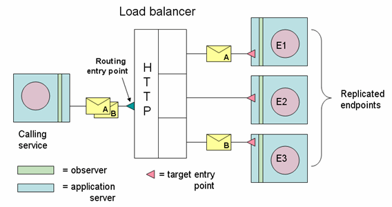
The figure below illustrates the use of a load balancer to route messages A and B to three replicated endpoints (E1, E2, E3). Note the elements marked: routing entry point and target entry point. The load balancer receives messages at the routing entry point and forwards them to the target entry points. There are situations in which you might have to supply entry point information after registering the load balancer, as described in the next section.
Supported Devices
Business Transaction Management can work with three kinds of load balancers: F5 devices, other hardware devices, and software load balancers. The work you need to do to help Business Transaction Management model message traffic varies with each case:
-
Business Transaction Management knows the most about the F5 device and requires only a single registration step to derive the information it needs. Business Transaction Management might perform additional discovery passes to complete its picture of an F5's role in message routing.
-
For hardware load-balancers, Business Transaction Management can usually detect and model any routing entry points automatically, based on the information in the HTTP Host headers of the observed messages. However, explicitly registering the device (using the CLI command
registerDeviceor using the management console) allows Business Transaction Management to display information about the device's location and other attributes.If you do not register any device, Business Transaction Management automatically registers a default load balancer and is able to model the flow of messages through this device. In this case, you can still edit the Profile page for the default load balancer to specify a name, the base address, admin UI, and vendor.
If the observed messages do not carry information about their original recipient (the load balancer) in the HTTP Host headers, you will need to register the device and specify routing and target entry points in the same way as you do for software balancers, described next.
-
For load balancers implemented by software that make a separate HTTP connection to the back-end servers (rather than just forwarding HTTP messages), you need to describe the routing relationships in order for Business Transaction Management to model them correctly. To do this you must register the device, add an entry point for the load balancer, and specify target entry points that correspond to the destinations where messages are being routed.
Default Load Balancer
The default load balancer is either the first load balancer registered or the one you set to be the default using the setDefaultLoadBalancer command.
The calling service uses a routing entry point to communicate with the load balancer. Business Transaction Management discovers the routing entry point by observing messages. If no load balancer has yet been registered, Business Transaction Management creates a default load balancer and assigns the discovered routing entry port to it. Any newly discovered routing entry points will be modeled as part of the default device unless they belong to a registered F5 load balancer.
You can edit the profile of the default load balancer that was created for you, to provide additional details or, if you prefer, you can unregister it and register your actual load balancer explicitly.
Registering a Load Balancer Using the Management Console
You can register a hardware or software load balancer using the CLI command registerDevice or using the console.
After you complete the registration, the device is listed in the summary pane when you select Explorer > Devices in the navigator.
To register a hardware or software load balancer using the console:
-
Select Admin > Register > Device and then choose F5 Networks to register an F5 load balancer, or choose Other to register any other load balancer.
-
In the ensuing dialog, specify values as shown in the following table.
Field Description Vendor Not editable for F5; required for other load balancers. If you chose F5 Networks in Step 1, this field is set to the non-editable value of F5.
If you chose Other, specify the name of the vendor of your load balancer. This field is purely descriptive. You can specify any value (except F5). The specified value is displayed in the Management Console.
Device Name Required. Specify the friendly name for your load balancer. This name is displayed in the Management Console.
Notes Optional. Add any notes to remind you of the nature or purpose of this load balancer. Lifecycle phase Select the lifecycle phase from the drop-down list. Available values are deprecated,development,production,staging, andtest. These are case insensitive.Configuration URL Required and displayed only if you chose F5. Specify the URL of the F5 console in the following format:
https://managementPortIP/iControl/iControlPortal.cgi
Replace managementPortIP with the appropriate host name and port number. This URL normally ends with iControl/IControlPortal.cgi.
Username and Password This value is required and displayed only if you chose F5 Networks. Specify the user name and password of an account on your F5 load balancer. A user role of Guest provides sufficient privileges.
You can encrypt passwords using the
encryptPasswordCLI command, for example:btmcli encryptPassword -password "myPassword"Base Address Required and displayed only if you chose Other. Specify the base address of the URL for your load balancer, for example:
https://myLoadBalancer:443/
Administrator URL Optional and displayed only if you chose Other. Specify the URL of your load balancer's HTML administrative console. A link to this URL is displayed in the Business Transaction Management Management Console to provide easy access to your load balancer's console.
This flag is not needed for F5 load balancers because Business Transaction Management obtains the URL automatically.
-
Click Apply.
-
If needed, assign routing entry points and target entry points as described in the Adding Entry Points to Show Routing Relationships.
Modifying Information About a Load Balancer
You can modify information about a device you have already registered or about a default device.
To modify information about a device:
-
Select Explorer > Devices from the navigator.
-
In the summary area, select the device whose attributes you want to specify or edit.
-
Select Modify > Edit Profile for deviceName.
-
Modify the fields of interest (as described when registering the device) in the ensuing dialog.
-
Click Apply.
Adding Entry Points to Show Routing Relationships
In most cases, Business Transaction Management automatically detects and models routing relationships by observing message traffic and reading destination information from the message headers. However, if the observed messages do not carry information about their original recipient (the load balancer) in the HTTP Host header, you will need to manually create a routing entry point to the load balancer. You will also need to add target entry points to indicate where the messages are being routed.
If you do not specify routing relationships, Business Transaction Management will not be able to draw contiguous dependency flows. In the case of transactions, you could still connect these disjoint flows by linking related services using manual keys.
To add routing entry points and target entry points:
-
Select Explorer > Devices from the navigator.
-
In the summary area, select the device whose routing relationships you want to clarify.
-
Select Create > Entry Point for deviceName.
-
In the ensuing Create Entry Point tool, specify the following information: --In the Hosted on section, specify the IP address and port number where the load balancer is receiving observation messages (the HTTP port). -- Click the Add Target Entry Point and choose a destination from the drop down list. Each destination refers to a target entry point where the load balancer is routing messages. Do this for each potential destination.Note: There will be more entry points on the drop-down list than the router is using. Some of these might be addresses to which another load balancer is sending messages. (Basically, the drop down list shows every entry point known to the sphere.)
-
Click Apply.
Unregistering a Load Balancer
You can only use the management console to unregister a load balancer.
To unregister a load balancer:
-
Select Explorer > Devices from the navigator.
-
In the summary area, select the name of the device you want to unregister.
-
Select Modify > Delete deviceName Registration
-
Confirm deletion action by clicking Delete in the next dialog.
Registering an F5 Network Device
Registering an F5 network device allows Business Transaction Management to read F5 configuration information and to model that device (its entry points and the routing policies applied to them) in the management console. You can only register devices that are running iControl v9.x software.
Before you register the device, select Administration > System Services from the navigator, and check the services listed to make sure that the F5 Intermediary Adapter service is up and enabled.
To register an F5 Network Device
-
Select Admin > Register > Device > F5 Networks.
-
Specify a name for the device. This name will be used to identify the F5 device in the Explorer > Devices view that you can access from the navigator.
-
Add any notes to identify the device or what use you intend to make of it. These notes will appear in the Profile tab for the device after it has been registered with the Sphere.
-
Select the life cycle phase of your deployment from the drop list. Values include Deprecated, Development, Production, Staging, Test, and Unknown. These values are not checked or enforced in any way; they are available only to help you organize your work.
-
Specify the URL for the F5 console as illustrated in the following example
https://ManagementIP/iControl/iControlPortal.cgifor ManagementIP specify the IP address of the management port your BIG-IP Load Balancer is configured to listen on.
-
Enter the user name and password for the administrator's account of the F5 device.
-
CLick Apply.
-
To view device information, select Explorer > Devices in the navigator.
You can also use the CLI command registerDevice to register an F5 network device.
Configuring an F5 Device to Work with Replicated Monitors
Monitoring in Business Transaction Management relies on the communication that takes place between an observer that monitors message traffic through a given service and a monitor that analyzes and stores the data obtained by the observer.
To scale your system and make it fault tolerant, you can associate several replicated monitors (monitor group) with observers. Replicated monitors require a third-party load balancer that can route messages from observers to the monitors. This section explains how you set up an F5 device to load balance messages from an observer to two or more monitors.
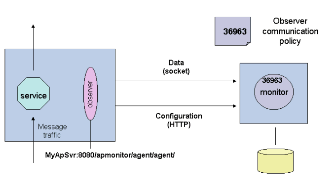
In order to understand F5 setup, it is helpful to review the mechanism that allows an observer to communicate with a single monitor; this is illustrated in the following figure:

Description of the illustration single_monitor.gif
As shown in the figure, communication between the observer and the monitor proceeds by means of two paths:
-
The observer queries the monitor for configuration information and receives that information from the monitor's HTTP port. (Although configuration data is mostly flowing from the monitor to the observers, the connection is made by the observer.) This port is specified using the AP_NANO_CONFIG_URL Java system property or using the
AmberPoint:NanoConfigRLWindows key, depending on the platform. The sample URL shown in the figure isMyApSvr:8080/apmonitor/agent/agent. When the observer starts up, it sends a request to this URL to get configuration information, which tells it what it should measure and how often. In this way, the observer can be reconfigured dynamically as your need for different kinds of information changes. -
The observer sends measurement data to the monitor at the socket port specified in the Observer communication policy. By default, this port is 36963.
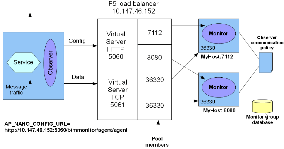
When you set up communication between your observers and replicated monitors by way of an F5 device, the device must be configured to include these same two (configuration and data) paths for every replicated monitor you add. The next figure shows how the F5 device connects an observer with the replicated monitors.

Description of the illustration replicated_monitors.gif
Creating a scheme like the one above involves configuring the F5 device, setting the Java system property or Windows key, and defining the observer communication policy for the replicated monitors.
When you set up the F5 device, you must use the admin console for that device to do the following:
-
Create an HTTP virtual server to be used by the observer to get configuration information. This is shown at port 5060 above.
Assign a pool to the HTTP virtual server with member port numbers that correspond to the HTTP ports of the monitors to which you are connecting. As illustrated, the pool for the HTTP virtual server includes ports 11080 and 11081.
-
Create a socket virtual server to be used by the observer to send data to the socket ports of the monitors. This is at port 5061 above. Assign a pool to the socket server with member port numbers that correspond to the socket (data) ports of the monitors to which you are connecting. As illustrated, the pool for the socket virtual server includes the ports at 36330 on each host machine.
When you set the AP_NANO_CONFIG_URL Java system property or the AmberPoint:NanoConfigURL Windows key, you must provide a value like the following:
http://10.147.46.152:5060/btmmonitor/agent/agent/
Note the bold portion of the URL: it is the IP address of the F5 device (host) and the virtual sever HTTP port. (Of course, these numbers will be different for your deployment.)
The values you specify for the observer communication policy correspond to the values defined for the F5 device as follows:
| Observer communication policy (Through router to monitor group) | F5 device values |
|---|---|
| Router IP address | The IP address of the F5 device. With reference to the figure, this would be 10.147.46.152. |
| Router port number | The virtual server socket number. With reference to the figure, this would be 5061. |
| Monitor port number | One of the pool member ports. With reference to the figure, this would be 36630.
If, for some reason, the replicated monitors are located on the same machine, the port numbers for each monitor would be different, and you would need a different observer communication policy for each monitor. |
It does not matter whether you define the observer communication policy first and the F5 second. What matters is that the socket ports assigned to the monitors correspond to those defined for the virtual server socket pool in the F5 device.
This section assumes that a certain amount of work has already been done to deploy and register the replicated monitors and to create the monitor group. Consult the Business Transaction Management Installation Guide for information on how to do this, and on how to define the observer communication policy.
