| Skip Navigation Links | |
| Exit Print View | |

|
Managing Oracle Solaris 11.1 Network Performance Oracle Solaris 11.1 Information Library |
| Skip Navigation Links | |
| Exit Print View | |

|
Managing Oracle Solaris 11.1 Network Performance Oracle Solaris 11.1 Information Library |
1. Introduction to Network Performance Management
4. Administering Bridged Networks (Tasks)
7. Exchanging Network Connectivity Information With LLDP
8. Working With Data Center Bridging Features in Oracle Solaris
9. Edge Virtual Bridging in Oracle Solaris
10. Integrated Load Balancer (Overview)
11. Configuring Integrated Load Balancer
12. Managing Integrated Load Balancer
13. Virtual Router Redundancy Protocol (Overview)
A. Link Aggregation Types: Feature Comparison
ILB supports stateless Direct Server Return (DSR) and Network Address Translator (NAT) modes of operation for IPv4 and IPv6, in single-legged and dual-legged topologies.
Stateless DSR topology
NAT mode (full-NAT and half-NAT) topology
In DSR mode, ILB balances the incoming requests to the back-end servers, but lets the return traffic from the servers to the clients bypass it. However, you can also set up ILB to be used as a router for a back-end server. In this case, the response from the back-end server to the client is routed through the system that is running ILB. ILB's current implementation of DSR does not provide TCP connection tracking (meaning that it is stateless). With stateless DSR, ILB does not save any state information of the processed packets, except for basic statistics. Because ILB does not save any state in this mode, the performance is comparable to the normal IP forwarding performance. This mode is best suited for connectionless protocols.
Advantages:
Better performance than NAT because only the destination MAC address of packets is changed and servers respond directly to clients.
There is full transparency between the server and the client. The servers see a connection directly from the client IP address and reply to the client through the default gateway.
Disadvantages:
The back-end server must respond to both its own IP address (for health checks) and the virtual IP address (for load-balanced traffic).
Because the load balancer maintains no connection state (meaning that it is stateless), adding or removing servers will cause connection disruption.
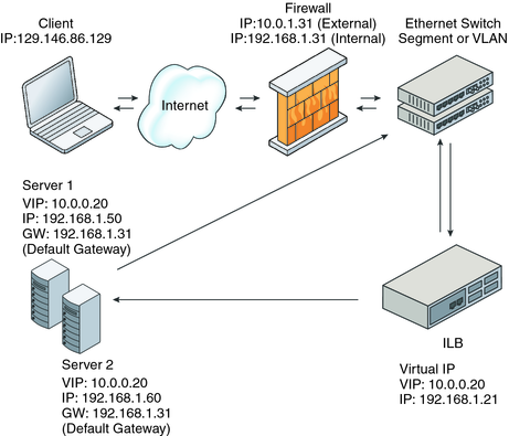
The following figure shows the implementation of ILB using the DSR topology.
Figure 10-1 Direct Server Return Topology

In this figure, both back-end servers are in the same subnet (192.168.1.0/24) as the ILB box. The servers are also connected to the router so that they can reply directly back to clients after getting a request forwarded by the ILB box.
ILB uses NAT in stand-alone mode strictly for load-balancing functionality. In this mode, ILB rewrites the header information and handles the incoming as well as the outgoing traffic. ILB operates in both the half-NAT and full-NAT modes. However, full-NAT also rewrites the source IP address, making it appear to the server that all connections are originating from the load balancer. NAT does provide TCP connection tracking (meaning that it is stateful). NAT mode provides additional security and is best suited for Hypertext Transfer Protocol (HTTP) (or Secure Sockets Layer (SSL)) traffic.
Advantages:
Works with all back-end servers by changing the default gateway to point to the load balancer.
Because the load balancer maintains the connection state, adding or removing servers without connection disruption is possible.
Disadvantages:
Slower performance than DSR because processing involves manipulation of the IP header and servers send responses to the load balancer.
All the back-end servers must use the load balancer as a default gateway.
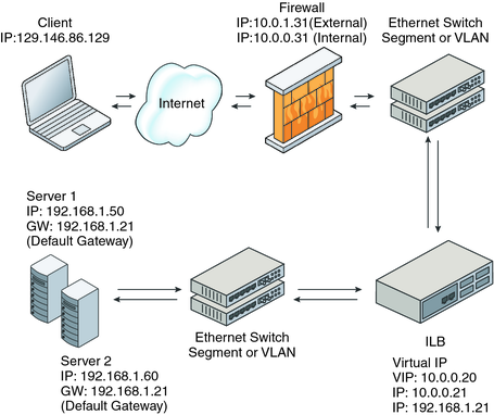
The general implementation of the NAT topology as shown in the following figure.
Figure 10-2 Network Address Translation Topology

In this case, all requests to the VIP go through the ILB box and are forwarded to the back-end servers. All the replies from the back-end servers pass through the ILB box for NAT.
 | Caution - The NAT code path that is implemented in ILB differs from the code path that is implemented in the IP Filter feature of Oracle Solaris. Do not use both of these code paths simultaneously. |
In the half-NAT mode of ILB operation, ILB rewrites only the destination IP address in the header of the packets. If you are using the half-NAT implementation, you cannot connect to a virtual IP (VIP) address of the service from the same subnet on which the server resides. The following table shows the IP addresses of the packets flowing between client and ILB, and between ILB and back-end servers.
Table 10-1 Request Flow and Response Flow for the Half-NAT Implementation When the Server and Client are on Different Networks
|
If you connect the client system to the same network as that of the servers, the intended server responds directly to the client. The fourth step does not occur. Hence, the source IP address for the server response to the client is invalid. When the client sends a connection request to the load balancer, the response occurs from the intended server. Henceforth, the client's IP stack correctly drops all the responses.
In that case, the request flow and response flow proceed as shown in the following table.
Table 10-2 Request Flow and Response Flow for the Half-NAT Implementation When the Server and Client are on the Same Network
|
In the full-NAT implementation, the source and destination IP addresses are rewritten to ensure that the traffic goes through the load balancer in both directions. The full-NAT topology makes it possible to connect to the VIP from the same subnet that the servers are on.
The following table depicts the IP addresses of the packets flowing between a client and ILB, and between ILB and a back-end server using the full-NAT topology. No special default route using the ILB box is required in the servers. But note that the full-NAT topology requires the administrator to set aside one or a range of IP addresses to be used by ILB as source addresses to communicate with the back-end servers. Assume that the addresses used belong to subnet C. In this scenario, the ILB behaves as a proxy.
Table 10-3 Request Flow and Response Flow for the Full-NAT Implementation
|