5 Creating and Configuring the Cartridges
This chapter contains information on the requirements for creating and configuring the Oracle Communications Offline Mediation Controller IMS CDF/CGF cartridges.
Creating and Configuring the Diameter CC
The Diameter CC collects raw diameter data from IMS devices and passes that data to the next node in the chain, the Diameter Parser EP.
To create and configure the Diameter CC:
-
Log on to Offline Mediation Controller Administration Client.
The Node Hosts & Nodes (logical view) screen appears.
-
In the Mediation Hosts table, select a host.
-
In the Nodes on Mediation Host section, click New.
The Create a Node dialog box appears.
-
Select the Wireless service solution and click Next.
-
Select Collection Cartridge (CC) and click Next.
-
Select Diameter and click Finish.
-
In the node configuration window, enter a name for the node and accept the default rule file.
-
On the General tab, accept the default field values or make changes where necessary. The General tab contains generic settings that are applicable to all collection cartridges in Offline Mediation Controller. The field definitions are as follows:
-
Debug Level - Each cartridge produces a separate log file in addition to the administration server and node manager log files. This setting allows the user to control the verbosity of the debug messages generated and logged by the cartridge.
-
Max Log File Size - This field allows you to control how large each log file ill get before the node closes the file and opens a new one.
-
NARs per File - Controls how many Network Accounting Records (NARs) the CC groups before transmitting the files to the next node in the chain. In this case, one Diameter CC NAR corresponds to one ACR (Diameter Accounting Request).
-
Idle Write Time - If a cartridge has been idle for the amount of time specified here (in seconds), it will automatically transmit any NARs previously generated.
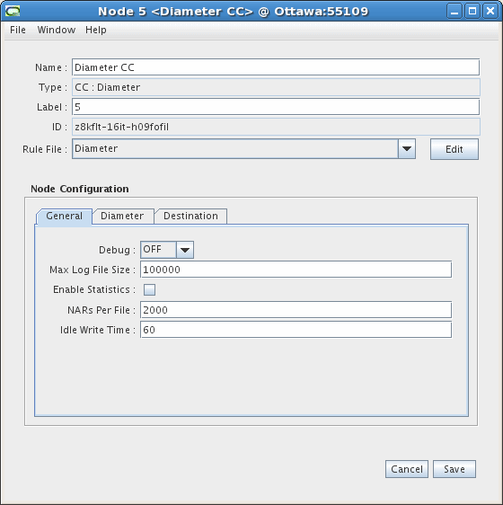
Description of the illustration ims_diameter_cc_1.gif
-
-
On the Diameter tab, accept the default field values or make changes where necessary. The field definitions are as follows:
-
Receive Port - The port that the node monitors for incoming Diameter connections.
-
Request Timer - The amount of time, in seconds, the node waits for Diameter records to be transferred during an established connection before disconnecting from the remote device.
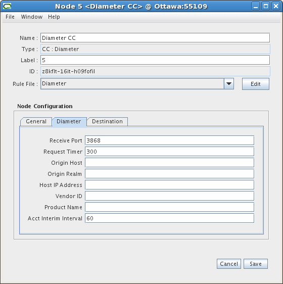
Description of the illustration ims_diameter_cc_2.gif
-
-
You do not need to configure any settings on the Destinations tab.
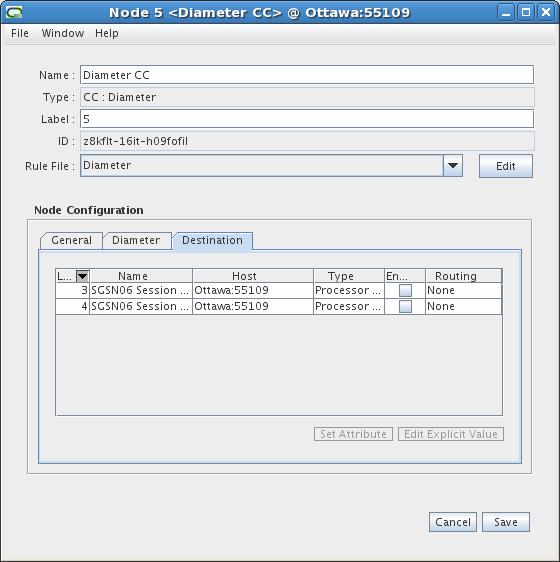
Description of the illustration ims_diameter_cc_3.gif
-
Click Save.
Creating and Configuring the Diameter Parser EP
The Diameter Parser EP receives raw diameter data from the CC and converts that data into diameter types, then sends the data to the next node in the chain, the Session Sequencing EP.
To create and configure the Diameter Parser EP:
-
Log on to Offline Mediation Controller Administration Client.
The Node Hosts & Nodes (logical view) screen appears.
-
In the Mediation Hosts table, select a host.
-
In the Nodes on Mediation Host section, click New.
The Create a Node dialog box appears.
-
Select the Wireless service solution and click Next.
-
Select Enhancement Processor (EP) and click Next.
-
Select Diameter Parser and click Finish.
-
In the node configuration window, enter a name for the node and accept the default rule file.
-
On the General tab, accept the default field values or make changes where necessary. The General tab contains generic settings that are applicable to all collection cartridges in Offline Mediation Controller. The field definitions are as follows:
-
Debug Level - Each node produces a separate log file in addition to the administration server and node manager log files. This setting allows you to control the verbosity of the debug messages generated and logged by the node.
-
Max Log File Size - This field allows you to control how large each log file will get before the node closes the file and opens a new one.
-
Read Timer - The amount of time, in seconds, that the node waits before checking for incoming data. The minimum value is 1 and the maximum value is 3600.
-
NARs per File - This setting determines how many Network Accounting Records (NARs) the node collects before sending the files to the next node in the chain.
-
Idle Write Time - If a cartridge has been idle for the amount of time (in seconds) specified here, it will automatically transmit any NARs that it has previously generated.
-
Backup NAR Files - If you select this checkbox, the cartridge will backup each NAR it has processed.
-
NAR File Retention Period - If you select the Backup NAR Files checkbox, then this field becomes active and you can enter the number of days to retain the backed up NAR files.
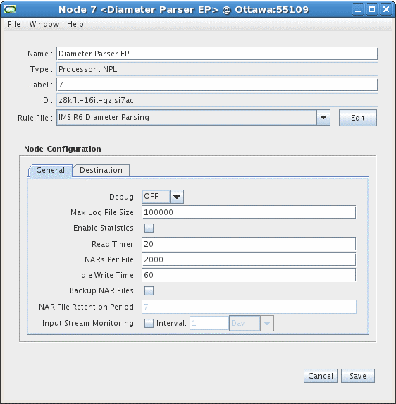
Description of the illustration ims_diameter_ep_1.gif
-
-
You do not need to configure any settings on the Destinations tab.
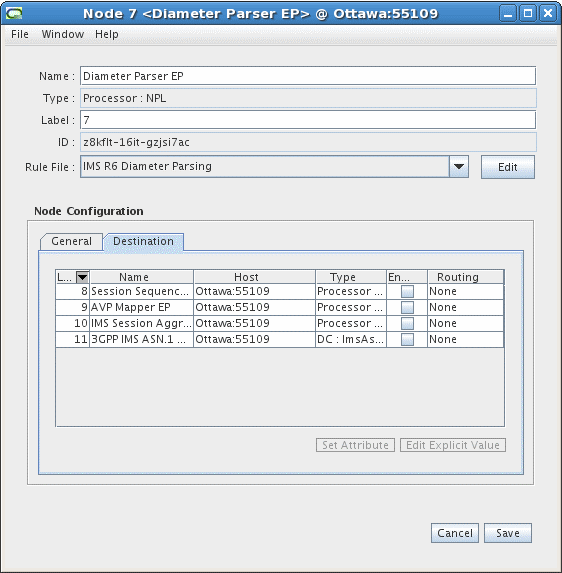
Description of the illustration ims_diameter_ep_2.gif
-
Click Save.
Creating and Configuring the Session Sequencing EP
The Session Sequencing EP organizes CDRs into the correct chronological sequence and removes duplicate records. The EP then passes the files to the next node in the chain, the AVP Mapper EP.
Note:
You must configure two Session Sequencing EPs - follow the procedure below, and for the first EP, select the IMS R6 Event De-Duplication rule file, and for the second EP, select the IMS R6 Sequence Processing rule file.To create and configure the Session Sequencing EP:
-
Log on to Offline Mediation Controller Administration Client.
The Node Hosts & Nodes (logical view) screen appears.
-
In the Mediation Hosts table, select a host.
-
In the Nodes on Mediation Host section, click New.
The Create a Node dialog box appears.
-
Select the Wireless service solution and click Next.
-
Select Enhancement Processor (EP) and click Next.
-
Select Session Sequencing and click Finish.
-
In the node configuration window, enter a name for the node and select the IMS R6 Event De-Duplication or the IMS R6 Sequence Processing rule file, depending on whether this is the first EP or the second one you are creating.
-
On the General tab, accept the default field values or make changes where necessary. The General tab contains generic settings that are applicable to all collection cartridges in Offline Mediation Controller. The field definitions are as follows:
-
Debug Level - Each node produces a separate log file in addition to the administration server and node manager log files. This setting allows you to control the verbosity of the debug messages generated and logged by the node.
-
Max Log File Size - This field allows you to control how large each log file will get before the node closes the file and opens a new one.
-
Read Timer - The amount of time, in seconds, that the node waits before checking for incoming data. The minimum value is 1 and the maximum value is 3600.
-
NARs per File - This setting determines how many Network Accounting Records (NARs) the node collects before sending the files to the next node in the chain.
-
Idle Write Time - If a cartridge has been idle for a specified amount of time (in seconds), it will automatically transmit any NARs previously generated.
-
Backup NAR Files - If you select this checkbox, the cartridge will backup each NAR it has processed.
-
NAR File Retention Period - If you select the Backup NAR Files checkbox, then this field becomes active and you can enter the number of days to retain the backed up NAR files.
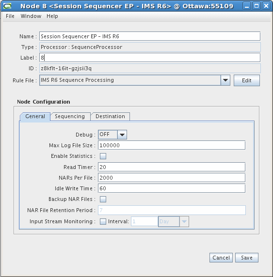
Description of the illustration ims_ss_ep_1.gif
-
-
On the Sequencing tab, accept the default field values or make changes where necessary. The field definitions are as follows:
-
Expiry Interval (minutes) - The amount of time, in minutes, the node waits for out-of-sequence records before sending any received records to the next node in the chain.
-
Log Duplicate Entries - Select this optional checkbox if you want the node to create a log entry for each duplicate record.
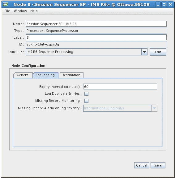
Description of the illustration ims_ss_ep_2.gif
-
-
You do not need to configure any settings on the Destinations tab.
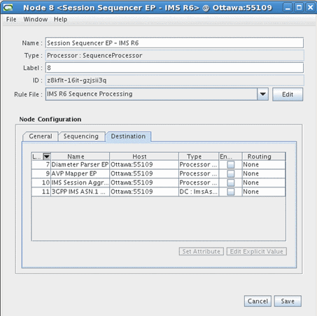
Description of the illustration ims_ss_ep_3.gif
-
Click Save.
Creating and Configuring the AVP Mapper EP
The AVP Mapper EP is responsible for converting the incoming Diameter AVPs into their equivalent 32.298 ASN.1 format. See "Output Specification" for the exact mapping of Diameter AVP to ASN.1 fields.
To create and configure the AVP Mapper EP:
-
Log on to Offline Mediation Controller Administration Client.
The Node Hosts & Nodes (logical view) screen appears.
-
In the Mediation Hosts table, select a host.
-
In the Nodes on Mediation Host section, click New.
The Create a Node dialog box appears.
-
Select the Wireless service solution and click Next.
-
Select Enhancement Processor (EP) and click Next.
-
Select AVP Mapper and click Finish.
-
In the node configuration window, enter a name for the node and accept the default rule file.
-
On the General tab, accept the default field values or make changes where necessary. The General tab contains generic settings that are applicable to all collection cartridges in Offline Mediation Controller. The field definitions are as follows:
-
Debug Level - Each node produces a separate log file in addition to the administration server and node manager log files. This setting allows you to control the verbosity of the debug messages generated and logged by the node.
-
Max Log File Size - This field allows you to control how large each log file will get before the node closes the file and opens a new one.
-
Read Timer - The amount of time, in seconds, that the node waits before checking for incoming data. The minimum value is 1 and the maximum value is 3600.
-
NARs per File - This setting determines how many Network Accounting Records (NARs) the node collects before sending the files to the next node in the chain.
-
Idle Write Time - If a cartridge has been idle for the amount of time specified here (in seconds), it will automatically transmit the NARs previously generated.
-
Backup NAR Files - If you select this checkbox, the cartridge will backup each NAR it has processed.
-
NAR File Retention Period - If you select the Backup NAR Files checkbox, then this field becomes active and you can enter the number of days to retain the backed up NAR files.
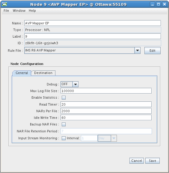
Description of the illustration ims_avp_mapper_ep_1.gif
-
-
You do not need to configure any settings on the Destinations tab.
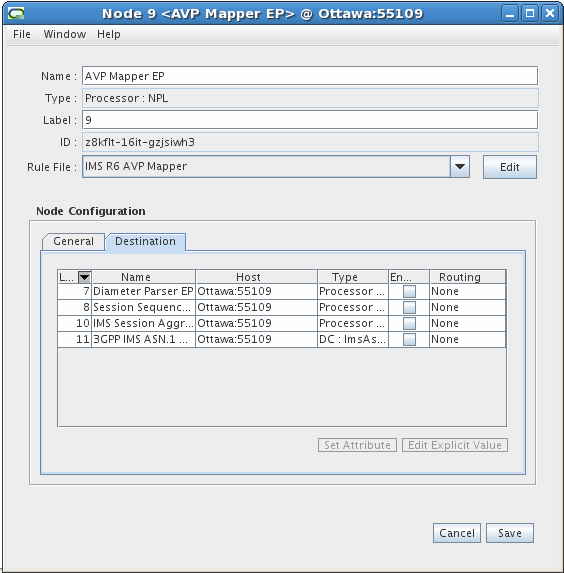
Description of the illustration ims_avp_mapper_ep_2.gif
-
Click Save.
Creating and Configuring the IMS Session Aggregation AP
The IMS Session Aggregation AP is responsible for compiling record sessions, and passing these files on to the 3GPP IMS ASN.1 DC.
To create and configure the IMS Session Aggregation AP:
-
Log on to Offline Mediation Controller Administration Client.
The Node Hosts & Nodes (logical view) screen appears.
-
In the Mediation Hosts table, select a host.
-
In the Nodes on Mediation Host section, click New.
The Create a Node dialog box appears.
-
Select the Wireless service solution and click Next.
-
Select Aggregation Processor (AP) and click Next.
-
Select Session Aggregation for IMS and click Finish.
-
In the node configuration window, enter a name for the node and accept the default rule file.
-
On the General tab, accept the default field values or make changes where necessary. The General tab contains generic settings that are applicable to all collection cartridges in Offline Mediation Controller. The field definitions are as follows:
-
Debug Level - Each node produces a separate log file in addition to the administration server and node manager log files. This setting allows you to control the verbosity of the debug messages generated and logged by the node.
-
Max Log File Size - This field allows you to control how large each log file will get before the node closes the file and opens a new one.
-
Read Timer - The amount of time, in seconds, that the node waits before checking for incoming data. The minimum value is 1 and the maximum value is 3600.
-
NARs per File - This setting determines how many Network Accounting Records (NARs) the node collects before sending the files to the next node in the chain.
-
Idle Write Time - If a cartridge has been idle for a specific amount of time (in seconds), it will automatically transmit any NARs previously generated.
-
Backup NAR Files - If you select this checkbox, the cartridge will backup each NAR it has processed.
-
NAR File Retention Period - If you select the Backup NAR Files checkbox, then this field becomes active and you can enter the number of days to retain the backed up NAR files.
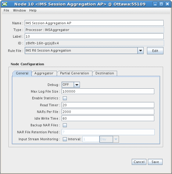
Description of the illustration ims_session_ap_1.gif
-
-
On the Aggregator tab, accept the default field values or make changes where necessary. The field definitions are as follows:
-
Flush Time - The interval, in seconds, at which the node sends aggregated NARs to the next node in the chain. The recommended configuration for the Flush Time is twice the configured Expiry Interval on the Session Sequencing EP. In addition, the Flush Time value should be higher than the configured Interim Accounting value on the CSCF as to avoid premature generation of CDRs.
-
Compression Threshold - The number of stale records the node allows before compressing the aggregation table.
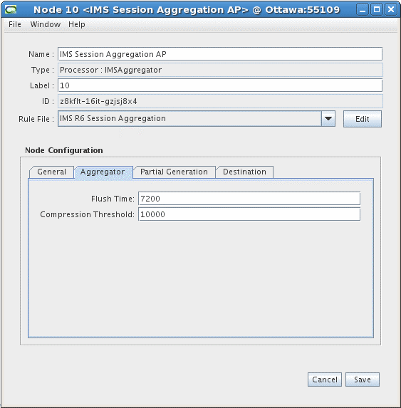
Description of the illustration ims_session_ap_2.gif
-
-
On the Partial Generation tab, you can modify or accept the default field value for the Partial Interval field, which is the time in minutes the node waits before generating a partial CDR.
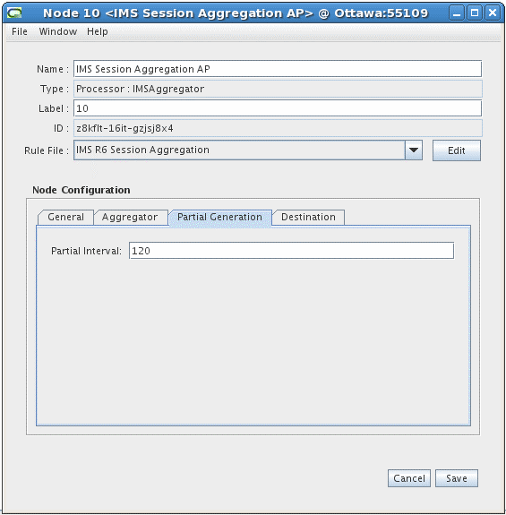
Description of the illustration ims_session_ap_3.gif
-
You do not need to configure any settings on the Destinations tab.
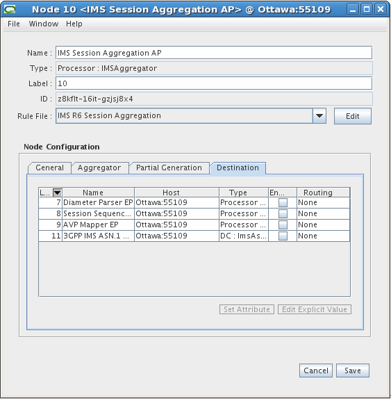
Description of the illustration ims_session_ap_4.gif
-
Click Save.
Creating and Configuring the 3GPP IMS ASN.1 DC
The 3GPP IMS ASN.1 DC converts the files it receives to ASN.1 format and then outputs the files to a downstream system.
To create and configure the 3GPP IMS ASN.1 DC:
-
Log on to Offline Mediation Controller Administration Client.
The Node Hosts & Nodes (logical view) screen appears.
-
In the Mediation Hosts table, select a host.
-
In the Nodes on Mediation Host section, click New.
The Create a Node dialog box appears.
-
Select the Wireless service solution and click Next.
-
Select Distribution Cartridge (DC) and click Next.
-
Select 3GPP IMS ASN.1 and click Finish.
-
In the node configuration window, enter a name for the node and select IMS R10.5 ASN.1 CDR for 3GPP TS V32.298 10.5.0 or IMS R6 ASN.1 CDR for 3GPP TS V32.298 6.3.0 from the Rule File list.
-
On the General tab, accept the default field values or make changes where necessary. The General tab contains generic settings that are applicable to all collection cartridges in Offline Mediation Controller. The field definitions are as follows:
-
Debug Level - Each node produces a separate log file in addition to the administration server and node manager log files. This setting allows you to control the verbosity of the debug messages generated and logged by the node.
-
Max Log File Size - This field allows you to control how large each log file will get before the node closes the file and opens a new one.
-
Read Timer - The amount of time, in seconds, that the node waits before checking for incoming data. The minimum value is 1 and the maximum value is 3600.
-
NARs per File - This setting determines how many Network Accounting Records (NARs) the node collects before sending the files to the next node in the chain.
-
Idle Write Time - If a cartridge has been idle for the amount of time (in seconds) specified it will automatically transmit the NARs previously generated.
-
Backup NAR Files - If you select this checkbox, the cartridge will backup each NAR it has processed.
-
NAR File Retention Period - If you select the Backup NAR Files checkbox, then this field becomes active and you can enter the number of days to retain the backed up NAR files.
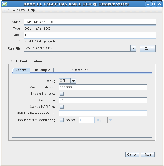
Description of the illustration ims_asn_dc_1.gif
-
-
On the File Output tab, accept the default field values or make changes where necessary. The field definitions are as follows:
-
Output Directory - Directory path to the location where Offline Mediation Controller stores the files produced by the DC.
-
File Name - The output file name.
-
Current File Extension - The file extension of the active file the node is currently processing.
-
Processed File Extension - The file extension of the file the node has finished processing.
-
Output Push Time Unit - The time unit the node uses to output processed files. Select a value from the drop-down list.
-
Output Push Time Period - Enter a numerical value that determines the time period the node uses to output processed files.
-
Max Records Per File - The maximum number of records per output file.
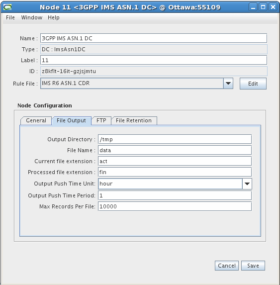
Description of the illustration ims_asn_dc_2.gif
-
-
On the FTP tab, accept the default field settings or make changes where necessary. The FTP tab allows you to specify the details of the destination application that the node transfers files to. The field definitions are as follows:
-
Use FTP - Select this checkbox if you want the node to use FTP to transfer files to the remote device.
-
FTP Host - Enter the IP address of the remote device.
-
FTP Port - Enter the port number on the remote device that the node will use to establish a connection.
-
FTP Login - Enter the login name for the remote device.
-
Remote FTP Password - Enter the password for the remote device.
-
Remote Directory - The directory on the remote device the node will transfer files to.
-
Transferred File Extension - The file extension the node applies to the processed files in the local storage directory after it successfully transfers the files to the remote device.
-
FTP Interval - The amount of time the node waits between file transfers to the remote device.
-
Use SFTP - Select this checkbox if you want the node to use secure FTP when transferring files.
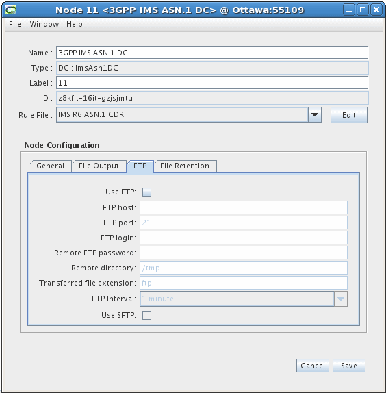
Description of the illustration ims_asn_dc_3.gif
-
-
On the File Retention tab, configure the desired settings:
-
Enable Output File Archive/Delete - Select this box to enable the capability to archive or delete the AMA data after it has been retrieved by the downstream billing software.
-
Retention Period (in Days) - The delete or archive actions are done after a defined number of days. The allowable range is 1 to 60 days.
-
Delete Output File - Select this option to delete the output file after the configured number of days.
-
Archive File to Directory - Select this option to archive the output file after the configured number of days. Accept the default directory location or type in a different directory location.
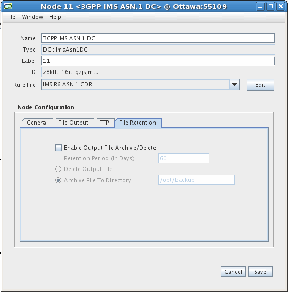
Description of the illustration ims_asn_dc_4.gif
-
-
Click Save.
IMS Sample Output
This section lists the IMS sample outputs.
Sample 1
The following is IMS sample output from an S-CSCF record in 32.298 ASN.1 format, converted to readable text.
* * * * * * * Record 1 * * * * * * *
32.298 v 10.5.0 IMS CDR
------------------
value IMSRecord ::= sCSCFRecord : {
  recordType sCSCFRecord,
  role-of-Node terminating,
  nodeAddress domainName : "cscf.nn.com",
  session-Id "5e5e-0884-39f4-bb1e6e62@47.129.74.198",
  list-Of-Calling-Party-Address {
    sIP-URI : "sip:004nigelfull@di.com"
  },
  called-Party-Address tEL-URI : "10.13.4.3",
  privateUserID "004nigelfullprv@di.com",
  serviceRequestTimeStamp '0501280850512B0000'H,
  serviceDeliveryStartTimeStamp '0501280850542B0000'H,
  recordOpeningTime '1203190334362B0000'H,
  recordClosureTime '1203190334362B0000'H,
  interOperatorIdentifiers {
    {
      originatingIOI "nigel.com",
      terminatingIOI "nigel.com"
    }
  },
  localRecordSequenceNumber 0,
  causeForRecordClosing timeLimit,
  incomplete-CDR-Indication {
    aCRStartLost FALSE,
    aCRInterimLost unknown,
    aCRStopLost TRUE
  },
  iMS-Charging-Identifier '3133355F313130363933323335373434364034372E3234382E36372E3433'H,
  list-Of-SDP-Media-Components {
    {
      sIP-Request-Timestamp '0501280850512B0000'H,
      sIP-Response-Timestamp '0501280850542B0000'H,
      sDP-Media-Components {
        {
          sDP-Media-Name "Video Conference",
          sDP-Media-Descriptions {
            "a=video conference"
          },
          authorized-QoS "Gold"
        }
      },
      mediaInitiatorFlag NULL,
      sDP-Session-Description {
        "a=Video Conference"
      },
      sIP-Request-Timestamp-Fraction 123456,
      sIP-Response-Timestamp-Fraction 234567,
      sDP-Type sDP-offer,
      localGWInsertedIndication TRUE,
      iPRealmDefaultIndication TRUE,
      transcoderInsertedIndication TRUE
    }
  },
  gGSNaddress iPAddress : iPBinaryAddress : iPBinV4Address : '0A0D05E0'H,
  serviceReasonReturnCode "-302",
  list-Of-Message-Bodies {
    {
      content-Type "application/sdp",
      content-Disposition "Disposition",
      content-Length 3420720,
      originator sIP-URI : "2"
    }
  },
  expiresInformation 12345,
  accessNetworkInformation '4163636573734E6574776F726B496E666F726D6174696F6E'H,
  serviceContextID "MNC.MCC.11.32260@3gpp.org",
  list-of-subscription-ID {
    {
      subscriptionIDType eND-USER-IMSI,
      subscriptionIDData "SubscriptionIdData1"
    }
  },
  list-Of-Early-SDP-Media-Components {
    {
      sDP-Media-Components {
        {
          sDP-Media-Name "Video Conference 1",
          sDP-Media-Descriptions {
            "sdp media description- video conference"
          },
          authorized-QoS "Gold"
    }
     },
      mediaInitiatorFlag NULL,
      sDP-Session-Description {
        "a=my sdp session description 1"
      },
      sDP-Type sDP-offer
    }
  },
  iMSCommunicationServiceIdentifier '496D73436F6D6D5376634964'H,
  numberPortabilityRouting "DataForNPRI",
  carrierSelectRouting "DataForCSRI",
  sessionPriority pRIORITY-1,
  serviceRequestTimeStampFraction 123456,
  serviceDeliveryStartTimeStampFraction 234567,
  applicationServersInformation {
    {
      applicationServersInvolved domainName : "sip:47.135.114.225:5060",
      applicationProvidedCalledParties {
        sIP-URI : "10.13.5.91"
      }
    }
  },
  requested-Party-Address tEL-URI : "RequestedPartyAddress",
  list-Of-Called-Asserted-Identity {
    sIP-URI : "sip:Called-Asserted-Identity-1"
  },
  online-charging-flag NULL,
  realTimeTariffInformation {
    tariffInformation : {
      currencyCode 840,
      scaleFactor { mantissa 3075, base 2, exponent 2 },
      rateElements {
        {
          unitType 1,
          unitValue { mantissa 3075, base 2, exponent 2 },
          unitCost { mantissa 3075, base 2, exponent 2 },
          unitQuotaThreshold { mantissa 105, base 2, exponent 1 }
        }
      }
    }
  }
}
Sample 2
The following is IMS sample output from a P-CSCF record in 32.298 ASN.1 format, converted to readable text.
* * * * * * * Record 1 * * * * * * *
32.298 v 10.5.0 IMS CDR
------------------
value IMSRecord ::= pCSCFRecord : {
  recordType pCSCFRecord,
  role-of-Node terminating,
  nodeAddress domainName : "cscf.nn.com",
  session-Id "5e5e-0884-39f4-bb1e6e62@47.129.74.198",
  list-Of-Calling-Party-Address {
    sIP-URI : "sip:004nigelfull@di.com"
  },
  called-Party-Address tEL-URI : "10.13.4.3",
  serviceRequestTimeStamp '0501280850512B0000'H,
  serviceDeliveryStartTimeStamp '0501280850542B0000'H,
  recordOpeningTime '1203210136242B0000'H,
  recordClosureTime '1203210136242B0000'H,
  interOperatorIdentifiers {
    originatingIOI "nigel.com",
    terminatingIOI "nigel.com"
  },
  localRecordSequenceNumber 1,
  causeForRecordClosing timeLimit,
  incomplete-CDR-Indication {
    aCRStartLost FALSE,
    aCRInterimLost unknown,
    aCRStopLost TRUE
  },
  iMS-Charging-Identifier '3133355F313130363933323335373434364034372E3234382E36372E3433'H,
  list-Of-SDP-Media-Components {
    {
      sIP-Request-Timestamp '0501280850512B0000'H,
      sIP-Response-Timestamp '0501280850542B0000'H,
      sDP-Media-Components {
        {
          sDP-Media-Name "Video Conference",
          sDP-Media-Descriptions {
            "a=video conference"
          },
          authorized-QoS "Gold"
        }
      },
      mediaInitiatorFlag NULL,
      sDP-Session-Description {
        "a=Video Conference"
      },
      sIP-Request-Timestamp-Fraction 123456,
      sIP-Response-Timestamp-Fraction 234567,
      sDP-Type sDP-offer,
      localGWInsertedIndication TRUE,
      iPRealmDefaultIndication TRUE,
      transcoderInsertedIndication TRUE
    }
  },
  gGSNaddress iPAddress : iPBinaryAddress : iPBinV4Address : '0A0D05E0'H,
  serviceReasonReturnCode "-302",
  list-Of-Message-Bodies {
    {
      content-Type "application/sdp",
      content-Disposition "Disposition",
      content-Length 3420720,
      originator sIP-URI : "2"
    }
  },
  expiresInformation 12345,
  accessNetworkInformation '4163636573734E6574776F726B496E666F726D6174696F6E'H,
  list-of-subscription-ID {
    {
      subscriptionIDType eND-USER-SIP-URI,
      subscriptionIDData "SubscriptionIdData"
    }
  },
  list-Of-Early-SDP-Media-Components {
    {
      sDP-Media-Components {
        {
          sDP-Media-Name "Video Conference 1",
          sDP-Media-Descriptions {
            "sdp media description- video conference"
          },
          authorized-QoS "Gold"
        }
      },
      mediaInitiatorFlag NULL,
      sDP-Session-Description {
     },
      sDP-Type sDP-offer
    }
  },
  iMSCommunicationServiceIdentifier '496D73436F6D6D5376634964'H,
  sessionPriority pRIORITY-1,
  serviceRequestTimeStampFraction 123456,
  serviceDeliveryStartTimeStampFraction 234567,
  list-Of-Called-Asserted-Identity {
    tEL-URI : "CalledAsserterQuantity1"
  },
  iMSApplicationReferenceIdentifer '496D734170705265664964'H
}