| Oracle® Big Data Appliance Owner's Guide Release 1 (1.0.3) Part Number E25960-05 |
|
|
PDF · Mobi · ePub |
| Oracle® Big Data Appliance Owner's Guide Release 1 (1.0.3) Part Number E25960-05 |
|
|
PDF · Mobi · ePub |
The tables in this appendix show the cable connections for Oracle Big Data Appliance. This appendix contains the following sections:
The cables used in Oracle Big Data Appliance are color-coded as follows:
Black: InfiniBand cables or AC power jumper cables
Red: Integrated Lights Out Management (Oracle ILOM) Ethernet management cables
Blue: Gigabit Ethernet management (eth0) cables
Orange: KVM switch to dongle cables
Figure B-1 shows the front and rear layout of an Oracle Big Data Appliance rack.
Figure B-1 Rack Layout of Oracle Big Data Appliance
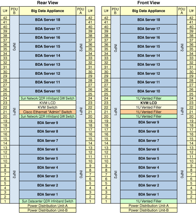
Table B-1 shows the keyboard, video, and mouse (KVM) network cabling. The KVM port on the servers is labeled SER MGT and connects to the KVM switch located in rack unit 22.
Table B-1 KVM Cabling for an Oracle Big Data Appliance Rack
| From Rack UnitFoot 1 | Port | To KVM Port | Cable Length | Cable Color | Component |
|---|---|---|---|---|---|
|
U41 |
Net-0 |
1 |
10 feet |
Black |
Server Cell 18 |
|
U39 |
Net-0 |
3 |
10 feet |
Black |
Server Cell 17 |
|
U37 |
Net-0 |
5 |
10 feet |
Black |
Server Cell 16 |
|
U35 |
Net-0 |
7 |
10 feet |
Black |
Server Cell 15 |
|
U33 |
Net-0 |
9 |
10 feet |
Black |
Server Cell 14 |
|
U31 |
Net-0 |
11 |
10 feet |
Black |
Server Cell 13 |
|
U29 |
Net-0 |
13 |
10 feet |
Black |
Server Cell 12 |
|
U27 |
Net-0 |
17 |
10 feet |
Black |
Server Cell 11 |
|
U25 |
Net-0 |
21 |
10 feet |
Black |
Server Cell 10 |
|
U24 |
Net-0 |
45 |
10 feet |
Black |
NM2-1B Switch |
|
U20 |
Net-0 |
46 |
10 feet |
Black |
NM2-1B Switch |
|
U18 |
Net-0 |
25 |
10 feet |
Black |
Server Cell 9 |
|
U16 |
Net-0 |
29 |
10 feet |
Black |
Server Cell 8 |
|
U14 |
Net-0 |
31 |
10 feet |
Black |
Server Cell 7 |
|
U12 |
Net-0 |
33 |
10 feet |
Black |
Server Cell 6 |
|
U10 |
Net-0 |
35 |
10 feet |
Black |
Server Cell 5 |
|
U8 |
Net-0 |
37 |
10 feet |
Black |
Server Cell 4 |
|
U6 |
Net-0 |
39 |
10 feet |
Black |
Server Cell 3 |
|
U4 |
Net-0 |
41 |
10 feet |
Black |
Server Cell 2 |
|
U2 |
Net-0 |
43 |
10 feet |
Black |
Server Cell 1 |
|
U1 |
Net-0 |
47 |
10 feet |
Black |
NM2-1B Switch |
|
PDU-A |
Net Mgt |
15 |
1 meter |
White |
PDU-A |
|
PDU-B |
Net Mgt |
19 |
1 meter |
White |
PDU-B |
|
NAFoot 2 |
NA |
48 |
10 feet |
Blue |
Service |
Footnote 1 Un is the unit location in the rack, where n is the number.
Footnote 2 Not applicable.
Table B-2 shows the cable connections from the servers to the Oracle ILOM switch. The Oracle ILOM port on the servers is labeled NET MGT and connects to the Cisco Ethernet switch located in rack unit 21. The cables are red and 10 feet long.
| From Rack UnitFoot 1 | Ethernet Port | Component |
|---|---|---|
|
U41 |
2 |
Server Cell 18 |
|
U39 |
4 |
Server Cell 17 |
|
U37 |
6 |
Server Cell 16 |
|
U35 |
8 |
Server Cell 15 |
|
U33 |
10 |
Server Cell 14 |
|
U31 |
12 |
Server Cell 13 |
|
U29 |
14 |
Server Cell 12 |
|
U27 |
18 |
Server Cell 11 |
|
U25 |
22 |
Server Cell 10 |
|
U18 |
26 |
Server Cell 9 |
|
U16 |
30 |
Server Cell 8 |
|
U14 |
32 |
Server Cell 7 |
|
U12 |
34 |
Server Cell 6 |
|
U10 |
36 |
Server Cell 5 |
|
U8 |
38 |
Server Cell 4 |
|
U6 |
40 |
Server Cell 3 |
|
U4 |
42 |
Server Cell 2 |
|
U2 |
44 |
Server Cell 1 |
Footnote 1 Un is the unit location in the rack, where n is the number.
Table B-3 shows the connections for single-phase cabling from each power distribution unit (PDU) to the power supplies in the rack. The cables terminate at PDU-A on the left and are routed to the right to enter the cable management arm (CMA). The cables are bundled in groups of four.
Table B-3 Single-Phase PDU Cabling
| Rack UnitFoot 1 | PDU-A/PS-00 | PDU-B/PS-01 | Cable Length | Component |
|---|---|---|---|---|
|
U41 |
G5-6 |
G0-0 |
2 meters |
Server |
|
U39 |
G5-3 |
G0-3 |
2 meters |
Server |
|
U37 |
G5-0 |
G0-6 |
2 meters |
Server |
|
U35 |
G4-6 |
G1-0 |
2 meters |
Server |
|
U33 |
G4-4 |
G1-2 |
2 meters |
Server |
|
U31 |
G4-2 |
G1-4 |
2 meters |
Server |
|
U29 |
G3-6 |
G2-0 |
2 meters |
Server |
|
U27 |
G3-5 |
G2-1 |
2 meters |
Server |
|
U25 |
G3-3 |
G2-3 |
2 meters |
Server |
|
U24 |
G3-1 |
G2-5 |
2 meters |
NM2 |
|
U23 |
NAFoot 2 |
G3-0 |
included |
KVM |
|
U22 |
G2-5 |
G3-1 |
1 meter |
KVM tray |
|
U21 |
G3-0 |
G2-6 |
2 meters |
Cisco switch |
|
U20 |
G2-4 |
G3-2 |
2 meters |
NM2 |
|
U18 |
G2-2 |
G3-4 |
2 meters |
Server |
|
U16 |
G1-6 |
G4-0 |
2 meters |
Server |
|
U14 |
G2-0 |
G3-6 |
2 meters |
Server |
|
U12 |
G1-4 |
G4-2 |
2 meters |
Server |
|
U10 |
G1-2 |
G4-4 |
2 meters |
Server |
|
U8 |
G1-0 |
G4-6 |
2 meters |
Server |
|
U6 |
G0-6 |
G5-0 |
2 meters |
Server |
|
U4 |
G0-4 |
G5-2 |
2 meters |
Server |
|
U2 |
G0-2 |
G5-4 |
2 meters |
Server |
|
U1 |
G0-0 |
G5-6 |
2 meters |
NM2 |
Footnote 1 Un is the unit location in the rack, where n is the number.
Footnote 2 Not applicable.
Table B-4 describes three-phase cabling from each power distribution unit (PDU) to the power supplies in the servers. The cables are terminated to PDU-A on the left, are routed to the right to enter CMA, and are bundled in groups of four.
Table B-4 Three-Phase PDU Cabling
| Rack UnitFoot 1 | PDU-A/PS-00 | PDU-B/PS-01 | Cable Length | Component |
|---|---|---|---|---|
|
U41 |
G5-6 |
G2-0 |
2 meters |
Server |
|
U39 |
G5-3 |
G2-3 |
2 meters |
Server |
|
U37 |
G5-0 |
G2-6 |
2 meters |
Server |
|
U35 |
G4-6 |
G1-0 |
2 meters |
Server |
|
U33 |
G4-4 |
G1-2 |
2 meters |
Server |
|
U31 |
G4-2 |
G1-4 |
2 meters |
Server |
|
U29 |
G3-6 |
G0-0 |
2 meters |
Server |
|
U27 |
G3-5 |
G0-1 |
2 meters |
Server |
|
U25 |
G3-3 |
G0-3 |
2 meters |
Server |
|
U24 |
G3-1 |
G0-5 |
2 meters |
NM2 |
|
U23 |
NAFoot 2 |
G0-3 |
included |
KVM |
|
U22 |
G2-5 |
G5-1 |
1 meter |
KVM tray |
|
U21 |
G3-0 |
G0-6 |
2 meters |
Cisco |
|
U20 |
G2-4 |
G5-2 |
2 meters |
NM2 |
|
U18 |
G2-2 |
G5-4 |
2 meters |
Server |
|
U16 |
G4-2 |
G5-2 |
2 meters |
Server |
|
U14 |
G2-0 |
G5-6 |
2 meters |
Server |
|
U12 |
G1-4 |
G4-2 |
2 meters |
Server |
|
U10 |
G1-2 |
G4-4 |
2 meters |
Server |
|
U8 |
G1-0 |
G4-6 |
2 meters |
Server |
|
U6 |
G0-6 |
G3-0 |
2 meters |
Server |
|
U4 |
G0-4 |
G3-2 |
2 meters |
Server |
|
U2 |
G0-2 |
G3-4 |
2 meters |
Server |
|
U1 |
G0-0 |
G3-6 |
2 meters |
NM2 |
Footnote 1 Un is the unit location in the rack, where n is the number.
Footnote 2 Not applicable.
Table B-5 lists the location, ports, and cables for the InfiniBand connections from switch to switch. Figure B-2 identifies the locations of the ports on a Sun Network QDR InfiniBand Gateway Switch.
Table B-5 InfiniBand Switch-to-Switch Cabling
| From InfiniBand Switch Rack UnitFoot 1 | Port | To InfiniBand Switch Rack UnitFootref 1 | Port | Cable Length | Description |
|---|---|---|---|---|---|
|
U20 |
9B |
U24 |
9A |
2 meters |
Leaf to leaf |
|
U20 |
10B |
U24 |
10A |
2 meters |
Leaf to leaf |
|
U20 |
11B |
U24 |
11A |
2 meters |
Leaf to leaf |
|
U20 |
8A |
U24 |
8A |
2 meters |
Leaf to leaf |
|
U20 |
9A |
U24 |
9B |
2 meters |
Leaf to leaf |
|
U20 |
10A |
U24 |
10B |
2 meters |
Leaf to leaf |
|
U20 |
11A |
U24 |
11B |
2 meters |
Leaf to leaf |
|
U1 |
0B |
U24 |
8B |
3 meters |
Spine to leaf |
|
U1 |
1B |
U20 |
8B |
3 meters |
Spine to leaf |
Footnote 1 Un is the unit location in the rack, where n is the number.
Figure B-2 Sun Network QDR InfiniBand Gateway Switch Ports
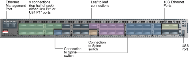
Table B-6 lists the location, ports and cables for the InfiniBand connections from switch to server.
Table B-6 InfiniBand Switch-to-Server Cabling
| From InfiniBand Switch Rack UnitFoot 1 | Port | To Rack UnitFootref 1 | PortFoot 2 | Cable Length |
|---|---|---|---|---|
|
U24 |
0A |
U41 |
PCIe 3 P1 |
3 meters |
|
U24 |
0B |
U39 |
PCIe 3 P1 |
3 meters |
|
U24 |
1A |
U37 |
PCIe 3 P1 |
3 meters |
|
U24 |
1B |
U35 |
PCIe 3 P1 |
3 meters |
|
U24 |
2A |
U33 |
PCIe 3 P1 |
3 meters |
|
U24 |
2B |
U31 |
PCIe 3 P1 |
3 meters |
|
U24 |
3A |
U29 |
PCIe 3 P1 |
3 meters |
|
U24 |
3B |
U27 |
PCIe 3 P1 |
2 meters |
|
U24 |
4A |
U25 |
PCIe 3 P1 |
2 meters |
|
U20 |
0A |
U41 |
PCIe 3 P2 |
3 meters |
|
U20 |
0B |
U39 |
PCIe 3 P2 |
3 meters |
|
U20 |
1A |
U37 |
PCIe 3 P2 |
3 meters |
|
U20 |
1B |
U35 |
PCIe 3 P2 |
3 meters |
|
U20 |
2A |
U33 |
PCIe 3 P2 |
3 meters |
|
U20 |
2B |
U31 |
PCIe 3 P2 |
3 meters |
|
U20 |
3A |
U29 |
PCIe 3 P2 |
3 meters |
|
U20 |
3B |
U27 |
PCIe 3 P2 |
2 meters |
|
U20 |
4A |
U25 |
PCIe 3 P2 |
2 meters |
|
U20 |
4B |
U18 |
PCIe 3 P2 |
2 meters |
|
U20 |
12A |
U16 |
PCIe 3 P2 |
2 meters |
|
U20 |
12B |
U14 |
PCIe 3 P1 |
2 meters |
|
U20 |
13A |
U12 |
PCIe 3 P1 |
2 meters |
|
U20 |
13B |
U10 |
PCIe 3 P1 |
2 meters |
|
U20 |
14A |
U8 |
PCIe 3 P1 |
2 meters |
|
U20 |
14B |
U6 |
PCIe 3 P1 |
2 meters |
|
U20 |
15A |
U4 |
PCIe 3 P1 |
3 meters |
|
U20 |
15B |
U2 |
PCIe 3 P1 |
3 meters |
|
U24 |
4B |
U18 |
PCIe 3 P1 |
2 meters |
|
U24 |
12A |
U16 |
PCIe 3 P1 |
2 meters |
|
U24 |
12B |
U14 |
PCIe 3 P2 |
2 meters |
|
U24 |
13A |
U12 |
PCIe 3 P2 |
2 meters |
|
U24 |
13B |
U10 |
PCIe 3 P2 |
2 meters |
|
U24 |
14A |
U8 |
PCIe 3 P2 |
2 meters |
|
U24 |
14B |
U6 |
PCIe 3 P2 |
3 meters |
|
U24 |
15A |
U4 |
PCIe 3 P2 |
3 meters |
|
U24 |
15B |
U2 |
PCIe 3 P2 |
3 meters |
Footnote 1 Un is the unit location in the rack, where n is the number.
Footnote 2 Pn is the InfiniBand port, where n is port number.
|
Copyright © 2012, Oracle and/or its affiliates. All rights reserved. Legal Notices |
|