JavaScript is required to for searching.
Skip Navigation Links
Exit Print View
Netra Server X3-2 HTML Document Collection
search filter icon
search icon

Document Information

Using This Documentation

Product Notes

Related Documentation

Feedback

Access to Oracle Support

Installation

Understanding the Server

Installation Task Overview

Server Overview

Front Panel Components (Installation)

Rear Panel Components (Installation)

Confirming Server and Site Specifications

Physical Specifications

Minimum Clearance for Service Access

AC and DC Power Supply Specifications

Input Power Information

Overcurrent Protection Requirements

DC Power Source, Power Connection, and Grounding Requirements

Environmental Requirements

Acoustic Noise Emissions

Airflow Clearance

Preparing for Installation

Shipping Kit Inventory

Handling Precautions

ESD Precautions

Tools Needed for Installation

Optional Components

Rack Cautions

Stabilize the Rack

Installing the Server in a 4-Post Rack

Installing the Standard 19-Inch Hardmount Kit (4-Post Rack)

Installing the 19-Inch Sliding-Rail Kit (4-Post Rack)

Installing the 600-mm Hardmount Kit (4-Post Rack)

Installing the Server in a 2-Post Rack

Installing the 19-Inch Hardmount Kit (2-Post Rack)

Installing the 19-Inch Sliding-Rail Kit (2-Post Rack)

Installing the 23-Inch Hardmount Kit (2-Post Rack)

Connecting Cables

Connecting Data and Management Cables

Identifying Ports

Powering On the Server the First Time

Connect AC Power Cords

Assembling DC Power Cords and Applying DC Power

Power On the Host for the First Time

OS Installation

Choosing an OS Installation Method

OS Installation Task Map (Oracle Solaris)

OS Installation Task Map (Oracle VM)

OS Installation Task Map (Linux)

OS Installation Task Map (VMware ESXi)

OS Installation Task Map (Windows)

Supported OS Versions and Documentation

Oracle Linux Support Kernel

Understanding Installation Methods

Configuring the Preinstalled Oracle Solaris OS

Preinstalled OS RAID Limitations

Configuration Worksheet (Oracle Solaris)

Configure the Preinstalled Oracle Solaris OS

Configuring the Preinstalled Oracle VM 3. 0 Software

Configuration Worksheet (Oracle VM Server)

Configure the Preinstalled Oracle VM 3.0 OS

Oracle VM 3.0 Overview

Preparing to Install an OS

Selecting the Console Display

Selecting the Boot Media

Preparing Your PXE Environment

Accessing Installation Utilities

Setting Up BIOS

Configuring RAID

HBA and RAID Support

RAID Configuration Requirements

Post-Installation RAID Volume Creation

Configure RAID (OSA)

Configuring RAID Volumes (LSI BIOS Utilities)

Installing a Supported OS

Install an OS (OSA)

Installing an OS (Media)

Install an OS (PXE)

Performing Post-Installation Tasks

(Optional) Assign Boot Drive Priorities

Oracle VM Post-Installation Information

Performing Linux Post-Installation Tasks

Performing VMware ESXi Post-Installation Tasks

Performing Windows Post-Installation Tasks

Administration

Understanding Administration Resources

Common Administration Tools

Oracle ILOM Overview

BIOS Overview (Administration)

OSA Overview

HMP

Hardware RAID Administration Tools

Multiple Server Management Tools

Accessing Administration Tools

Accessing Oracle ILOM

Accessing BIOS

Accessing OSA

Access Add-On Card Configuration Utilities (BIOS)

Controlling the Server

Controlling the Power State

Change Telco Alarm States Manually

Configuring Power-On and Boot Options

Configuring Power-On Policies

Selecting a Boot Device

Configuring Oracle ILOM

Change the Oracle ILOM Root Password (Oracle ILOM CLI)

Recover the Oracle ILOM Root Password

Configuring Oracle ILOM (Oracle ILOM Web Interface)

Configuring the SP and Oracle ILOM (BIOS)

Configure the SP and Oracle ILOM (OSA)

Configure the Enhanced PCIe Cooling Mode Policy (Oracle ILOM CLI)

Configuring BIOS

Resetting the BIOS to Default Settings

Configuring Legacy Option ROM Allocation

Configuring I/O Resource Allocation

Configuring Devices in BIOS

Enabling or Disabling OSA

Disable OSA

Enable OSA

Monitoring the Server

Obtain the Server Serial Number

Locate the Server (Oracle ILOM Web Interface)

Obtaining Server Information

Monitoring the Server Health (Oracle ILOM Web Interface)

Understanding SNMP Traps

Updating the Firmware and Software

Update to a New OSA Release

Obtain and Update Firmware (OSA)

Restore OSA

Mounting the Oracle System Assistant USB Flash Drive

Obtaining Updated Software

Requesting Updates on Physical Media

Service

Identifying Components

Component Locations (Storage, Power, and Fans)

Component Locations (Motherboard, Memory, and PCIe3 Cards)

Front Panel Components (Service)

Rear Panel Components (Service)

Detecting and Managing Faults

Understanding Diagnostics

Interpreting Diagnostic LEDs

Troubleshooting (Oracle ILOM /SP Targets)

BIOS POST Event Messages

Troubleshooting (Oracle ILOM /System Targets)

Displaying Faulty Components

Troubleshooting (Oracle ILOM Legacy Targets)

Troubleshooting (Pc-Check)

Preparing for Service

Safety Information

Tools Needed for Service

Filler Panels

Find the Server Serial Number

Component Service Task Reference

Locate the Server

Removing Power From the Server

Accessing Internal Components

Remove the Fan Tray

Raise the Drive Cage to the Service Position

Remove the Air Duct

Remove the PDB Duct

Servicing the Filter

Remove the Filter

Install the Filter

Servicing Drives

Drive Configuration

Drive LEDs

Locate a Faulty Drive

Remove a Drive

Install a Drive

Verify a Drive

Servicing the DVD Drive

Remove the DVD Drive

Install the DVD Drive

Servicing Power Supplies

Power Supply LEDs

Locate a Faulty Power Supply

Remove a Power Supply

Install a Power Supply

Verify a Power Supply

Servicing Fan Modules

Fan Module LEDs

Locate a Faulty Fan Module

Remove a Fan Module

Install a Fan Module

Verify a Fan Module

Servicing Risers

Riser Configuration

Locate a Faulty Riser

Remove a Riser

Install a Riser

Verify a Riser

Servicing PCIe3 Cards

PCIe3 Card Configuration

Locate a Faulty PCIe3 Card

Remove a PCIe3 Card (Risers 1 and 2)

Remove a PCIe3 Card (Riser 3)

Install a PCIe3 Card (Risers 1 and 2)

Install a PCIe3 Card (Riser 3)

Verify a PCIe3 Card

Servicing the Battery

Remove the Battery

Install the Battery

Servicing the USB Drive

USB Drive LED

Remove the USB Drive

Install the USB Drive

Servicing Cables

Cable Configuration

Remove the Drive Signal Cable

Install the Drive Signal Cable

Remove the Drive Power Cable

Install the Drive Power Cable

Remove the DVD SATA Cable

Install the DVD SATA Cable

Remove the PDB Signal Cable

Install the PDB Signal Cable

Servicing the Drive Backplane

Drive Backplane Configuration

Determine if the Drive Backplane Is Faulty

Remove the Drive Backplane

Install the Drive Backplane

Verify the Drive Backplane

Servicing DIMMs

DIMM Configuration

Locate a Faulty DIMM

Remove a DIMM

Install a DIMM

Verify a DIMM

Servicing CPUs

CPU Configuration

Locate a Faulty CPU

CPU Tool

Remove a CPU

Install a CPU

Servicing the LED Board

Determine if the LED Board Is Faulty

Remove the LED Board

Install the LED Board

Verify the LED Board

Servicing the USB Board

Remove the USB Board

Install the USB Board

Servicing the Motherboard

Determine if the Motherboard Is Faulty

Remove the Motherboard

Install the Motherboard

Verify the Motherboard

Servicing the PDB

Determine if the PDB Is Faulty

Remove the PDB

Install the PDB

Verify the PDB

Returning the Server to Operation

Install the PDB Duct

Install the Air Duct

Secure the Drive Cage

Install the Fan Tray

Install the Top Cover

Connect Power Cords

Power On the Server (Oracle ILOM)

Power On the Server (Power Button)

Glossary

Index

Remove a CPU

Removing a CPU is a cold-service operation. You must power off the server before you remove the CPU.

  1. Determine which CPU to remove.

    See Locate a Faulty CPU.

  2. Consider your next step.
    • If you have not prepared for service, do so now. See Preparing for Service.

    • If you are removing a CPU as part of another component's removal or installation procedure, go to Step 3.

  3. Review this information and complete these prerequisites in this order.
  4. Locate the CPU to remove.

    See CPU Configuration.

  5. Loosen the four captive screws of the CPU heat sink.

    Alternate between the screws in an X pattern, turning each 1 revolution, until they are fully removed.
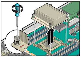

    image:The illustration shows removing the heat sink.
  6. Grasp the heat sink and wiggle it clockwise and counterclockwise while pulling up.

    This action breaks the adhesion of the heat sink to the CPU.


    Caution

    Caution - Do not pull forcibly as you might damage the heat sink or CPU socket.


  7. Use an alcohol pad to clean the thermal compound from the heat sink and CPU.

    Note - Be careful not to get the thermal compound on your fingers because this could contaminate components.
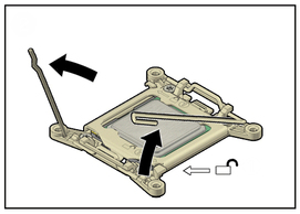
  8. Unhook the pressure frame release levers from the catches of the CPU socket and raise them upward to approximately 35 degrees.
    image:The illustration shows opening the release levers.
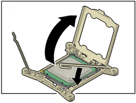
  9. Release the pressure frame by slightly lowering the right release lever and lifting the pressure frame up to the fully open position.
    image:The illustration shows opening the pressure frame.
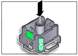
  10. Press the release button on the CPU tool.
    image:The illustration shows pressing the release button.
  11. Position the tool over the CPU socket and lower it onto the CPU.

    The triangle on the side of the tool aligns with pin 1 of the CPU.
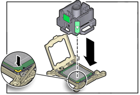

    image:The illustration shows positioning the CPU tool.
  12. Push the hold lever outward to engage the CPU.

    You hear a click, and the release button retracts.
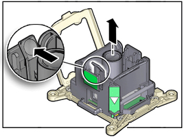

    image:The illustration shows engaging the CPU.
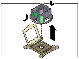
  13. Grasp the tool by its sides and lift it from the CPU socket.
    image:The illustration shows lifting the tool.
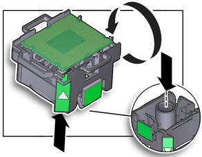
  14. While holding the tool upside down with one hand, and the CPU edges with the other hand, press the release button.
    image:The illustration shows releasing the CPU.
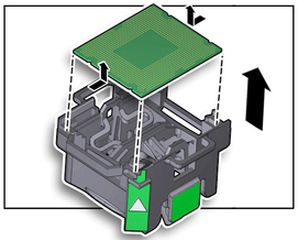
  15. Lift the CPU out of the tool and place it pin side down on an antistatic mat.
    image:The illustration shows lifting the CPU from the tool.
  16. Repeat from Step 4 for any additional CPU to be removed.
  17. Install the replacement CPU.

    See Install a CPU.

Related Information