6 Creating and Running the Integration Interface
This chapter describes how to create and run the integration interface.
It contains the following topics:
Creating the Integration Interface
Now that the ODI source and target data models have been created, it is possible to create the ODI interfaces to extract data from the following SAP BW data targets:
-
The Info Cube
0FIAP_C20data target toW_VENDR_BAL_DSOracle table. -
The Info Object
0CREDITORdata target toW_ACCNT_VENDR_DSOracle table. -
The Hierarchy data from Info Object
0GL_ACCOUNTtoW_GL_ACCOUNT_HIER_DSOracle table. -
The Interval Hierarchy data from InfoObject
0GL_ACCOUNTtoTARGET_INTERVAL_HIERARCHYOracle table. -
The ODS/DSO
0BBP_POdata target toW_PURCH_DSOracle table. -
The Info Cube
0FIAP_C20and Info Object0CREDITORdata targets join toW_VENDER_CUBE_OBJ_DSOracle table. -
The InfoCube and Navigation Attribute data from
IC 0SD_C04 / IO 0SOLD_TOtoTARGET_NAVIGATIONAL_ATTRIBUTESOracle table. -
The Open Hub destination
ZOHD_SALE (/BIC/OHZOHD_SALE)toW_OPENHUB_SALES_DSOracle table. -
Delta Extraction can be done on any above said interface except Info Object. How to perform delta extraction is described in Chapter 7, "Creating a Package for Delta Extraction.".
To create the integration interface, perform the following steps:
Info Cube Extraction
This section describes how to create an integration interface in ODI in order to load data from the SAP BW source model representing the InfoCube 0FIAP_C20 data target to the W_VENDR_BAL_DS Oracle target model.
Create the Interface
To create the interface:
-
Open Designer.
-
In the Projects tree view, expand the SAP BW Demo Project.
-
Expand the
SAP_BW_DataTargetsfolder. -
Select the Interfaces node.
-
Right-click and select Insert Interface.
-
In the Interface Definition tab, enter the interface name:
InfoCube_SAP_BW_VendorBal.W_VENDR_BAL_DS. -
Select the Diagram tab.
-
Click OK if the following information window appears.

Description of the illustration image034.jpg
The interface diagram looks as follows:

Description of the illustration image036.jpg
Define the Source and Target Datastores
To define the source and target datastores:
-
In the Models tree view, select the
W_VENDR_BAL_DSdatastore from theOracle_TargetModel. -
Drag this datastore into the Target Datastore panel (right area of the Diagram tab). This panel appears now as shown below:

Description of the illustration image038.jpg
-
In the Models tree view, select the
0FIAP_C20 Vendor Balancesdatastore from theSAP BW Sourcemodel. -
Drag this datastore into the Sources diagram panel (left area of the diagram tab).
-
If a popup window prompting "Do you want to perform Automatic Mapping?" appears, click No.
-
The Sources diagram should look as shown below:

Description of the illustration image039.jpg
Create the Mappings
To create the mappings of the target datastore:
-
Select the
0COMP_CODEcolumn from the target datastore. -
Drag the
IOPK_0FIAP_C201_0COMP_CODE_PK_COMP_CODEcolumn from the0FIAP_C20 Vendor Balancessource data target into the Implementation field of the Properties panel. -
Make sure that the Execution On is set to Source. The mapping should look as shown below:

Description of the illustration image041.jpg
-
Repeat this operation to perform the following simple mappings:
-
W_VENDR_BAL_DS.OCREDITOR = 0FIAP_C20.IOPK_0FIAP_C202_0CREDITOR_PK_VENDOR -
W_VENDR_BAL_DS.ORC ACCOUNT = 0FIAP_C20.IOPK_0FIAP_C202_0RC_ACCOUNT_PK_GL_ACCOUNT -
W_VENDR_BAL_DS.TOTAL DEBIT POSTING = 0FIAP_C20.KF_0DEBIT -
W_VENDR_BAL_DS.TOTAL CREDIT POSTING - 0FIAP_C20.KF_0DEBIT -
W_VENDR_BAL_DS.CUMULATIVE BALANCE - 0FIAP_C20.KF_0BALANCE
-
Define the Interface Flow
To define the interface flow:
-
Select the Flow tab. The Flow diagram looks as shown below;

Description of the illustration image043.jpg
-
Select the source set
SS_0 (SAP_BW)that contains Info Cube0FIAP_C20data targets. This source set represents the source dataset made up ofSAP BWdata target. -
In the LKM Selection box, select
LKM SAP BW to Oracle (SQLLDR)orLKM SAP BWto SQL. -
Select the Target + Staging Area box. This represents the target Oracle database, which is also used as the staging area for this interface.
-
In the LKM Selection, select
LKM SAP BW to Oracle (SQLLDR). -
In the IKM Selection, select
IKM Oracle Incremental Update. -
Set the IKM options as follows:
-
Select No for the FLOW_CONTROL option.
-
Leave other options as it is. The flow should look as shown below:

Description of the illustration image045.jpg
-
-
Click OK to save and close your interface.
Info Object Extraction
This section describes how to create an integration interface in ODI in order to load data from a SAP BW source model representing the Info Object 0CREDITOR data target to the W_ACCNT_VENDR_DS Oracle target model.
Create the Interface
-
Open Designer.
-
In the Projects tree view, expand the
SAP BW DemoProject. -
Expand the
SAP_BW_DataTargetsfolder. -
Select the Interfaces node.
-
Right-click and select Insert Interface.
-
In the Interface Definition tab, enter the interface name:
InfoObject_SAP_BW_VendorAcc.W_ACCNT_VENDR_DS. -
Select the Diagram tab.
-
Click OK if the following information window appears.

Description of the illustration image034.jpg
The interface diagram looks as follows:

Description of the illustration image046.jpg
Define the Source and Target Datastores
To define the source and target datastores:
-
In the Models tree view, select the
W_ACCNT_VENDR_DSdatastore from theOracle_TargetModel. -
Drag this datastore into the Target Datastore panel (right area of the Diagram tab). This panel appears now as shown below:

Description of the illustration image048.jpg
-
In the Models tree view, select the Info Object's main table
0CREDITOR Vendordatastore from theSAP BWSource model. -
Drag this datastore into the Sources diagram panel (left area of the diagram tab).
-
If a popup window prompting "Do you want to perform Automatic Mapping?" appears, click No.
-
Perform the same operation for the Info Object text table
TXT_0CREDITOR Texts: Char. Vendordatastore from theSAP BWSource model.The Sources diagram should look as shown below:

Description of the illustration image050.jpg
Define Joins between Info Object's Main table and Text Table
To create joins between the source datastores of Info Object's main table and text table in the interface:
-
In the Sources diagram when you drag the Info Object's text table
TXT_0CREDITOR Texts: Char. Vendorthe join will be automatically created on column vendor from the0CREDITOR VendorInfo object's main table datastore and theVendorcolumn of Info Object's text tableTXT_0CREDITOR Texts: Char. Vendor. This defines the first join on the vendor Key identifier, as shown below:
Description of the illustration image052.jpg
-
In the Properties panel, select
Ordered joinand make sure that this join is executed on the Source as shown below:
Description of the illustration image054.jpg
-
Make sure that table number of main table
0CREDITORis smaller than that of text tableTXT_0CREDITOR. In 1:n relationships the parent table has to be the first in a join. -
Change join type to left outer join (All rows from
0CREDITORand matching ones fromTXT_0CREDITOR.
Create the Mappings
To create the mappings of the target datastore:
-
Select the
0COMP_CODEcolumn from the target datastore. -
Drag the
IOPK_0FIAP_C201_0COMP_CODE_PK_COMP_CODEcolumn from the0FIAP_C20 Vendor Balancessource data target into the Implementation field of the Properties panel. -
Make sure that the Execution On is set to Source. The mapping should look as shown below:

Description of the illustration image056.jpg
-
Repeat this operation to perform the following simple mappings:
-
W_ACCNT_VENDR_DS.PCOMPANY = 0CREDITOR.PCOMPANY -
W_ACCNT_VENDR_DS.PHONE = 0CREDITOR.PHONE -
W_ACCNT_VENDR_DS.PLANT = 0CREDITOR.PLANT -
W_ACCNT_VENDR_DS.STREET = 0CREDITOR.STREET -
W_ACCNT_VENDR_DS.MED_DESC = TXT_0CREDITOR.TXTMD
-
Define the Interface Flow
To define the interface flow:
-
Select the Flow tab. The Flow diagram looks as shown below;

Description of the illustration image058.jpg
-
Select the source set
SS_0 (SAP_BW)that contains both the Info Object's main table0CREDITORand text tableTXT_0CREDITOR. This source set represents the source dataset made up of Info Object's main table & text table joinedSAP BWdata targets. -
In the LKM Selection box, select
LKM SAP BW to Oracle (SQLLDR)orLKM SAP BWto SQL. -
Select the Target + Staging Area box. This represents the target Oracle database, which is also used as the staging area for this interface.
-
In the IKM Selection, select
IKM Oracle Incremental Update. -
Set the IKM options as follows:
-
Select No for the FLOW_CONTROL option.
-
Leave other options as it is. The flow should look as shown below:

Description of the illustration image060.jpg
-
-
Click OK to save and close your interface.
Info Object Hierarchy Extraction
This section describes how to create an integration interface in ODI in order to load data from a SAP BW source model representing the hierarchy data for Info Object 0GL_ACCOUNT data target to the W_GL_ACCOUNT_HIER_DS Oracle target model.
Create the Interface
-
Open Designer.
-
In the Projects tree view, expand the
SAP BW DemoProject. -
Expand the
SAP_BW_DataTargetsfolder. -
Select the Interfaces node.
-
Right-click and select Insert Interface.
-
In the Interface Definition tab, enter the interface name:
InfoObject_SAP_BW_GlAccount.W_GL_ACCOUNT_HIER_DS. -
Select the Diagram tab.
-
Click OK if the following information window appears.

Description of the illustration image034.jpg
The interface diagram looks as follows:

Description of the illustration image061.jpg
Define the Source and Target Datastores
To define the source and target datastores:
-
In the Models tree view, select the
W_GL_ACCOUNT_DSdatastore from theOracle_TargetModel. -
Drag this datastore into the Target Datastore panel (right area of the Diagram tab). This panel appears now as shown below:

Description of the illustration image063.jpg
-
In the Models tree view, select the Info Object's hierarchy table
HIER_0GL_ACCOUNTdatastore from theSAP BWSource model. -
Drag this datastore into the Sources diagram panel (left area of the diagram tab).
-
If a popup window prompting "Do you want to perform Automatic Mapping?" appears, click No.
-
Add the following filter condition on the RSHIENM source column:
HIER_0GL_ACCOUNT.RSHHIENM = 'ACI1'Please note that
ACI1is the name of a hierarchy defined for0GL_ACCOUNT. A list of defined hierarchies is available when opening the hierarchy data store:
Description of the illustration image065.jpg
-
After adding the filter condition the Sources diagram should look as shown below:

Description of the illustration image067.gif
Create the Mappings
To create the mappings of the target datastore:
-
Select the
HIER_NAMEcolumn from the target datastore. -
Drag the
RSHIENMcolumn from theHIER_0GL_ACCOUNTsource data target into the Implementation field of the Properties panel. -
Make sure that the Execution On is set to Source. The mapping should look as shown below:

Description of the illustration image068.jpg
-
Repeat this operation to perform the following simple mappings:
-
W_GL_ACCOUNT_HIER_DS.NODEID = HIER_0GL_ACCOUNT.NODEID -
W_GL_ACCOUNT_HIER_DS.INFOOBJECT_NAME = HIER_0GL_ACCOUNT.IOBJNM -
W_GL_ACCOUNT_HIER_DS.NODENAME = HIER_0GL_ACCOUNT.NODENAME -
W_GL_ACCOUNT_HIER_DS.TLEVEL = HIER_0GL_ACCOUNT.TLEVEL -
W_GL_ACCOUNT_HIER_DS.PARENTID = HIER_0GL_ACCOUNT.PARENTID -
W_GL_ACCOUNT_HIER_DS.CHILDID = HIER_0GL_ACCOUNT.CHILDID -
W_GL_ACCOUNT_HIER_DS.NEXTID = HIER_0GL_ACCOUNT.NEXTID
-
Define the Interface Flow
To define the interface flow:
-
Select the Flow tab. The Flow diagram looks as shown below:

Description of the illustration image070.jpg
-
Select the source set
SS_0 (SAP_BW)that contains both the Info Object's main table0CREDITORand text tableTXT_0CREDITOR. This source set represents the source dataset made up of Info Object's main table & text table joinedSAP BWdata targets. -
In the LKM Selection box, select
LKM SAP BW to Oracle (SQLLDR)orLKM SAP BWto SQL. -
Select the Target + Staging Area box. This represents the target Oracle database, which is also used as the staging area for this interface.
-
In the IKM Selection, select
IKM Oracle Incremental Update. -
Set the IKM options as follows:
-
Select No for the FLOW_CONTROL option.
-
Leave other options as it is.
-
-
Click OK to save and close your interface.
Info Object Interval Hierarchy Extraction
This section describes how to extract data from InfoObject and InfoObject hierarchy table containing an interval hierarchy. The data is extracted from InfoObject 0GL_ACCOUNT and InfoObject hierarchy table HIER_0GL_ACCOUNT.
Create the Interface
-
Open Designer.
-
In the Projects tree view, expand the
SAP BW DemoProject. -
Expand the
SAP_BW_DataTargetsfolder. -
Select the Interfaces node.
-
Right-click and select Insert Interface.
-
In the Interface Definition tab, enter the interface name:
InfoObject_InfoObjectHierarchy_join.0GL_ACCOUNT. -
Select the Diagram tab.
Define the Source and Target Datastores
To define the source and target datastores:
-
In the Models tree view, select the
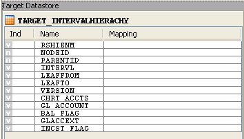
TARGET_INTERVAL_HIERARCHYdatastore from theOracle_Target Model W_SD_DELIVERY_CUBE_SOLDTO -
Drag this datastore into the Target Datastore panel (right area of the Diagram tab). This panel appears now as shown below:
Description of the illustration HierachyInfoobject_html_m1671e86c.png
-
In the Models tree view, select the InfoObject
0GL_ACCOUNTfrom the SAP BW Source model. -
Drag this datastore into the Sources diagram panel (left area of the diagram tab).
-
If a popup window prompting "Do you want to perform Automatic Mapping?" appears, click No.
-
Perform the same operation for the InfoObject hierarchy table
HIER_0GL_ACCOUNTdatastore from the SAP BW Source model. The Sources diagram should look as shown below: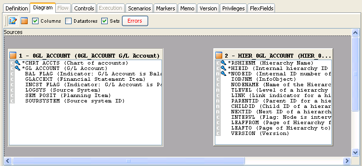
Description of the illustration HierachyInfoobject_html_m1544e8c9.png
Define Joins between Sources (Info Object Main table and InfoObject Hierarchy Table)
The join between InfoObject and InfoObject Hierarchy table may automatically be added by ODI. - There may be situations when more than one join shows up. E.g. when the same InfoObject is referenced more than once in different characteristics. Such unwanted extra joins have to be removed.
Apply source-side Filters on RSHIENM and VERSION:

Description of the illustration HierachyInfoobject_html_m712df372.png

Description of the illustration HierachyInfoobject_html_m78db267b.png
Add joins: all joins must be executed on staging area. Not on source.
The join expression looks like this:
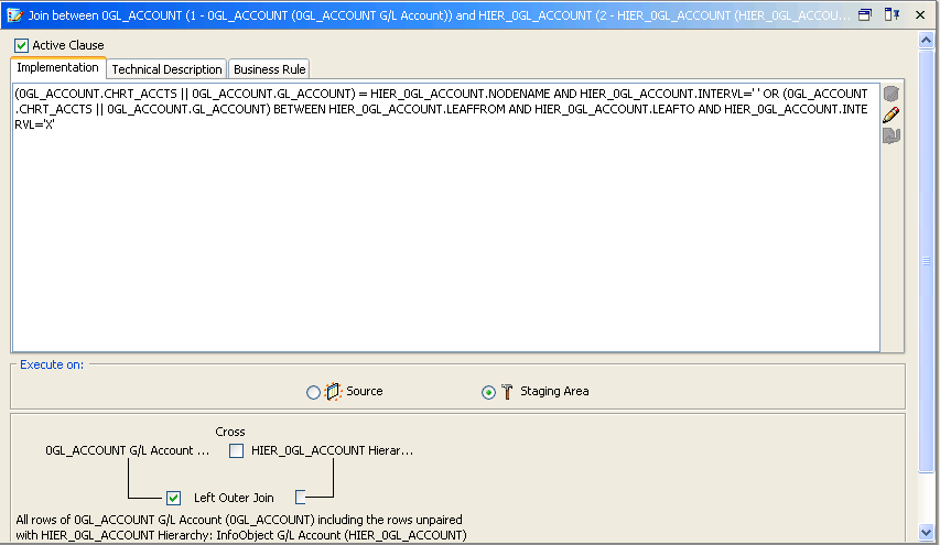
Description of the illustration HierachyInfoobject_html_287a41c0.png
The final join and filter setup should look like this:

Description of the illustration HierachyInfoobject_html_9cc0776.png
Create the Mappings
To create the mappings of the target datastore:
-
Drag the HIER_0GL_ACCOUNT.NODEID column from the HIER_0GL_ACCOUNT Delivery service Source data target into the Implementation field of the Properties panel.
-
Make sure that the Execution On is set to Source. The mapping should look as shown below:
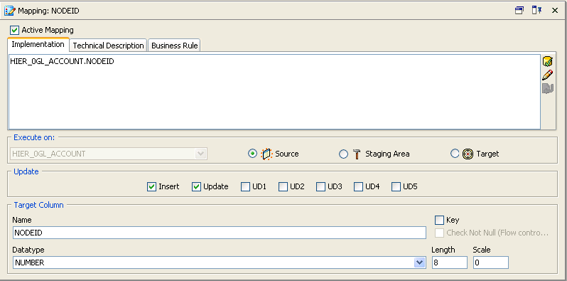
Description of the illustration HierachyInfoobject_html_24993572.png
-
Repeat this operation to perform the following simple mappings:
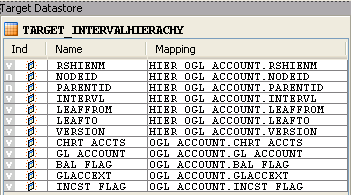
Description of the illustration HierachyInfoobject_html_317ab3ac.png
Define the Interface Flow
To define the interface flow:
-
Select the Flow tab and verify that
LKM SAP BW to Oracle (SQLLDR)orLKM SAP BW to SQLhas been set for every ODI Source Set. The Flow diagram looks as shown below; -
Verify that
LKM SAP BW to Oracle (SQLLDR)orLKM SAP BW to SQLhas been set for every ODI Source Set.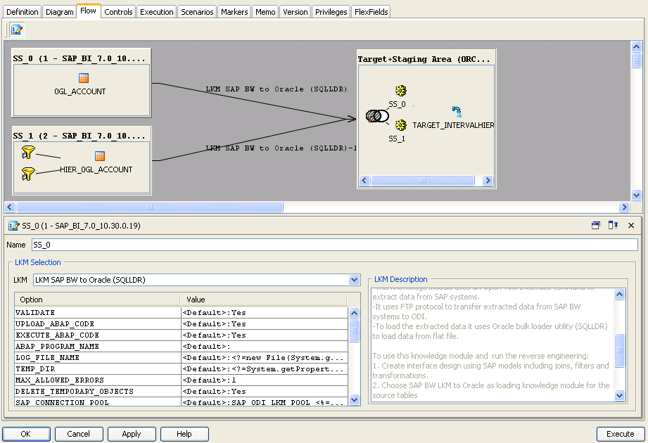
Description of the illustration HierachyInfoobject_html_61501ab6.png
-
Verify that "IKM SQL Control Append" has been set for ODI Target+Staging Area.
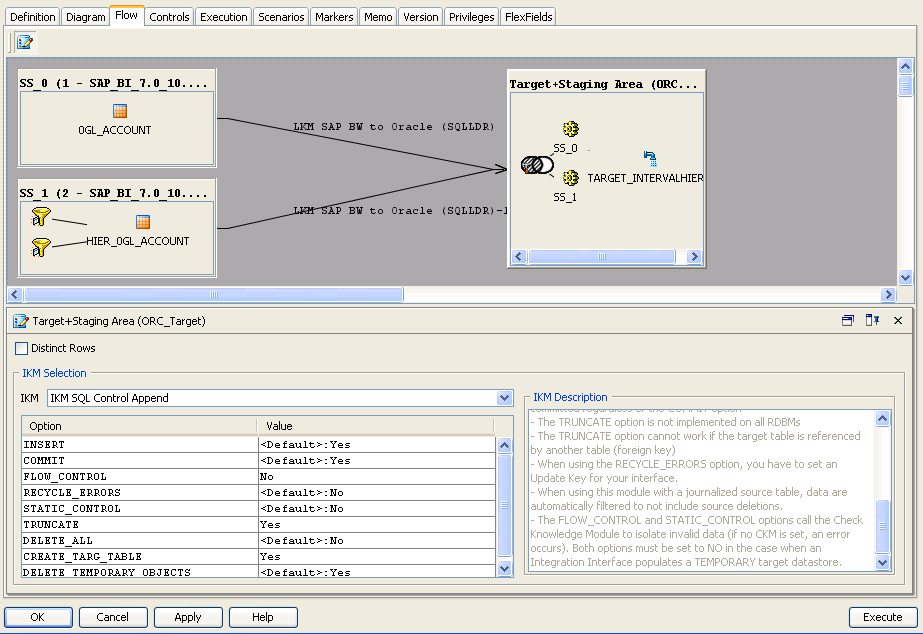
Description of the illustration HierachyInfoobject_html_6da09fb8.png
-
Execute Interface. Verify that data got populated into the target datastore.
ODS/DSO Extraction
This section describes how to create an integration interface in ODI in order to load data from a SAP BW source model representing the ODS/DSO 0BBP_PO data target to the W_PURCH_DS Oracle target model.
Create the Interface
-
Open Designer.
-
In the Projects tree view, expand the
SAP BW DemoProject. -
Expand the
SAP_BW_DataTargetsfolder. -
Select the Interfaces node.
-
Right-click and select Insert Interface.
-
In the Interface Definition tab, enter the interface name:
ODS_SAP_BW_PurchOrdl.W_PURCH_DS. -
Select the Diagram tab.
-
Click OK if the following information window appears.

Description of the illustration image034.jpg
The interface diagram looks as follows:

Description of the illustration image071.jpg
Define the Source and Target Datastores
To define the source and target datastores:
-
In the Models tree view, select the
W_PURCH_DSdatastore from theOracle_TargetModel. -
Drag this datastore into the Target Datastore panel (right area of the Diagram tab). This panel appears now as shown below:

Description of the illustration image073.jpg
-
In the Models tree view, select the
0BBP_PO Purchase Order - Single Documentsdatastore from theSAP BWSource model. -
Drag this datastore into the Sources diagram panel (left area of the diagram tab).
-
If a popup window prompting "Do you want to perform Automatic Mapping?" appears, click No.
-
The Sources diagram should look as shown below:

Description of the illustration image075.jpg
Create the Mappings
To create the mappings of the target datastore:
-
Select the
PO_GUIDEcolumn from the target datastore. -
Drag the
BBP_POGUIDcolumn from the0BBP_PO Purchase Order - Single Documentssource data target into the Implementation field of the Properties panel. -
Make sure that the Execution On is set to Source. The mapping should look as shown below:

Description of the illustration image077.jpg
-
Repeat this operation to perform the following simple mappings:
-
W_PURCH_DS.ORDER_ITEM_GUID = 0BBP_PO.BBP_POITGU -
W_PURCH_DS.ACC_ASS_GUID = 0BBP_PO.BBP_ACGUID -
W_PURCH_DS.GUIDE_CONTRCT = 0BBP_PO.BBP_CTGUID -
W_PURCH_DS.ORDER_QUANT = 0BBP_PO.BBP_ASPQOU -
W_PURCH_DS.NET_PRICE = 0BBP_PO.BBP_NETPRC -
W_PURCH_DS.PRICE_UNIT = 0BBP_PO.BBP_PRCUNT -
W_PURCH_DS.NO_OF_PURCH_ODR = 0BBP_PO.BBP_POCT
-
Define the Interface Flow
To define the interface flow:
-
Select the Flow tab. The Flow diagram looks as shown below;

Description of the illustration image079.jpg
-
Select the source set
SS_0 (SAP_BW)that containsODS/DSO 0BBP_POdata targets. This source set represents the source dataset made up ofSAP BWdata target. -
In the LKM Selection box, select
LKM SAP BW to Oracle (SQLLDR)orLKM SAP BWto SQL. -
Select the Target + Staging Area box. This represents the target Oracle database, which is also used as the staging area for this interface.
-
In the IKM Selection, select
IKM Oracle Incremental Update. -
Set the IKM options as follows:
-
Select No for the FLOW_CONTROL option.
-
Leave other options as it is. The flow should look as shown below:

Description of the illustration image081.jpg
-
-
Click OK to save and close your interface.
Info Cube & Related Info Object Extraction
This section describes how to create an integration interface in ODI in order to load data from a SAP BW source model representing the Info Cube 0FIAP_C20 and Info Object 0CREDITOR data targets join to the W_VENDER_CUBE_OBJ_DS Oracle target model.
Create the Interface
-
Open Designer.
-
In the Projects tree view, expand the
SAP BW DemoProject. -
Expand the
SAP_BW_DataTargetsfolder. -
Select the Interfaces node.
-
Right-click and select Insert Interface.
-
In the Interface Definition tab, enter the interface name:
InfoCube_InfoObject_join.W_VENDER_CUBE_OBJ_DS. -
Select the Diagram tab.
-
Click OK if the following information window appears.

Description of the illustration image034.jpg
The interface diagram looks as follows:

Description of the illustration image082.jpg
Define the Source and Target Datastores
To define the source and target datastores:
-
In the Models tree view, select the
W_VENDER_CUBE_OBJ_DSdatastore from theOracle_TargetModel. -
Drag this datastore into the Target Datastore panel (right area of the Diagram tab). This panel appears now as shown below:

Description of the illustration image084.jpg
-
In the Models tree view, select the Info Cube
0FIAP_C20 Vendor Balancesdatastore from theSAP BWSource model. -
Drag this datastore into the Sources diagram panel (left area of the diagram tab).
-
If a popup window prompting "Do you want to perform Automatic Mapping?" appears, click No.
-
Perform the same operation for the Info Object's main table
0CREDITOR Vendorand text tableTXT_0CREDITOR Texts: Char. Vendordatastore from theSAP BW Sourcemodel.
The Sources diagram should look as shown below:

Description of the illustration image086.jpg
Define Joins between Sources (Info Cube & Object)
To create joins between the source datastores of an interface:
-
In the Sources diagram drag the
IOPK_0FIAP_C202_0CREDITOR_PK_VENDORcolumn from the Info Cube0FIAP_C20 Vendor Balancesdatastore onto theVENDORcolumn in the Info Object's main table0CREDITOR Vendor. This defines the first join on the Vendor Key identifier, as shown below:
Description of the illustration image088.jpg
-
In the Properties panel, you can see the join clause:
0FIAP_C20.IOPK_0FIAP_C202_0CREDITOR_PK_VENDOR=0CREDITOR.VENDOR -
In the Properties panel, select
Ordered joinand make sure that this join is executed on the Source as shown below:
Description of the illustration image090.jpg
-
Make sure that table number of
0FIAP_C20is smaller than that of0CREDITOR. In 1:n relationships the parent data target has to be the first in a join. -
Change join between
0FIAP_C20and0CREDITORto left outer join (All rows from0FIAP_C20and matching ones from0CREDITOR. -
Change join between
0CREDITORandTXT_0CREDITORto left outer join (All rows from0CREDITORand matching ones fromTXT_0CREDITOR.
Create the Mappings
To create the mappings of the target datastore:
-
Select the
COMP_CODEcolumn from the target datastore. -
Drag the
IOPK_0FIAP_C201_0COMP_CODE_PK_COMP_CODEcolumn from the0FIAP_C20 Vendor Balancessource data target into the Implementation field of the Properties panel. -
Make sure that the Execution On is set to Source. The mapping should look as shown below:

Description of the illustration image091.jpg
-
Repeat this operation to perform the following simple mappings:
-
W_VENDER_CUBE_OBJ_DS.VENDOR = 0FIAP_C20.IOPK_0FIAP_C202_0CREDITOR_PK_VENDOR -
W_VENDER_CUBE_OBJ_DS.GL_ACCOUNT = 0FIAP_C20.IOPK_0FIAP_C202_0RC_ACCOUNT_PK_GL_ACCOUNT -
W_VENDER_CUBE_OBJ_DS.SALES_FOR_PERIOD = 0FIAP_C20.KF_0SALES -
W_VENDER_CUBE_OBJ_DS.CUM_BALANCE = 0FIAP_C20.KF_0BALANCE -
W_VENDER_CUBE_OBJ_DS.PLANT = 0CREDITOR.PLANT -
W_VENDER_CUBE_OBJ_DS.MEDIUM_DESC = TXT_0CREDITOR.TXTMD
-
Define the Interface Flow
To define the interface flow:
-
Select the Flow tab. The Flow diagram looks as shown below;

Description of the illustration image093.jpg
-
Select the source set
SS_0 (SAP_BW)that contains both theInfo Cubeand Info Object tables. This source set represents the source dataset made up of two joinedSAP BWdata targets. -
In the LKM Selection box, select
LKM SAP BW to Oracle (SQLLDR)orLKM SAP BWto SQL. -
Select the Target + Staging Area box. This represents the target Oracle database, which is also used as the staging area for this interface.
-
In the IKM Selection, select
IKM Oracle Incremental Update. -
Set the IKM options as follows:
-
Select No for the FLOW_CONTROL option.
-
Leave other options as it is. The flow should look as shown below:

Description of the illustration image095.jpg
-
-
Click OK to save and close your interface.
Info Cube Extraction with Navigational Attributes
This section describes how to create an integration interface in ODI in order to load data from a SAP InfoCube and its navigation attributes. The data is extracted from Info Cube 0SD_C04 and InfoObject 0SOLD_TO.
Create the Interface
-
Open Designer.
-
In the Projects tree view, expand the
SAP BW DemoProject. -
Expand the
SAP_BW_DataTargetsfolder. -
Select the Interfaces node.
-
Right-click and select Insert Interface.
-
In the Interface Definition tab, enter the interface name:
InfoCube_InfoObject_Nav_join.0SD_C04. -
Select the Diagram tab.
Define the Source and Target Datastores
To define the source and target datastores:
-
In the Models tree view, select the
0SD_C04datastore from the Oracle Target ModelW_SD_DELIVERY_CUBE_SOLDTO. -
Drag this datastore into the Target Datastore panel (right area of the Diagram tab).The following panel appears:

Description of the illustration image097.jpg
-
In the Models tree view, select the Info Cube
0SD_C04 Delivery service datastorefrom theSAP BWSource model. -
Drag this datastore into the Sources diagram panel (left area of the diagram tab).
-
If a popup window prompting "Do you want to perform Automatic Mapping?" appears, click No.
-
Perform the same operation for the Info Object main table
0SOLD_TO Customer datastorefrom theSAP BWSource model.The Sources diagram should appear as follows:

Description of the illustration image099.jpg
Define Joins Between Sources (Info Cube & Info Object)
The join between InfoCube and InfoObject will automatically be added by ODI. - There may be situations when more than one join shows up. E.g. when the same InfoObject is referenced more than once in different characteristics. Such unwanted extra joins have to be removed.
The final join setup with its join expression should look like this:

Description of the illustration image101.jpg
All InfoObject joins for retrieving navigation attributes must be executed on *staging* area. Not on source:

Description of the illustration image103.jpg
Create the Mappings
To create the mappings of the target datastore:
-
Drag the
0SD_C04.IOPK_0SD_C041_0SOLD_TO_PK_CUSTOMERcolumn from the0SD_C041 Delivery serviceSource data target into the Implementation field of the Properties panel. -
Make sure that the Execution On is set to Source. The mapping should look as shown below:

Description of the illustration image105.jpg
-
Repeat this operation to perform the following simple mappings:

Description of the illustration image107.jpg
Define the Interface Flow
To define the interface flow:
-
Select the Flow tab and verify that "LKM SAP BW to Oracle (SQLLDR)" has been set for every ODI Source Set. The Flow diagramappears as follows:

Description of the illustration image109.jpg
-
Verify that
LKM SAP BW to Oracle (SQLLDR)orLKM SAP BWto SQL has been set for every ODI Source Set.Note:
This interface will generate several SAP ABAP extraction programs. One for retrieving any display attributes and key figures from the InfoCube and one for each InfoObject containing navigation attributes.
-
Verify that "IKM SQL Control Append" has been set for ODI Target+Staging Area.

Description of the illustration image111.jpg
-
Execute Interface. Verify that Info Cube and Navigational attributes got populated into the target datastore.
Open Hub Extraction
This section describes how to create an integration interface in ODI in order to load data from a SAP BW source model representing the Open Hub destination ZOHD_SALE (/BIC/OHZOHD_SALE) to the W_OPENHUB_SALES_DS Oracle target model.
Create the Interface
-
Open Designer.
-
In the Projects tree view, expand the
SAP BW DemoProject. -
Expand the
SAP_BW_DataTargetsfolder. -
Select the Interfaces node.
-
Right-click and select Insert Interface.
-
In the Interface Definition tab, enter the interface name:
OpenHub_Sales.W_OPENHUB_SALES_DS. -
Select the Diagram tab.
-
Click OK if the following information window appears.

Description of the illustration image034.jpg
The interface diagram looks as follows:

Description of the illustration image112.jpg
Define the Source and Target Datastores
To define the source and target datastores:
-
In the Models tree view, select the
W_OPENHUB_SALES_DSdatastore from theOracle_TargetModel. -
Drag this datastore into the Target Datastore panel (right area of the Diagram tab). This panel appears now as shown below:

Description of the illustration image114.jpg
-
In the Models tree view, select the
ZOHD_SALEdatastore from theSAP BW Sourcemodel. -
Drag this datastore into the
Sourcesdiagram panel (left area of the diagram tab). -
If a popup window prompting "Do you want to perform Automatic Mapping?" appears, click No.
-
The Sources diagram should look as shown below:

Description of the illustration image116.jpg
Create the Mappings
To create the mappings of the target datastore:
-
Select the
OHREQUIDcolumn from the target datastore. -
Drag the
OHREQUIDcolumn from theZOHD_SALEsource data target into the Implementation field of the Properties panel. -
Make sure that the Execution On is set to Source. The mapping should look as shown below:

Description of the illustration image118.jpg
-
Repeat this operation to perform the following simple mappings:
-
W_OPENHUB_SALES_DS.DATA_PACKAGE = ZOHD_SALE.DATAPAKID -
W_OPENHUB_SALES_DS.DATA_RECORD = ZOHD_SALE.RECORD -
W_OPENHUB_SALES_DS.CUSTOMER = ZOHD_SALE.D_CUSTOMER -
W_OPENHUB_SALES_DS.MATERIAL = ZOHD_SALE.D_MATERIAL -
W_OPENHUB_SALES_DS.MATERIAL_PRICE = ZOHD_SALE.PRICE_MAT -
W_OPENHUB_SALES_DS.CURRENCY = ZOHD_SALE.CURRENCY -
W_OPENHUB_SALES_DS.QUANTITY = ZOHD_SALE./BIC/ZQTY -
W_OPENHUB_SALES_DS.TOTAL_REVENUE = ZOHD_SALE./BIC/ZREV
-
Define the Interface Flow
To define the interface flow:
-
Select the Flow tab. The Flow diagram looks as shown below;

Description of the illustration image120.jpg
-
Select the source set
SS_0 (SAP_BW)that contains Open Hub Destination TableZOHD_SALE. This source set represents the source dataset made up ofSAP BWOpen Hub table. -
In the LKM Selection box, select
LKM SAP BW to Oracle (SQLLDR)orLKM SAP BWto SQL. -
Select the Target + Staging Area box. This represents the target Oracle database, which is also used as the staging area for this interface.
-
In the IKM Selection, select
IKM Oracle Incremental Update. -
Set the IKM options as follows:
-
Select No for the FLOW_CONTROL option.
-
Leave other options as it is. The flow should look as shown below:

Description of the illustration image122.jpg
-
-
Click OK to save and close your interface.
Running the Integration Interface
This section contains the following topics:
Running the Interface
To run the integration interface:
-
In the Projects tree view, expand the
SAP DemoProject -
Expand the
SAP_BW_DataTargetsfolder. -
Expand the Interfaces node.
-
Select the
InfoCube_SAP_BW_VendorBal.W_VENDR_BAL_DSinterface. -
Right-click and select Execute.
-
In the Execution window that appears, click OK.
-
Click OK in the Session Started window.
What happens when you run the interface?
First, Oracle Data Integrator creates an ABAP program that does the following:
-
It performs the extraction of the data on the SAP BW system. In this example, the extraction will be done on Info Cube source data targets and then returns the resultset in an extraction file.
-
It uploads the extraction file into a FTP data server. This FTP host is specified via the File Logical Schema called File Server for SAP ABAP. This Logical Schema is mapped to a Physical Schema and therefore a data server in the given context. This data server contains the connection information for the FTP host.
Then, the ABAP code is uploaded using the OdiSapAbapExecute tool. The ABAP program is pushed into the SAP Function group given in the SAP_FUNCTION_GROUP_NAME LKM option. This phase can be suppressed by setting the UPLOAD_ABAP_CODE LKM option to No.
The ABAP code is executed also by the OdiSapAbapExecute tool. At the end of the ABAP code execution, the extraction file is available in the FTP host.
The Oracle Data Integrator agent is able to download this extraction file from the FTP host, or directly access it, depending on the FTP_TRANSFER_METHOD specified in the IKM option.
Finally, when the agent accesses the extraction file, it uses SQL*Loader or a JDBC Connection to load this file into the Oracle/non-Oracle staging area. The rest of the integration process takes place within the Oracle/non-Oracle engine.
Review the Interface Execution
To review the interface execution:
-
Connect to Operator.
-
In the Operator, select the Session List tree view.
-
Expand the All Executions node in this tree view.
-
The latest session is the first entry of this list and appears as shown below.

Description of the illustration image124.jpg
-
Double click the
InfoCube_SAP_BW_VendorBal.W_VENDR_BAL_DSnode to see the session details and the number of lines processed.
Review the Resulting Data
To review the resulting data:
-
In the Designer, in the Models tree view, expand the
Oracle TargetModel. -
Select the
W_VENDR_BAL_DSdatastore, right-click and select Data to view the data integrated into the target Oracle table. -
Repeat the same steps for remaining interfaces:
-
InfoObject_SAP_BW_VendorAcc.W_ACCNT_VENDR_DS -
ODS_SAP_BW_PurchOrdl.W_PURCH_DS -
InfoCube_InfoObject_join.W_VENDER_CUBE_OBJ_DS -
OpenHub_Sales.W_OPENHUB_SALES_DS
-