6 Simulating Process Behavior
This provide information on using Oracle Business Process Composer to run simulations to improve the performance of your business processes. It describes how to create simulation models and simulation definitions. It also describes how to run a simulation and analyze the results.
This chapter contains the following sections:
6.1 Introduction to Simulations
Oracle BPM provides functionality for simulating the behavior and performance of BPMN processes. Using Business Process Composer, process designers can run simulations during the design phase.
After creating and configuring a simulation, you run it in Business Process Composer to determine the efficiency of process using the resources allocations you have defined. Using simulations, you can:
-
Define multiple simulation models for a given process so that different conditions can be analyzed
-
Run multi-process simulations to learn how working in different business processes can affect shared resources such as human participants
Note:
In Business Process Composer you can only run simulations based on test data you define using Business Process Composer. You can run simulations on real-world data using Oracle BPM Studio.
6.1.1 Simulation Models and Simulation Definitions
Before running a simulation, you must define the simulated behavior of the project as and the processes you want to include in the simulation. To define a simulation you must create and configure the following in your BPM Project:
-
Simulation definition
Simulation definitions define the processes and resources for a specific scenario. In a simulation definition you specify the processes included in the simulation by selecting the simulation models associated to those processes. A process can have multiple simulation models defined for it. If a process has multiple simulations models defined, then you must select one of those models to use in the simulation definition.
Within a BPM project you can define multiple simulation definitions, each with its own parameter definitions and simulation models. This enables you to compare multiple scenarios.
-
Simulation model
Simulation models define the simulated behavior of an individual process model. You can have multiple simulation models for each business process, enabling you to simulate different scenarios.
Simulations do not call each individual task within a process. For example, they do not run the service associated to a service task, variables are not assigned values, and external resources are not updated.
6.1.2 Simulation Parameters
In addition to the general parameters defined for a simulation definition and a simulation model, you can also define simulation parameters for the start events and activities within a BPMN process.
6.1.2.1 General Simulation Definition Parameters
The following parameters define the general behavior of a simulation definition.
-
Simulation definition: defines the name of the simulation definition.
-
Duration: defines the period the simulation runs. This interval is specified in months, days, hours, minutes, and seconds.
-
Start time: defines the start time for the simulation. This time is used only for logging. It is not used for scheduling purposes.
-
Let in-flight instances finish before simulation ends: If selected, simulation ends only when the specified number of instances completes. If deselected, simulation stops after the simulation duration is completed. At that point, all incomplete instances are shown in either “in-process” or “queue” status.
You must define these parameters when creating a simulation definition. However, you can redefine them later if necessary.
6.1.2.2 Simulation Model Parameters
The following parameters define the general behavior of a simulation model:
-
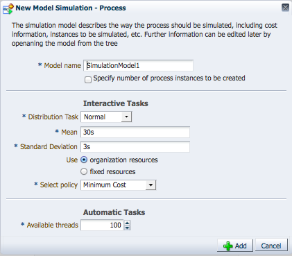
Model name: defines the name of the simulation model.
-
Specify number of process instances to be created: specifies the number of simulated instances are created during simulation.
-
Interactive tasks: defines the distribution type used for interactive tasks. The available distribution types are:
-
Constant
-
Uniform
-
Exponential
-
Normal
These are identical to the distribution methods defined for specific activities within a process. When you change distribution type or other parameters for a specific activity within a process, these values override the general values defined in the simulation model. See Section 6.1.2.5, "Activity Parameters" for more information.
-
-
Automatic tasks: defines the number of simulated threads available when performing an automatic task. This parameter is identical to the Threads parameter you can define for individual activities within your process. See Section 6.1.2.5, "Activity Parameters" for more information.
6.1.2.3 Resource Parameters
Resources define the simulated resources within your organization. Resources are defined in a simulation definition and can be shared between each of the process models included. These resources can be associated with a specific role within your project. You can use these parameters together to create a resource profile that determines the expense, time, and efficiency of a person or group.
The following resource parameters are supported:
-
Name: defines the name of the resource.
-
Cost per hour: specifies the cost of the resource per hour when performing an activity.
-
Efficiency: specifies how efficient the resource is when performing an activity. This parameter is used when selecting the Maximum efficiency policy when defining how organizational resources are allocated. See Section 6.1.2.5, "Activity Parameters" for more information.
-
Capacity: specifies how many activities can be performed at one time.
-
Availability: specifies the percentage of time this resource is available.
-
Roles: specifies the roles associated to this resource.
6.1.2.4 Start Event Parameters
To simulate the behavior and performance of start events, Oracle BPM uses a statistical model that simulates the probability of a certain behavior. You must select the statistical distribution that Oracle BPM uses.
The following distribution types are available:
-
Constant: triggers the start event at a specific interval. For example, if you specify a period of 1 minute and 15 seconds, the event is triggered every 1 minute and 15 seconds. Each time the event is triggered, a new instance of the process is created.
-
Uniform: repeats the start event at intervals within a specific margin specified by the mean and delta parameters. For example, if you define the mean as 30 seconds and the delta as 3 seconds, the start even creates a new instance in intervals between 27 and 33 seconds, with an equal probability.
-
Exponential: triggers the start event a specified number of times within a certain interval. For example, if you define the frequency as 10 and the interval as 1 hour, the event is triggered 10 times per hour. The distribution of events is based on exponential distribution.
-
Normal: triggers the start event base on normal, or Gaussian, distribution. This is a continuous probability distribution that repeats based on a bell curve. For example, if you define a mean of 10 minutes and a standard deviation of 2 minutes, the event will repeat according to the probabilities shown in Figure 6-1.
Figure 6-1 Simulation - Normal Distribution in a Start Event
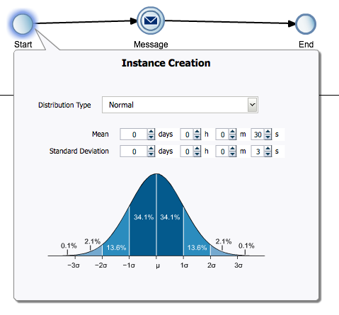
Description of "Figure 6-1 Simulation - Normal Distribution in a Start Event"
In this example, the event has a 62.8 percent probability of repeating in an interval between 8 and 12 minutes.
-
Real: triggers the start event based on user-specified intervals: hourly, daily, weekly, or monthly. You can define the mean and standard deviation for each interval. Using these parameters, the start event creates new process instances using normal distribution.
For example, you can specify a daily distribution with a mean of 5 minutes and a standard deviation of 1 minute for weekdays and a mean of 1 hour and a standard deviation of 10 minutes for weekends.
6.1.2.5 Activity Parameters
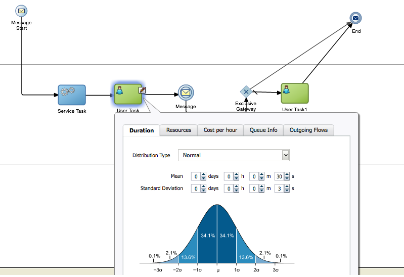
In addition to start events, you can define parameters that determine the simulated behavior or interactive and automatic activities within a process. You define these parameters the tabbed panes of the simulation editor. Figure 6-2 shows an example of the tabbed panes of an interactive activity.
Figure 6-2 Simulation Parameters for an Interactive Activity
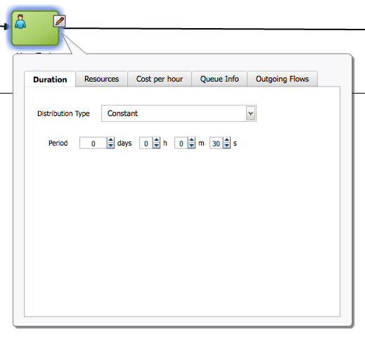
Description of "Figure 6-2 Simulation Parameters for an Interactive Activity"
The simulation parameters for activities are:
-
Duration: defines the statistical model used to determine the amount of time required to perform an activity. The statistical models used are similar to those defined for start events except, instead of defining how often an event is triggered, they define how long it takes to perform the work of a specific activity.
See Section 6.1.2.4, "Start Event Parameters" for a description of each distribution type.
-
Resources (interactive activities only): defines how many interactive activities can be performed simultaneously. You can define how simulated resources are allocated to this activity.
-
Organizational resources: are resources shared between all the processes within a simulation definition. You must specify the policy that determines how the simulated participants are selected to perform the activity.
-
Minimum cost: selects less costly resources first.
-
Maximum efficiency: selects the most efficient resources first.
-
Random: randomly selects between Minimum cost and Maximum efficiency.
See Section 6.1.2.3, "Resource Parameters" for information on defining organization resources within a simulation definition.
-
-
Fixed resources: explicitly defines the number of resources available to perform the interactive activity.
-
-
Threads (available only for automatic activities): defines the number of simulated threads that are used to perform an automatic activity.
-
Cost per hour: defines the cost required to perform the activity. Use this parameter to create cost-base reports.
-
Activity Cost Type: can be defined as a base cost or as a base cost plus the cost of resources assigned to perform the activity.
-
Activity Fixed Base Cost: defines the value (specified as a decimal number) of the fixed base cost.
See Section 6.1.2.3, "Resource Parameters" for information on defining organization resources within a simulation definition.
-
-
Queue info: specifies the maximum size of the queue for this activity. This is the number of instances that are currently waiting at this activity. When this number reaches the maximum size, the simulation issues a warning.
-
Outgoing flows: specifies the probability (defined as a decimal number) of a process instance continuing along each of the outgoing sequence flow. If only one outgoing sequence flow is defined, the probability is specified as 1 and cannot be changed.
6.2 Creating and Running a Simulation
To run a simulation, you must first define a simulation model for your project and at least one simulation definition for each of the processes you want to include in your simulation. You can create multiple simulation definitions to test and compare the performance of your processes.
To create and run a simulation:
-
Create the BPMN processes you want to include in your simulation.
See Section 5.3, "Working with Business Processes" for information about creating and working with business processes.
-
Create a simulation definition and simulation models.
The initial simulation model for a process can only be created in the simulation definition editor. After you have created at least one simulation model for a process, you can create additional simulation models for a process.
See Section 6.3.1, "How to Create a Simulation Definition" for information about running the simulation wizard to create simulation definitions and simulation models.
-
Configure parameters to define the simulated behavior of your processes.
See Section 6.1.2, "Simulation Parameters" for information about the different parameters you can define for a simulation definition and simulation model. See Section 6.4.2, "How to Edit a Simulation Model"for information about how to configure parameters for the flow objects within your process.
-
Run the simulation.
After creating and configuring a simulation definition and simulation model, you can run your simulation.
See Section 6.5, "Running Simulations" for more information.
-
Analyze the results of the simulation.
After running a simulation you can analyze the results of the simulation and make adjustments to the parameters to determine how to improve the performance of your process. See Section 6.6, "Analyzing the Results of a Simulation" for more information.
6.3 Working with Simulation Definitions
Simulation definitions define the simulated behavior of your BPM project as a whole. Within a simulation definition, you can define general parameters, including the organizational resources, and select which simulation models to include in a simulation. You can define multiple simulation definitions to test different combinations of parameters and processes.
After creating a simulation definition, you can edit its resources, add simulation models, etc. as described in the following sections.
6.3.1 How to Create a Simulation Definition
In a simulation definition, you can changes the values of different parameters to see how they influence the performance a project. The parameters you can define include:
-
The start time and duration of the simulation
-
Which process simulation models you want to include in the project simulation
-
Participant resources you want to include in the simulation
Business Process Composer provides a wizard that walks you through the process of creating and configuring a new simulation definition, creating and configuring new simulation models, and configuring organizational resources.
To create and configure a simulation definition:
-
In the Project Welcome page toolbar, click Simulate as shown in Figure 6-3.
Figure 6-3 The Simulate Button in the Project Welcome Page

Description of "Figure 6-3 The Simulate Button in the Project Welcome Page"
The Simulation editor appears.
-
Click the Add (+) icon as shown in Figure 6-4.
-
Enter a name for the simulations and values for the duration and start time of the simulation definition.
You must define these parameters when creating a simulation definition. However, you can redefine them later if necessary.
See Section 6.1.2.1, "General Simulation Definition Parameters" for more information about each of these parameters.
-
Click Next.
-
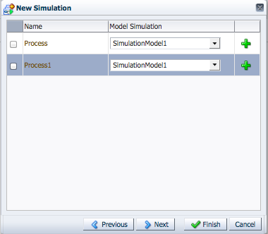
Create a new simulation model for each process you want to include in the simulation definition.
Simulation models can be shared across simulation definitions. However, the first time you create a simulation definition, you must create at least one simulation model for each process if you have not created one previously.
-
Click the Add (+) icon to create a new simulation model as shown in Figure 6-5.
A simulation model defines the simulated behavior of a process. You can define multiple simulation models for a process, however only one simulation model is used for each process within a simulation definition.
-
Provide information for each of the fields as shown in Figure 6-6.
Figure 6-6 The New Simulation Model Editor
Description of "Figure 6-6 The New Simulation Model Editor"
See Section 6.1.2.2, "Simulation Model Parameters" for more information about these parameters.
-
Click Add.
Create additional simulation models as necessary. You should create at least one simulation model for each process in your project even if you do not include it in the simulation definition. This enables you to create additional simulation models later and add them to other simulation definition.
-
-
Select the check box next to each process whose simulation model you want to include in the simulation definition as shown in Figure 6-5.
If you have not created a simulation model for a process, you cannot select the process.
-
Click Next.
-
Optionally, click the Add resource icon to add resources to the simulation definition.
See Section 6.1.2.3, "Resource Parameters" for information on the resource parameters you can define.
-
Click Finish.
6.3.2 What Happens When You Create a Simulation Definition
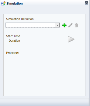
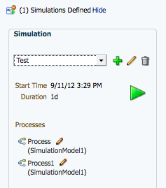
After creating a new simulation definition and simulation models the simulation panel appears as shown in Figure 6-7.
Figure 6-7 The Simulation Panel After Creating a Simulation Definition
Description of "Figure 6-7 The Simulation Panel After Creating a Simulation Definition"
This panel displays a drop down list containing all the simulation definitions defined in your project. It also displays all the simulation models included in the currently selected simulation definition. If you select a different simulation definition from the drop down list, the simulation panel displays the simulation models defined for that simulation definition.
From this panel you can perform the following tasks:
-
Edit a simulation definition. See Section 6.3.3, "How to Edit a Simulation Definition" for more information.
-
Run a simulation. See Section 6.5.1, "How to Run a Simulation" for more information.
-
Edit a simulation model. See Section 6.4.2, "How to Edit a Simulation Model" for more information.
6.3.3 How to Edit a Simulation Definition
After creating a simulation definition, you can edit it from the simulation panel.
To edit a simulation definition:
-
From the Project Welcome page toolbar, click Simulate as shown in Figure 6-3.
After clicking Simulate, the simulation panel appear as shown in Figure 6-7.
-
From the drop down list, select the simulation definition you want to edit, then click the Edit icon.
The simulation definition editor appear in a tabbed pane as shown in Figure 6-8.
Figure 6-8 The Simulation Definition Editor

Description of "Figure 6-8 The Simulation Definition Editor"
From this editor, you can add or remove simulation models from a simulation definition, add resources, and run simulations.
-
Edit the Start Time, Duration, and End Time as necessary. See Section 6.1.2.1, "General Simulation Definition Parameters" for more information about these parameters.
-
To add resources to a simulation definition, click the Add Resource icon, then edit the fields of the Resources table as necessary. See Section 6.1.2.3, "Resource Parameters" for more information about the parameters you can define for a resource.
6.3.4 How to Add a Simulation Model to a Simulation Definition
Before creating a new simulation model, you need to create at least one simulation definition. See Section 6.3.1, "How to Create a Simulation Definition" for more information.
To add a simulation model to a simulation definition:
-
From the Project Welcome page toolbar, click Simulate as shown in Figure 6-3.
-
From the drop down list, select the simulation definition where you want to add a simulation model.
New simulation models are created from the simulation definition editor. However after creating a simulation model for a process, it can be shared with multiple simulation definitions.
-
Click the Edit icon.
-
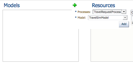
Click the Add Model Simulation icon in the Model pane.
-
Select a process from the drop down list, then select a simulation model as shown in Figure 6-9.
Figure 6-9 Adding a simulation model to a simulation definition
Description of "Figure 6-9 Adding a simulation model to a simulation definition"
-
Click Add.
-
The new simulation model appears in the list.
6.4 Working with Simulation Models
Simulation models enable you to simulate the behavior of an individual process. They enable you to define how a process behaves as part of a simulation definition.
You can define multiple simulation models for each process, creating different simulations based on different combinations of resource allocation and activity behavior.
6.4.1 How to Create a New Simulation Model
You can create multiple simulation models for a process. Different models can be included in different simulation definitions to determine performance based on different parameter settings.
Note:
You cannot directly create a the first simulation model for a process. The first simulation model for a process must be created using the simulation definition wizard. After creating the initial simulation model, you can create additional models using the following procedures.
See Section 6.3.1, "How to Create a Simulation Definition" for information about creating a simulation model when creating a simulation definition.
To create a new simulation model for a process
-
In the Project Welcome page toolbar, click Simulate as shown in Figure 6-3.
-
Select a simulation definition that contains the process where you want to create a new simulation definition.
-
Click the edit icon next to the simulation model.
The process opens in the simulation canvas. This canvas is similar to the process editor canvas. You can toggle back and forth between the process designer and simulation canvases using the drop down list in the process editor toolbar
-
In the process editor toolbar, click the Add icon as shown in Figure 6-10.
Figure 6-10 The simulation editor toolbar

Description of "Figure 6-10 The simulation editor toolbar"
-
Enter a name, then click Create.
The new simulation model is created. You can use this model when creating a new situation definition or editing an existing one. See Section 6.3.4, "How to Add a Simulation Model to a Simulation Definition" for more information.
6.4.2 How to Edit a Simulation Model
-
From the Project Welcome page toolbar click Simulate.
-
From the drop down list, select the name of the simulation definition containing the simulation model you want to edit.
-
Click the Edit icon next to the simulation model you want to edit.
The process displays in the simulation canvas. This canvas is similar to the process editor canvas. You can toggle back and forth between the process designer and simulation canvases using the drop down list in the process editor toolbar as shown in Figure 6-10.
Note:
This drop down list only appears after you have defined at least one simulation model for a process.
-
Hover the mouse over the flow object whose simulation information you want to configure, then click the Edit icon of the flow object where you want to define resources.
The simulation definition pane appears as shown in Figure 6-11.
Figure 6-11 The Simulation Model Editor Showing the Resource Definition Panel
Description of "Figure 6-11 The Simulation Model Editor Showing the Resource Definition Panel"
-
Edit the simulation parameters for the flow object by clicking the tab and editing the appropriate parameters. See Section 6.1.2.4, "Start Event Parameters" and Section 6.1.2.5, "Activity Parameters" for information on the parameters you can configure for specific flow objects.
-
After editing the parameters, click outside the popup window to save your changes.
6.5 Running Simulations
After defining a simulation model and simulation definitions, you can run the simulation to view the performance of your BPM project.
6.5.1 How to Run a Simulation
To run a simulation, you must have created at least one simulation definitions and simulation models for each of the processes you want to test.
-
From the Project Welcome page toolbar, click Simulate.
-
Click the Run icon.
6.6 Analyzing the Results of a Simulation
You can display simulation results either as a chart or as a log file by clicking either the Chart tab or the Log tab in the Simulations window.
The Log tab displays a log that tracks the movements of all the instances in the simulated process. Each line in the log contains the following information:
-
Date and Time
-
Process
-
Instance
-
Instance path
6.6.1 How to Analyze the Results of a Simulation Using a Chart
The Chart tab enables you to select a type of chart to display the result of the simulation. You can configure this chart to display the resources to monitor. You can also select the units the chart uses to measure the resources use.
In the Chart tab you can configure how to display the chart with the results of the simulation by configuring the following:
-
Type of chart
-
Activities or resources to monitor
-
Indicators
To analyze the results of the simulation using a chart:
-
From the list below the Chart tab, select the type of chart to display.
They available types are:
-
Column
-
Bar
-
Bar 3D
-
Column 3D
-
Table
-
-
Click the Configure icon located on the right hand side of the Charts tab.
A Configuration dialog box appears.
-
Select a resource or an activity to monitor.
-
Select the axis where to display the activities or resources.
-
From the list below the Show list, select the activities or resources to monitor in the simulation.
-
From the Indicators list, select the type of indicators to monitor.
The available types of indicators are:
-
Cost
-
Time
-
Units
-
-
From the list below the indicators list, select the indicators to monitor.
The chart displays the variables and indicators you selected.
-
Click Close.
-
Optionally, click the drill up and drill down icons located next to the Types list to increase or reduce the level of detail in the chart.
