| Oracle® Fusion Middleware Modeling and Implementation Guide for Oracle Business Process Management 11g Release 1 (11.1.1.6.3) Part Number E15176-11 |
|
|
PDF · Mobi · ePub |
| Oracle® Fusion Middleware Modeling and Implementation Guide for Oracle Business Process Management 11g Release 1 (11.1.1.6.3) Part Number E15176-11 |
|
|
PDF · Mobi · ePub |
This chapter describes how to use create and model business processes using Business Process Management Notation and Modeling (BPMN) within the Oracle Business Process Management Suite.
This chapter provides specific information on about Oracle's implementation of BPMN 2.0. See Chapter 2, "Overview of Business Process Design" for a general introduction to BPMN using the Sales Quote example project. For general information about BPMN, including the formal specification, see http://www.bpmn.org.
This chapter is organized around different types of tasks your business process must perform. It includes the following sections:
Section 6.2, "Defining the Start and End Point of a Process"
Section 6.4, "Communicating With Other Processes and Services"
Section 6.5, "Adding Business Logic Using Oracle Business Rules"
Section 6.6, "Controlling Process Flow Using Sequence Flows"
Section 6.8, "Controlling Process Flow Using Intermediate Events"
Section 6.10, "Changing the Value of Data Objects in Your Process"
Section 6.11, "Measuring Process Performance Using Measurement Marks"
Section 6.12, "Using Guided Business Processes to Set Project Milestones"
This section shows you how to organize your process using swimlanes. It also describes how to use roles to determine which members of your business organization are responsible for performing the work of your process-based application.
A key to designing a business process is determining the people/roles required to complete each of the tasks that require user interaction. Within your process, roles are used to model who is responsible for performing the work performed within your business processes. Roles allow you to define functional categories that represent job functions or responsibilities within your organization.
The roles defined in you process are also referred to as logical roles. When your Oracle BPM project is deployed to the run time environment, these roles are mapped to LDAP roles that correspond to the users in your real-world organization.
Roles are assigned to the horizontal swimlanes that display the roles responsible for completing activities and tasks within your process. Business Process Composer enables you to create and edit the required roles within your process and assign them to swimlanes.
Using Oracle BPM Studio, you can also map roles to specific users using LDAP. Oracle BPM Studio also enables you to create more robust organizational models using organizational units, calendars, and holidays.
Process analysts are generally responsible for determining what roles are required when designing a business process.
The Sales Quote example project defines the following roles:
Sales Rep: Sales representatives are responsible for creating and updating a sales quote until is approved by the other roles defined in the project.
Approvers: Represent users who are responsible for approving the combination of products and pricing structure defined by the sales quote.
Business Practices: Represent users who are responsible for viewing and approving the sales quote. Additionally, they have the authority to add additional approvers during the review of the sales quote.
Contracts: Represent users who are responsible for approval of the terms specified in the sales quote and also for creating the formal legal documents that can be forwarded to the customer.
See Chapter 2, "Introduction to the Sales Quote Example Project" for more information on the Sales Quote example project.
Swimlanes are the horizontal lines that run across the process editor. All flow objects must be placed within a swimlane.
Swimlanes can also be used to group flow objects based on the roles defined within your process. Swimlanes that contain user tasks must have roles assigned to them. Swimlanes visually display the role responsible for performing each flow object within your process. Additionally, you can have multiple swimlanes that are assigned to the same role.
Swimlanes can make your process more readable when you must use the same role in different parts of the same process.
When you create a new process, Oracle BPM Studio and Business Process Composer create a default swimlane. You can add additional swimlanes to your process as necessary. When adding interactive and manual activities to a process, you must assign a role to the swimlane.
Note:
You cannot remove the role for a swimlane that contains a start or end event.
Figure 6-1 shows a simple process split across multiple swimlanes. In this example, the SalesRep role is assigned to the first swimlane. The role is indicated by the swimlane label placed at the front end of the lane. Because the Enter Quote user task appears inside the SalesRep swimlane, process participants assigned to the SalesRep role are responsible for performing this task.
Figure 6-1 A Simple Business Process Split Across Two Swimlanes
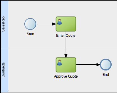
Swimlanes are contained in a pool in the process editor. The name of the process is the label of the pool, which appears immediately before the swimlane labels at the front end of the pool. As you add swimlanes to the process, the pool outline in the process editor will expand to accommodate all swimlanes.
In a real-world business process, the combination of swimlanes and flow objects within them can be complex. The Sales Quote example project shown in Figure 2-1 is an example of a more complex process using multiple swimlanes.
You can add new swimlanes and then add your flow objects or you can add a new flow object and create a new swimlane at the same time.
For each swimlane, you can add a background color to the lane and insert an icon into the swimlane label.
To add a new swimlane and role from a context menu:
Open the process where you want to add a swimlane.
On the process canvas, below an existing swimlane, right-click and choose Add Role.
Select a role from the Name dropdown list or click New to create a new role.
Click OK. (If you created a new role, click OK twice.)
The new swimlane is created. The process pool is expanded to contain the newly added swimlane.
To add a new swimlane and role as you add a new flow object:
Open the process where you want to add a new flow object in a new swimlane.
From the Component Palette, select a user or manual task flow object, then drag and drop it on the process canvas below an existing swimlane.
You must select either a user or manual task. Only these tasks can be used to create a new swimlane.
Edit the flow object properties as necessary in the dialog that opens, then click OK.
Select a role from the Name dropdown list or click New to create a new role.
Click OK. (If you created a new role, click OK twice.)
The new swimlane is created. The process pool is expanded to contain the newly added swimlane.
To add a background color to a swimlane:
Open the process where you want to add a color to a swimlane.
Right-click the swimlane label and choose Properties.
Click the rectangular swatch next to Translucent background.
Choose a color from the palette.
Click OK twice.
Note:
To remove a background color, click the Clear icon next to the swatch.
To insert an icon into a swimlane label:
Open the process where you want to add an icon to a swimlane label.
Right-click the swimlane label and choose Properties.
Click the Browse tool to open the Image Browser.
Select an image.
Click OK twice.
Note:
To remove an icon from a swimlane label, click the Clear icon next to the Browse tool.
Oracle BPM Studio enables you to integrate roles within a complex organization models based on organizational units, calendars and holidays.
When editing a project or creating a project based on a project template in Business Process Composer, you can access the roles defined within the project. However, you cannot view or edit the organizational information defined within the project.
Additionally, you can create new roles using Business Process Composer. These roles are incorporated as part of the overall organization information of the project.
The update task is used to perform operation on one or more Human Tasks. For example, you can use the update task perform actions like reassigning a task to another user.
Figure 6-2 shows the default notation for the update task.
See Section 14.3, "Updating User Tasks Using Update Tasks" for more information on implementing the update task.
This section describes the BPMN flow objects used to define the start and end of process.
Start events are BPMN flow objects that define the starting point of a process.There are different types of start events that determine how process instances are created.
End events, in contrast define the end point of a process. There are different types of end events that determine what happens when the process instance is completed.
Note:
In Oracle BPM, all BPMN processes must have at least one start and one end event.
Since start events define the beginning of a process, they do not have incoming sequence flows. Likewise, end events cannot have outgoing sequence flows.
However, except the none end and start events, start and end events can have input and output to processes.
When you create a new process Oracle BPM Studio and Business Process Composer create a default start and end event. The type of start and end event created depends on the type of process you are creating.
Table 6-1 shows the default start and end events for each process pattern.
Table 6-1 Default Start and End Events for Each Type of Process
| Process Type | Default Start and End Event Types |
|---|---|
|
Default process (Oracle BPM Studio only) |
Message start and end event |
|
Asynchronous service |
Message start and end event |
|
Synchronous service |
Message start and end event |
|
Manual process |
None start and end event |
See Chapter 5, "Working with Processes and the Process Editor" for more information on the different types of processes supported by Oracle BPM.
Subprocesses contain none start and end events by default. These are the required start and end events and cannot be changed.
Event subprocesses contain a message start and none end event by default. However, you can change the start event to reflect the type of event you are handling.
Oracle BPM supports the following ways of triggering a process instance:
Using a message, signal, or timer start event.
Using a none start event followed by a receive task. The receive task must be configured to create a process instance.
Using a none start event followed by a user task defined with the initiator pattern.
You can define multiple start points in a BPMN process. Multiple start points enable you to specify multiple ways of creating a process instance, depending on which start event is used.
Figure 6-3 shows an example process that contains both a message start and timer start event.
Figure 6-3 Using Multiple Start Events within a Process

This process can be started using a message event when called from another process or service. It can also be started based on a time interval if the process instance must be created automatically.
Using multiple start events enables you to have multiple ways of starting a process without having to create two separate processes.
End events mark the end of a process path. When you have only one end event in your process and the token reaches the end event, the process is terminated when the end event is reached.
When you are using multiple ends it is possible for different tokens to take different paths within a process. In normal cases, all parallel paths must reach an end event before the process is completed.
However, in the following special cases, a process instance can be terminated before all process paths have completed:
Error end event: When an error end event is reached, all process activity is stopped. Like the error throw event, the error end event stops the flow of a process. See Section 6.2.7, "Introduction to the Error End Event" for more information.
Terminate end event: The terminate end event causes all work on a process to stop immediately. There is no error handling or other clean up of the running process. See Section 6.2.9, "Introduction to the Terminate End Event" for more information.
The none start event is used when no instance trigger is defined. Process analysts can use the none start event as a placeholder when the necessary start event of a process is unknown or is defined and implemented later by process developers.
Figure 6-4 shows the default notation for the none start event
None start events are also used to specify the beginning of a process where the process instance is created by another flow object. Although the none start event does not trigger the creation of a process instance, it is required when triggering a process instance using the following flow objects:
Receive task. The receive task must have the Create Instance property set to true.
User task implemented with the initiator pattern
Like other start events, the none start event cannot have incoming sequence flows. It can only have default out-going sequence flows.
Note:
None events are always used to define the beginning of subprocesses.
Figure 6-5 shows an example of the none start event within the Sales Quote example project. In this example, the none start event defines the start of the process. Additionally, since the process contains a user task implemented with the initiator pattern, the none start event triggers a process instance.
Figure 6-5 The None Start Event within the Sales Quote Example Process

In this example, the process instance is created by the Enter Quote user task. This user task is implemented using the Initiator pattern.
The message start event triggers a process instance when a message is received. This message can be sent from another BPMN or BPEL process or from a service.
Messages are types of data used for of exchanging information between processes. Just as data objects are used to define the data used within a project, messages are used to define the data used between processes or between a process and a service.
Figure 6-6 shows the default notation of the message start event.
Like other start events, the message start event cannot have incoming sequence flows. Message start events require a default outgoing sequence flow.
You can exposed a BPMN process as service which enables other processes and applications to invoke the process. To expose a process as a service, your process must begin with a message start event. For more information see "Communicating with Other BPMN Processes and Services" in the Oracle Fusion Middleware Modeling and Implementation Guide for Oracle Business Process Management.
Figure 6-7 shows a modified version of the Sales Quote process. Here, the process begins with a message start event which initiates the process instance.
Figure 6-7 The Message Start Event within the Sales Quote Example Process
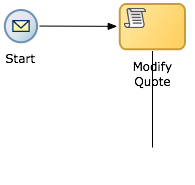
The signal start event is similar to a message start event in that it is based on communication from another process or service. However, the message start event responds to a message sent to a specific process. In contrast, the signal start event is a response to a signal broadcast to multiple processes.
Signals can be broadcast from a BPMN process using the signal throw event. Using a combination of signal throw and signal start events, you can invoke multiple processes simultaneously.
The signal start and throw events are generally added to a process by process developers. For information on implementing the signal throw event, see "Introduction to Communicating Between Processes Using Signal Events" in the Oracle Fusion Middleware Modeling and Implementation Guide for Oracle Business Process Management.
Figure 6-8 shows the default notation for the signal start event.
The timer start event triggers the creation of a process instance based on a specific time condition. You can configure the timer start event to trigger a process instance based on the following:
A specific date and time. For example, a process could be triggered on December 31, at 11:59 PM.
A recurring interval. For example, a process could be triggered every 10 hours, 5 minutes, 32 seconds.
Figure 6-9 shows the default notation for the timer start event.
The none end event is used to mark the end of a process path. When a token reaches a none end event, it is consumed. If there are no other tokens within the process instance, the instance is complete.
The none event is used when your process is not required to perform any action after it completes. It can also be used as a place-holder by process analysts, to be changed later during implementation by a process developer.
Figure 6-10 shows the default notation for the none end event.
The none end event is always used to mark the end of a subprocess and event subprocess.
Figure 6-11 shows an example of the none end event within the Sales Quote example process. In this example, the Sales Quote service task is used to perform the task of saving information about the sales quote to a database.
Figure 6-11 The None End Event within the Sales Quote Example Process
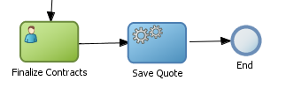
Since no other work must be performed when the token reaches the end of a process, a none end event is used. After all process tokens reach the none end event, the process instance completes.
The end error event is used when your the end of a process is the result of some error condition.
Errors end events are normally used with the error boundary event. The error boundary event is used to alter the process flow based on a specific error. This flow usually ends using an error end event. See Section 6.8.3, "Introduction to the Error Catch Event" for more information on using the error intermediate event.
Figure 6-12 shows the default notation for the error end event.
For information implementing the error end event, see the Oracle Fusion Middleware Modeling and Implementation Guide for Oracle Business Process Management.
The message end event is used to send a message to another process or service when the process is completed. The message end event is always used with either a message start event or message catch event.
Note:
When creating a process that has multiple end events, you must ensure that any tokens that reach a message end event were created by a message start. For example, you cannot use a message end event to end a process instance initiated by a timer start.
Figure 6-13 shows the default notation for the message end event.
For information on how implement message throw events, see "Communicating With Other BPMN Processes and Services Using Message Events" in the Oracle Fusion Middleware Modeling and Implementation Guide for Oracle Business Process Management.
The terminate end event is used to immediately terminate a process. When a terminate end event is reached, the process ends immediately. There is no error handling or additional clean up performed.
Most business applications require interaction from process participants within your organization. This interaction can be as simple as entering information into a form or can involve multiple work flows and multiple users.
This section describes the BPMN flow objects that are used to model how process participants interact with your business processes.
Many end-to-end business processes require human interactions with the process. For example, humans may be needed for approvals, exception management, or performing activities required to advance the business process.
Oracle Human Workflow provides comprehensive support for human participation by providing the following features:
Human interactions with processes, including assignment and routing of tasks to the correct users or groups
Deadlines, escalations, notifications, and other features required for ensuring the timely performance of a task (human activity)
Organization, filtering, prioritization, and other features required for process participants to productively perform their tasks
Reports, reassignments, load balancing, and other features required by supervisors and business owners to manage the performance of tasks
For more information see the Oracle Fusion Middleware Developer's Guide for Oracle SOA Suite.
Human Tasks are a component of Oracle Human Workflow. Human tasks enable you to interleave human interactions with connectivity to systems and services within an end-to-end process flow. Human tasks are responsible for handling all interactions with users or groups participating in the business process. They do this by creating and tracking tasks for the appropriate users in the organization. Users typically access tasks through a variety of clients, including the Oracle BPM Worklist application, E-mail, portals, or custom applications.
Human tasks enable process developers to define how process participants interact with process-based applications created using the Oracle BPM and SOA suites.
Using Human Tasks, process developers can define the interface and workflow for end-user interaction by creating the following:
Human Tasks are reusable services that can be used within other processes that require the same UI.
Roles and assignments
Deadlines and escalations
Presentations
Human tasks are created using Oracle BPM Studio.
Note:
In Business Process Composer, human tasks can be used in projects and project templates created in BPM Studio. You cannot create or edit Human Tasks in Business Process Composer.
The user task represents a part of your process where a process participant is required to perform work. This can be a simple interaction, such as entering a form, or part of a more complicated workflow that requires input from multiple process participants.
Figure 6-14 shows the default notation for the user task.
In the Oracle BPM Suite, process participants interact with your business application using the Process Workspace. The specific user interface elements, including the screens and panels that process participants see, are created using Oracle Human Tasks.
When designing a process, process analysts often only add the user task to a process diagram. Process developers then create the necessary Human Tasks and implement them as part of creating the overall process-based business application.
When a token reaches a user task, the corresponding Human Task is performed. The token waits until the Human Task is completed before continuing to the next flow object.
For information on how implementing user tasks, see "Using Human Tasks" in the Oracle Fusion Middleware Modeling and Implementation Guide for Oracle Business Process Management.
Like other flow objects, the user task may contain incoming and outgoing data associations.
User tasks may also contain incoming and default outgoing sequence flows.
Note:
Using Business Process Composer, you can only assign Human Tasks to User Task that were created as part of a project template in Oracle BPM Studio. You cannot create new human tasks or edit existing ones.
In the Sales Quote demo process, the Enter Quote task, shown in Figure 6-15, represents the work of entering information about the quote.
After the end-user enters information about the sales quote the process flow passes through the outgoing sequence flow to the next flow object in the process.
Oracle BPM Studio enables you to add interactive activities to a process directly from the component palette. Interactive activities are short cuts based the task routing and approval features of Oracle Human Workflow. See "Getting Started with Human Workflow" in Oracle Fusion Middleware Developer's Guide for Oracle SOA Suite for more information.
Note:
Interactive activities are not available from the Business Process Composer component palette. To model user interaction with Business Process Composer, you can add a generic user task to your process. Interactive activities can later be implemented later by process developers using Oracle BPM Studio.
Table 6-2 shows the interactive activities are available from the Oracle BPM Studio component palette:
Table 6-2 Interactive Activities
| Pattern | Description |
|---|---|
|
Complex |
Uses a complex routing flow that is defined within the Human Task. |
|
Management |
Uses the management chain pattern where the assignee is set to the management chain pattern for the process participant belonging to the group or role assigned to the swim lane. |
|
FYI |
Bases assignment on the participant, role, or group defined in the swimlane. Similar to the user interactive activity, but the FYI activity does not wait until completion before continuing. |
|
Group |
Uses the group vote pattern. The assignee for the is automatically set to the role/group associated with the Lane. This interactive activity can only be added to swimlanes that are assigned to roles or groups. |
|
Initiator |
The initiator pattern is used to create a process instance. |
Using Oracle BPM Studio, add Human Tasks to the business catalog. Process analysts can use these in Business Process Composer when working with projects created from project templates.
Note:
You cannot create or edit Human Tasks using Business Process Composer. Human Tasks are created using Oracle BPM Studio
When adding the user task to a project template to be used within Business Process Composer, you should follow these guidelines:
Process developers must create any required Human Task services within Oracle BPM Studio before using the template in Business Process Composer. Human Tasks can implemented within a user task or this implementation can be performed when editing the project based on the project template.
However, if the Human Task service is being implemented for user task that is sealed within a project template, you must also perform the implementation before using the project template in Business Process Composer.
The manual task represents a task performed by process participants that is outside of the scope of Oracle BPM. Manual tasks are used as placeholders within your process to show work that is not managed by the BPMN service engine at run time. Additionally, manual tasks do not appear in the Process Workspace application.
Note:
Manual tasks are not managed by Oracle BPM. The Oracle BPM run time does not track the start and completion of the manual task.
Figure 6-16 shows the default notation for the manual task.
Manual tasks can only have one default incoming and one default outgoing sequence flow.
Unlike most BPMN flow objects, the manual task does not allow you to manipulate data objects. Data objects associated with the previous flow element are passed through as-is to the next flow element.
In the context of the Sales Quote example process, a manual task could be added for printing and signing a copy of a formal contract as shown in Figure 6-17.
In this example, signing the formal contract is something that you may want to explicitly show as part of your business process. However, since it is not managed by the BPMN Service Engine, a manual task is used.
Oracle BPM enables you to define interactions across business processes within a process-oriented application. The following sections describe the BPMN flow objects used to model communication between processes.
This section describes how to use these flow objects to create process models using Business Process Composer. For information on how to implement these flow objects within a process-based application, see the Oracle Fusion Middleware Modeling and Implementation Guide for Oracle Business Process Management.
The service task enables you to communicate with other processes and services. Process analysts can add the service task when they know that a process must invoke an external service or process.
Process developers can then implement the necessary services. You can use the service task to invoke the following:
Other BPMN processes
BPEL processes
SOA service adapters
Mediators that are exposed as services
The service task has similar behavior to the send and receive task pair and the message throw and catch event pair. The primary difference is that the service task is used to invoke processes and service synchronously. When the service task invokes a process or service, the token waits at the service task until a response is returned. After the response is received, the token continues to the next sequence flow in the process.
See "Using Service Tasks to Invoke Synchronous Operations in Services and BPMN Processes" in the Oracle Fusion Middleware Modeling and Implementation Guide for Oracle Business Process Management for more information on how to implement the service task with these types of processes and services.
Figure 6-18 shows the default notation for the service task.
Figure 6-19 shows an example of the service task used to save the finalized sales quote to a database.
Figure 6-19 The Service Task within the Sales Quote Example Process

The notification task is similar to the service task. It uses a predefined service to perform different types of notification. You can use expressions to determine the users or groups who will receive notifications generated by the notification task.
For more information on implementing the notification task see Oracle Fusion Middleware Modeling and Implementation Guide for Oracle Business Process Management.
These different types of notification are:
IM: Send an instant message to a user or group. Figure 6-20 shows the default notation of the IM notification task.
Figure 6-20 The Instant Message Notification Task
Email: Sends an E-mail a user or group. You can also include E-mail attachments. Figure 6-21 shows the default notation of the email notification task
SMS: Sends an SMS message to a user. Figure 6-22 shows the default notation of the SMS notification task
Voice: Sends a voice mail to a user. Figure 6-23 shows the default notation of the voicemail notification task.
Figure 6-23 The Voicemail Notification Task
User: Sends a notification to a user based on the available notification types. For example, if a user has both a voicemail and email configured, the notification task will send both. Figure 6-24 shows the default notation of the User notification task.
The call activity allows you to call a reusable process from within the current process. The process being called becomes a child process of the calling process. When calling a reusable process, the call activity of the parent process waits until the child process completes before continuing.
Figure 6-25 shows the default notation for the call activity.
Data objects of the parent process are not automatically available to the reusable process. Data objects must be passed to and from the child process using argument mapping of the call activity.
Oracle BPM supports a type of process called reusable processes. In BPMN terminology, this is sometimes referred to as a reusable subprocess. Reusable processes allow you to create processes that can be called from other BPMN processes.
Reusable processes allow you to create processes that can be called from other BPMN processes. For example all your processes may need to charge a credit card, so you can create a charge credit card reusable subprocess
Reusable processes have the following characteristics:
Must start with one none start event
Can contain multiple end events.
Can only be called by other BPMN processes.
The following figure shows how control flow is passed to a child process and back to the parent process.
A token reaches the call activity in the parent process
A new instance of the child process is created.
The child process continues running until an end event is reached or an error occurs.
The process flow returns back to the call activity in the parent process.
Flow of the main process continues.
The send task sends a message to a system or process outside the current process. Once this message is sent, the task is complete and running of the process continues to the next task in the process flow.
The send task is frequently paired with the receive task to invoke a process or service and receive a response in return. The send and receive tasks are used to invoke processes and services asynchronously. If you are invoking a process or service synchronously, use the service task.
Note:
The send and receive tasks perform similar functionality to the throw and catch message events. However, you cannot use the send task to invoke a process that is initiated with a message start event.
Figure 6-26 shows the default notation for the send task.
For information on implementing the send task to invoke a process or service, see "Using Send and Receive Tasks to Define a Synchronous Operation in a BPMN Process" in the Oracle Fusion Middleware Modeling and Implementation Guide for Oracle Business Process Management.
See Chapter 6, "Using the Send and Receive Tasks to Communicate Between Processes" for information on using the send and received tasks to communicate between processes.
In contrast to the send task, the receive task waits for a message from a system or process outside the current process. Once this message is received, the task is complete and running of the process continues to the next task in the process flow.
Figure 6-27 shows the default notation for the receive task.
For information on implementing the send task to invoke a process or service, see "Using Send and Receive Tasks to Define a Synchronous Operation in a BPMN Process" in the Oracle Fusion Middleware Modeling and Implementation Guide for Oracle Business Process Management.
See Section 6.4.6, "Using the Send and Receive Tasks to Communicate Between Processes" for information on using the send and received tasks to communicate between processes.
You can use the receive task to trigger the start of a process. This is useful when you want to invoke a process from another process using a send task.
To start a process using the receive task, the following conditions must be met:
The receive task is preceded by an none start event.
Your process does not contain any other start events.
The Create Instance property is enabled.
The following section describes how to use the send and receive tasks to communicate between processes.
You can use the send and receive tasks to invoke another BPMN process and receive messages back from it. Processes that begin with a receive task and contain a send task are exposed as services that can be used by other process and services within an Oracle BPM application.
Figure 6-28 outlines the basic behavior when using send and receive tasks to invoke a process and receive a response.
Figure 6-28 Using the Send and Receive Tasks to Communicate Between Processes
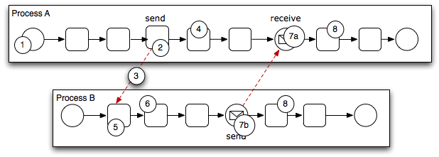
The following steps outline a possible scenario when using the send and receive tasks to communicate between processes.
Process A is invoked.
A token of Process A reaches the send task.
The send task invokes Process B.
This is defined by the implementation for the send task.
The token of process A proceeds to the next flow object in the process.
The receive task initiates a process instance of Process B.
The receive task must have the Create Instance property defined. See Section 6.4.5.2.
The newly created token proceeds through process B.
Depending on the specific behavior of your process, the following scenarios may occur:
If the token of Process A reaches a receive task paired with a send task from Process B, the token of process A waits until a response is received. After the response is received, the token of Process A continues to the next flow object.
If the token of Process B reaches a send task paired with a receive task in Process A, Process B sends a response to Process A. The token of Process B continues to the next flow object.
Both processes continue running. You can use subsequent send and receive pairs to define subsequent communicate between the two processes.
The message throw event enables you to send a message to another process or service.
Figure 6-29 shows the default notation for the message throw event.
The throw message event can be used to invoke the following types of processes and services:
Other BPMN processes
BPEL processes
SOA service adapters
Mediators that are exposed as services
Process analysts may add message throw events to a process to define where a process must invoke another process or service. However, process developers are typically responsible for implementing the connectivity with other processes. Additionally, they are typically responsible for creating and implementing the services invoked by the message throw event.
For information on how implement message throw events, see "Communicating With Other BPMN Processes and Services Using Message Events" in the Oracle Fusion Middleware Modeling and Implementation Guide for Oracle Business Process Management.
Message throw events are often used to invoke other BPMN processes by calling the message start event of another process. See Section 6.2.3, "Introduction to the Message Start Event" for more information.
Message throw events are also frequently used with message catch events to receive a response from the process or service invoked. However, they are always used asynchronously. After the message throw event sends a message to another process or service, the toke immediately moves to the next flow object of the process.
If your process receives a response synchronously, you should use the service task to invoke the process or service. See Section 6.4.1, "Introduction to the Service Task" for more information.
Note:
The send and receive tasks perform similar functionality to the throw and catch message events. However, you cannot use the message throw event to invoke a process that is initiated with a message receive task.
The message catch intermediate event enables you to receive a message from another process or service.
Figure 6-30 shows the default notation for the message catch event.
The message catch event is frequently used with the message throw event to communicate with another BPMN process. See Section 6.4.9 for information on how message throw events with message catch event.
For information on how implement message throw events, see "Communicating With Other BPMN Processes and Services Using Message Events" in the Oracle Fusion Middleware Modeling and Implementation Guide for Oracle Business Process Management.
You can use combinations of throw and catch events to invoke and communicate with other BPMN processes. When using a throw event to invoke another process, the following conditions must be met:
The process being invoked must be an asynchronous process. Although you can use a message throw to invoke a synchronous process, there is no mechanism for catching messages synchronously from the process.
If you invoke a synchronous process you should use the service task. See Section 6.4.1, "Introduction to the Service Task" for more information.
The first time you use a throw event it must be paired to the message start event of the other process. This is required to trigger the process instance. After the instance has been trigger, you can use subsequent message throw events that are caught by the second process.
Processes that begin with a message start and end with a message end event are exposed as services that can be used by other process and services within an Oracle BPM application.
Processes invoked from another process are not considered child processes. This is important to consider when designing processes that use the terminate end event as a process end point. For example, a terminate event in the calling process does not terminate processes invoked with a message throw event
Figure 6-31 shows the basic behavior when using throw and catch event to invoke a process and receive a response.
Figure 6-31 Using Message Throw and Catch Events Between Processes
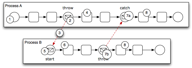
The following steps outline a possible scenario when using the message throw and catch events to communicate between processes.
Process A is invoked.
The token of Process A reaches a message throw event that is configured to invoke Process B.
The message throw event sends a message to the message start event of Process B.
The token of Process A proceeds to the next flow object.
The message start event triggers an instance of Process B.
The newly created token proceeds through Process B.
Depending on the behavior of your process, the following scenarios may occur:
If the token of Process A reaches a catch event paired with a throw event from Process B, the token of process A waits until the message is received. After the message is received, the token of Process A continues to the next flow object.
If the token of Process B reaches a throw event paired with a catch event in Process A, Process B throws a message to Process A. The token of Process B continues to the next flow object.
Both processes continue running. You can use subsequent catch and throw pairs to define subsequent communication between the two processes.
This section describes how to use the business rule task to incorporate Oracle Business Rules within your business processes. See Chapter 16, "Using Business Rules" for information on working with Oracle Business Rules using Business Process Composer.
Business rules are statements that describe business policies or describe key business decisions.
The business rule task enables you to incorporate Oracle Business Rules within your process.
Figure 6-32 shows the default notation for the business rule task.
There are two primary use cases for incorporating Oracle Business Rules within your business process.
Using Structural Rules
Structural rules allow you to perform calculations used within your business process. For example, you could use a business rule to calculate a credit score.
Using Operative Rules
Operative rules are used to make changes to the flow of your process. A typical use of an operative rule is to check perform a check of rule conditions within the rules catalog. Then, as part of the output data association, assign a value to a data object using an expression.
In this scenario, the business rule task is immediately followed by a gateway which is used to branch the process path according to the value of the data object.
See Section 6.5.2.1, "The Business Rule Task in Context" for information on how an operation rule is used within the Sales Quote example project.
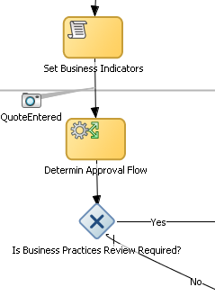
Figure 6-33 shows an example of the business rule task within the Sales Quote example process.
Figure 6-33 The Business Rule Task within the Sales Quote Example Process
This section describes how to use sequence flows to define the behavior of your business process.
Sequence flows define the order or sequence that work is performed within a process. Sequence flows connect the flow objects within your process and determine the path a process token follows through your process.
Incoming sequence flows are the sequence flows that flow into a flow object. Outgoing sequence flows are the sequence flows that determine the process path out of a flow object.
Most flow objects contain both incoming and outgoing sequence flows. Exceptions to this are start and end events. Start events can only contain outgoing sequence flows. End events can only contain incoming sequence flows. Additionally, event subprocesses do not have either incoming or outgoing sequence flows.
Unconditional sequence flows represent the normal path between two flow objects. Default sequence flows are displayed as an arrowed line as shown in Figure 6-34.
Figure 6-34 The Unconditional Sequence Flow
Most flow objects can contain only one default out going sequence flow. Only parallel gateways can contain multiple unconditional sequence flows which represent the parallel paths of your process.
Exclusive, inclusive, and conditional gateways cannot have unconditional outgoing sequence flows. These gateways use conditional and default sequence flows to determine the flow of your process.
Conditional sequence flows are used to control the flow of a process based on certain conditions. Like unconditional sequence flows, conditional sequence flows are displayed by an arrow lined arrow.
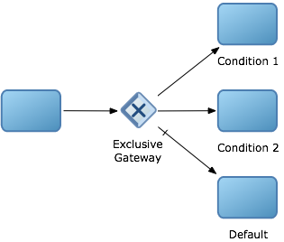
Figure 6-35 shows two outgoing conditional sequence flows and a default sequence flow.
Figure 6-35 Conditional and Default Sequence Flows
Not all flow objects can use outgoing conditional sequence flows. Only the following types of gateways can have outgoing conditional sequence flows:
Exclusive gateways
Inclusive gateways
Conditional gateways
Event-based gateways
The conditions used within a conditional sequence flow are defined using expressions. See Section 26.1, "Introduction to Expressions in Oracle BPM" for information on using the expression editor to define expressions.
Like conditional sequence flows, default sequence flows are used as outgoing sequence flows to exclusive, inclusive, and conditional gateways. Default sequence flows represent the path your process will take out of these gateways when none of the conditions evaluate to true.
Default sequence flows are represented by an arrowed line with a tic mark on one end as shown in Figure 6-35.
This section describes how to use gateways to control process flow and behavior.
Gateways are flow elements that define the flow of your process. Gateways determine the path a token takes through a process. They define control points within your process by splitting and merging paths.
When possible, gateways are used for paths that are exceptions to or deviate from the default path of the process.
The following gateways require a split-merge pair:
Parallel Gateway
Inclusive Gateway
Complex Gateway
When you add one of these gateways to a BPMN process, Oracle BPM Studio automatically creates the split and merge flow objects.
Although the merge portion of the gateway is required, you do not have to ensure that all paths out of the split return to the merge.
Although it is possible to have process paths that split at a gateway without merging through the gateway, this is not usually good practice. For more details on the merge behavior of gateways, see the following sections for each gateway type.
Note:
If you delete the merge gateway from a process, the corresponding split is also deleted.
The exclusive gateway enables you to split your process into two or more paths. However, the process only continues down one of these paths even if multiple outgoing sequence flows are present. Exclusive gateways can have conditional outgoing sequence flows and must have at least one default outgoing sequence flow.
You can define expressions that are used to determine if your process continues down a conditional sequence flow. If your process has multiple outgoing sequence flows for an exclusive gateway, you can define the order in which they are evaluated. The order of evaluation is configured in the properties of the exclusive gateway.
If you have an exclusive gateway where more than one conditional evaluates to true, the process will continue down the first conditional sequence flow determined by this order.
Unlike other gateways, the exclusive gateway does not require a corresponding merge to be explicitly defined in your process after splitting.
Figure 6-36 shows the default notation for the exclusive gateway.
Figure 6-37 shows an example of the exclusive gateway used within the Sale Quote example process. Here, the exclusive gateway is used to evaluate whether a review of business practices is required.
Figure 6-37 The Exclusive Gateway within the Sales Quote Example Process
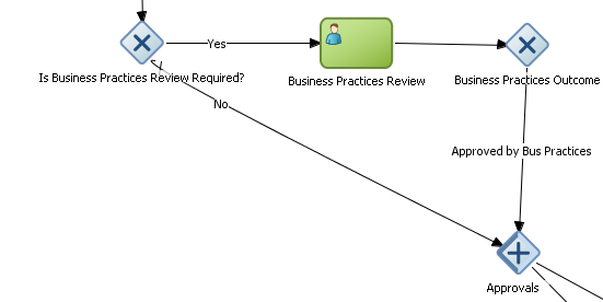
This evaluation is determined by the expression defined for the outgoing conditional sequence flow. If this evaluates to true, then the process flow proceeds down the Yes path. If it evaluates to false, then the process flow proceeds down the path of the default outgoing sequence flow.
When a token reaches an exclusive gateway the outgoing conditional sequence flows are evaluated until one of them evaluates to true. You can define the specific order in which these are evaluated by configuring a property for the exclusive gateway.Based on this configuration, when the first conditional sequence flow evaluates to true, the token moves down this outgoing sequence flow to the next flow object. If you have multiple outgoing conditional sequence flow you can determine the order in which they are evaluated.If none of the outgoing conditional sequence flows evaluate to true, then the token moves down the default outgoing sequence flow. Therefore, you must define a default outgoing sequence flow for the exclusive gateway.
The exclusive gateway can also merge incoming sequence flows. However, there is no synchronization with other tokens that may be coming from other paths within the process flow.
Note:
If other tokens arrive at an exclusive gateway merge, then they are also passed through as is. If you are synchronizing tokens or perform evaluations on incoming sequence flows, you should use a different type of gateway.
The inclusive gateway enables you to split your process into two or more paths. Unlike the exclusive gateway, however, a token may flow down one or more of these paths depending on how the outgoing conditional sequence flows are evaluated.
You can have multiple outgoing conditional sequence flows for an inclusive gateway split. You must define at least one default sequence flow.
Figure 6-38 shows the default notation for the inclusive gateway split.
Figure 6-38 The Inclusive Gateway (Split)
Figure 6-39 shows the default notation for the inclusive gateway merge.
Figure 6-39 The Inclusive Gateway (Merge)
The inclusive gateway splits a process similar to the exclusive gateway, but enables tokens to proceed down multiple outgoing sequence flow. When a token arrives at an inclusive gateway, the expressions of its conditional sequence flows are evaluated.
Next, a token is generated for each of the conditional sequence flows that evaluates to true. A token is generated for the default sequence flow only if none of the conditional sequence flows evaluates to true.
These tokens are merged at the merge of the inclusive gateway. When a token reaches the merge gateway, it waits until all of the tokens generated by the split have reached the merge. Once all of these tokens have reached the merge of the inclusive gateway, the merge is complete and the token continues to the next sequence flow after the gateway.
The parallel gateway enables you to split your process into two or more paths when you want your process flow to follow all paths simultaneously. The parallel gateway is useful where your process must perform multiple tasks in parallel.
Figure 6-40 shows the default notation for the parallel gateway split.
Figure 6-41 shows the default notation for the parallel gateway merge.
The Sales Quote example process uses a parallel gateway during the approval stage of the process. Figure 6-42 shows how the parallel gateway is used to perform two process paths simultaneously.s
Figure 6-42 Example of a Parallel Gateway
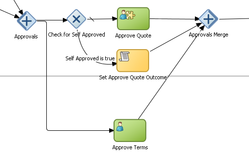
In this example, two different process paths are executed at the same time.
When a token reaches a parallel gateway, the parallel gateway creates a token for each outgoing sequence flow. The split of the parallel gateway does not evaluate outgoing sequence flows.
You can also use the parallel gateway to merge process paths split by the parallel gateway. The merge of the parallel gateway waits for a token to arrive from each of the incoming sequence flows. After all tokens arrive, only one token is passed to the outgoing sequence flow.
Note:
You should design your process so that a token arrives for each incoming sequence flow for the merging parallel gateway. If you do not, your process can freeze if the merge is expecting tokens that do not arrive.
The complex gateway splits a process similar to an inclusive gateway. However, it enables you to define a condition that determines if the instance can continue even if not all of the tokens have arrived at the complex gateway merge.
For example, you can configure a complex gateway to continue after two or more tokens have arrived. If only two out of the possible conditions in the inclusive gateway evaluate to true the process instance continues to the next activity. However since the inclusive gateway immediately evaluates all the conditional sequence flows, all of the flow objects in these process paths are also run.
Figure 6-43 shows the default notation for the complex gateway split.
Figure 6-44 shows the default notation for the complex gateway merge.
The event-based gateway enables you to branch your process flow based on the possibility that an event may occur. Depending on the context, this may be one of several types of events.
The event-based gateway enables you to anticipate the possibility that several types of events may occur at a specific point in your process. It is similar to the exclusive gateway, but instead of choosing a path based on expressions, the event-based gateway chooses a path based on the occurrence of an event within your process.
For example, in an order processing process, you may reach a point in your process when there is no stock currently available. The process may need to wait until stock is available, but cannot wait indefinitely. By using an event-based gateway, your process can wait for a message saying new stock has been received (using a message catch event) or it can continue if no message is received after a certain amount of time has passed (using a timer event)
Figure 6-45 shows the default notation for the event-based gateway.
The event-based gateway is different than other gateways in that decisions about process flow are based on an event rather than data-specific conditions.
The event-based gateway is composed of the following:
The event-based gateway
Two or more target events. These can be of the following types:
Message catch events
When initiating a process using a message catch event, the process must be invoked using a message throw event.
Timer catch events
Generally only one timer event is used following an event-based gateway.
Receive tasks
You can use the receive task to initiate a process instance following an event-based gateway. However the process must be invoked from a send task within the calling process.
Note:
You cannot mix message events and receive tasks within the same event-based gateway.
The target elements can only have incoming sequence flows from the event-based gateway. They cannot have sequence flows from other parts of the process.Although the event-based gateway enables you to plan that multiple events may occur in your process, within the process instance, only one event is triggered. When the first event in the event-based gateway is triggered, then the path that follows that event is followed.
By default, when you add an event-based gateway to a process, it is created with a timer and message catch event.
Note:
If you delete an event-based gateway, any outgoing sequence flows are also deleted. However, the associated events are not deleted.
You can also use an event-based gateway at the beginning of a process to create a new process instance. This is similar to having multiple start events within a process.
To enable an event-based gateway to create a new process instance, you must ensure the following:
You have enabled the Initiate property of the event-based gateway.
There are no incoming sequence flows to the event-based gateway.
Although the event-based gateway can be used to create a new process instance, it does not accept data input from another process. Any data that must be passed to the process instance must be configured using the target events.
This section describes intermediate events and describes how to use them to control the flow and behavior of your process.
Unlike start and stop events, intermediate events occur during the flow of your process.
There are two types of intermediate events:
Normal flow events
Normal flow events occur within the normal flow of your process.
Boundary events
Boundary events trigger an interruption with your process. Boundary events are associated with flow objects and can be configured to interrupt their normal behavior.
Boundary events behave similar to sequence flows in that they are used to determine the path a process takes between flow objects.
Boundary events can be divided into two types: interrupting and non-interrupting.
Timer catch events enable you to control the flow of your process using a time condition. Possible uses of the time catch event include:
Creating a delay before running an activity.
Configuring a deadline for an activity.
Configuring a deadline for a process.
Triggering additional activities after an elapsed time.
Figure 6-46 shows the default notation for the timer catch event.
You can use timer event as boundary events on an activity. Timer events can be defined as either interrupting or non-interrupting boundary events.
When an interrupting timer event fires, the token leaves the main process flow to follow the flow the timer defines. The flow that an interrupting can return directly to the main process flow.
When an non-interrupting event fires, a copy of the token is created and passes through the flow the timer event defines. The flow that a non-interrupting event defines cannot return to the main process flow.
Error catch events are intermediate events used to handle an error that occurs within your process flow. Error catch events are always used as boundary events and can be attached to the following:
Service Tasks
User Tasks
Send Tasks
Receive Tasks
Script Tasks
Rules Tasks
Event Subprocesses
Subprocesses
Error catch events are always interrupting, meaning that they interrupt the normal flow of a process.
Figure 6-47 shows the default notation for the error catch event attached as a boundary event on a service task.
Figure 6-47 The Error Catch Event as a Boundary Event on a Service Task

When a service or process fails with an error, the error catch event triggered. This causes the process flow to follow the path of the outgoing sequence flow of the error catch event.
You can use this flow to define how you handle the error. This is generally handled in two ways:
The process flow returns to the main process flow. Any work that must be performed is handled within the error process flow before returning back to the main flow.
Note:
If the boundary event is non-interrupting, the boundary flow cannot return to the main flow.
The process flow from the error ends in an error event. The process is terminated immediately. Process control is passed to the service or process that initiated the process.
In Oracle BPM, subprocesses are embedded subprocesses. Subprocesses are contained as part of the parent subprocess. Subprocesses must begin with a none start event and must end with a none end event.
Subprocesses can be expanded or collapsed. Figure 6-48 shows how a collapsed subprocess appears within a process.
Figure 6-48 Example of a Collapsed Subprocess

Figure 6-49 shows how an expanded subprocess appears within a process. When a subprocess is expanded, you can edit the flow objects within. You can also click and drag the edge of the subprocess window to make the window larger or smaller.
Figure 6-49 Example of an Expanded Subprocess
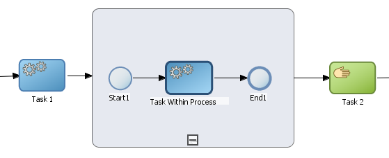
Like other types of processes, subprocesses have start and end events and contain their own flow. A subprocess must begin with a none start event and end with a none end event. Subprocesses do not contain swimlanes.
Subprocesses also behave like activities. They can have incoming and outgoing sequence flows. They also contain data associations that define the data objects used within the subprocesses.
Subprocesses can also contain timer, message, and boundary events.
If necessary, your process can contain nested subprocesses. However, you should use nested subprocesses only when necessary to make your process more readable.
The flow objects within a subprocess cannot have sequence flows that connect to flow objects outside the subprocess.
Like other flow objects, subprocesses have incoming and outgoing sequence flows.
Figure 6-50 show an example of a subprocess. In this example, a subprocess is used to group the service task used to process a sales quote.
This section describes how to use the script task to change the values of data objects within your process.
The script task is used to change values of data objects within your process. The script task is used when you want to model this explicitly this within your business process or when you must change the values of data objects outside of another flow object. It is often used to set initial values of data objects at the beginning of a process.
Figure 6-51 shows the default notation for the script task.
Script tasks are generally added to a process by process developers who are responsible for defining the behavior of data objects within a process and process-based application.
Figure 6-52 shows two examples of the script task used at the beginning of the Sales Quote example process. The Sales Quote example process uses a script task to set initial values for data objects at the beginning of a the process and to set values for several business indicators.
Figure 6-52 The Script Task within the Sales Quote Example Project
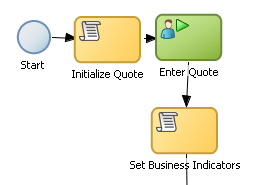
Project data objects are data objects that you define in a project, all the processes in that project have those data object defined, though the value changes according to the process using them. In addition, the engine stores the value of those marked as business indicators to the process analytics databases if the project is configured to use them.
Figure 6-53 shows the data associations used to set initial values for the business indicators.
Figure 6-53 Data Associations Used by the Set Business Indicators Script Task
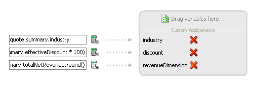
As with other flow objects that accept data associations, you can use expressions to change the values of data objects. Figure 6-54 shows how an expression is used to alter the value of the discount project variable.
Figure 6-54 Expression Used to Change the Value of Discount Project Variable

You can measure process performance using measurement marks. Measurement marks enable you to measure a business indicator of type measure at a certain point in the process or in a section of the process.
For more information on using measurement marks and the Process Analytics database, see "Using Process Analytics" in the Oracle Fusion Middleware Modeling and Implementation Guide for Oracle Business Process Management.
A measurement mark stores the following data into the Process Analytics databases:
The value of the process default measures
The value of the measure business indicators associated to that measurement mark
The value of the dimensions defined in the process
You can use one measurement mark to measure multiple business indicators.
When storing the value of a measure business indicator, the BPMN Service Engine also stores the value of the dimensions you defined in your process. Later on, when you build the dashboards to monitor your process, you can use these dimensions to group the values into different categories. For example, in the Sales Quote process you might want to view the total amount of quotes approved by region.
The types of measurement marks you can define are:
Single Measurement
Interval Start
Interval Stop
You can add measurement marks to your business processes by dragging the from the component palette to the process editor canvas.
To add a single measurement mark to a process:
Open the BPMN process.
In the Component Palette, expand the Artifacts section and select from following:
Start measurement mark
End measurement mark
Single measurement mark (Snapshot)
Place the measurement mark near the sequence flow where you want to measure a business indicator. When the sequence flow turns blue, drop the measurement mark.
Right-click the measurement mark and select Properties.
In the Name text-field, enter a name to identify the measurement mark.
In the Business Indicators section, select a business indicator from the list of available business indicators and move it to the Selected list using the arrows between the two lists.
Note:
You can measure multiple business indicators in the same measurement mark.
Note:
If you do not select a business indicator, then this measurement mark only stores the value of the default business indicators. If you want to add a business indicator without leaving the Measurement Mark Properties dialog, then you can click the New button under the Selected list.
Click OK.
This section describes how to use Guided Business Processes in Business Process Composer.
Guided Business Processes provide a guided visual representation of a process flow, improving the user experience by providing process participants with an encapsulated hierarchical view of the business process.
Guided Business Processes enable process designers to direct process participants to complete a business process through a set of guided steps associated with the process. By following the steps outlined in a Guided Business Process, process participants require less training to complete a business process, and the results of the process are more predictable.
A Guided Business Process is modeled as an activity guide that is based on a business process. The Activity Guide includes a set of Milestones. A milestone is a contained set of tasks that the process participant has to complete. A milestone is complete when the user successfully runs a specific set of tasks in the milestone.
Each milestone is a specific set of human workflow tasks. Each human workflow task is itself a task flow that may require the collaboration of multiple participants in various roles. Depending on the nature of the task flows, a participant may save an unfinished task flow and resume it at a later time.
Using Business Process Composer, you can configure Guided Business Processes and add milestones to them.
To configure the activity guide for a project:
In the Project Navigator, expand the project where you want to configure the activity guide.
Right-click Activity Guide, then select Configure.
Enter a title for the Activity Guide.
Configure the following optional properties:
Display Mode: Determines how milestones and tasks within the guided business process display links. If the milestone and tasks use another configuration then the guided business process configuration is ignored.
Possible values are:
Always: Always display the milestone and task links for all the milestones in this guided business process.
When Instantiated: Display the milestone and task links only when one or more of the user tasks in the milestone are instantiated, for all the milestones in the guided business process.
Task Access: After the task is completed, the guided business process uses this configuration to display the links. If the task mode is active only, the tasks links are grayed out. If the task mode is any state, the tasks links remain enabled and a message appears when you try to run the task.
Possible values are:
Active Only: The link to the task is enabled only when the task is active and the user can update it. When you complete the task the link to the task is grayed out.
Any State: The link to the task is always enabled after you instantiate the task, even after you complete the task.
Root Process: Determines the process used for this Activity Guide. You can only define one guided business process per BPM project. This process is the root process.
Description: Provides an optional description for the Activity Guide.
Click Save in the project toolbar.
To Create a New Milestone:
In the Project Navigator, expand the project where you want to configure the activity guide.
Right-click Activity Guide, then select Configure.
Click New Milestone.
Select the milestone you just created from the list.
Configure the milestone as necessary.
Click Save in the project toolbar.
To Add a User Task to a Milestone:
Open the process where you want to add a milestone.
Right-click the user task you want to add to a milestone.
Select a milestone from the list, then click OK.