| Oracle® Communications IP Service Activator System Administrator's Guide Release 7.2 E39366-01 |
|
|
PDF · Mobi · ePub |
| Oracle® Communications IP Service Activator System Administrator's Guide Release 7.2 E39366-01 |
|
|
PDF · Mobi · ePub |
This chapter provides feature, administration, maintenance, and troubleshooting information for the Network Processor and its cartridges.
The Network Processor/Cartridge combination is implemented in a Oracle Communications IP Service Activator system, as shown in Figure 7-1.
Figure 7-1 IP Service Activator system with Network Processor and cartridges
More than one Network Processor can be installed in a distributed system, as long as each server contains only one Network Processor. A Network Processor can have multiple cartridges.
The Network Processor uses Activation Cartridges that include XML-based vendor-specific and service-specific definitions for a number of device types.
The Network Processor, with integrated cartridges, is a drop-in replacement for the existing Proxy Agent/Device Driver. Supporting an enhanced stateful activation model, the Network Processor uses a persistent store in the Oracle database to keep a record of the details and state of services deployed on devices.
The Network Processor component allows the introduction of service support on new device types or variants of existing types. You can develop new cartridges and configuration policies using the IP Service Activator SDK.
The following list describes features of the Network Processor/cartridge combination, including differences from the existing Proxy Agent/Device Driver implementation.
Scalability and performance: A number of features of the Network Processor/cartridge enhance the scalability and performance of IP Service Activator. Multiple Network Processors can each load an instance of the same cartridge, thereby allowing to scale up to a higher number of managed devices. The Network Processor/cartridge offers a reduction in the system restart time, and improves overall system stability.
Flexible development: The Network Processor provides multi-vendor capability, with vendor-specific pieces delivered as cartridges.
Component Manager: The Network Processor runs under the control of the Component Manager, just as Proxy Agents and Device Drivers do. The Component Manager is responsible for starting, stopping, and restarting the Network Processor, and for reporting component failures.
No three-way comparison: Unlike existing Device Drivers, the Network Processor does not perform a three-way comparison.
The main components of the Network Processor/cartridge are shown in Figure 7-2.
Figure 7-2 Network Processor, Cartridge Components and CLI Commands to Device
Figure 7-3 illustrates the flow of data through the Network Processor.
Figure 7-3 Network Processor Data Flowchart from the Interface to the Target Device
The main components are described as follows:
A Network Processor is a processing component that performs the conversion of user changes into a set of CLI commands for delivery to devices.
A Service model is a device-independent representation of service objects and their relationships. It resembles the information model configured by the user.
A Device model is a device-specific XML document derived from the service model. It contains a set of data elements that defines the complete device state.
A Cartridge is a vendor-specific implementation of a set of services for a given family of device types running the same operating system. It may be composed of multiple cartridge units.
A Cartridge unit defines an instance of specific, concrete, complete behavior (including command syntax) for a service or a set of services. It is applicable to device/OS combinations with identical CLI behavior. For more information see, "Capabilities and Options". A cartridge unit contains:
a service model transformation script (XQuery).
a device model schema definition (XML Schema). It governs the structure of the Device model.
a command generation script (XQuery). The output is the CLI, the set of commands specific to the target device type.
The Cartridge registry maps device type/OS combinations to cartridge units. When a transaction arrives, the Network Processor looks in the cartridge registry file (MIPSA_registry.xml) and selects a cartridge unit based on the supported device type and OS.
If you have a device type/OS combination that is not present in file MIPSA_registry.xml, you must create a new cartridge registry file, as outlined in "Creating or Editing a Cartridge Registry File".
The Policy Server takes user input and computes all its effects on the modeled network. For each device affected, if the device is managed by a Network Processor, the Policy Server sends the device-specific changes to the Network Processor. The Network Processor assembles an abstract service level model for the device, called the Service Model.
The Network Processor matches the device's type and IOS information against the Registry files in the cartridges to identify the specifics of handling this particular device. The Network Processor uses the specifications for transformation, validation, capabilities and options (among others) in the matching Registry entries to convert the device Service Model into one or more target Device Model documents. These documents represent the services as configured on the device.
The Network Processor compares the target documents with the last saved Device Model documents for this device and generates an annotated document that describes the changes. It again uses the matching Registry entries to convert this annotated document into commands - which are then dispatched to the device and recorded in the audit log.
If command delivery is successful, the target Device Model documents and the computed Service Model used are saved to the database, replacing the older saved documents. For a given device, there can be a maximum of one "current" set of documents, as identified by the document versions in the database.
If command delivery fails for whatever reason on the device, the Network Processor rolls back all commands delivered so far. It then isolates the failing command and attempts to undo the last change that triggered this command (and replace it with the last known successful state). The Network Processor then recomputes the commands to be delivered to the device and attempts the delivery again. This cycle is repeated until either all configuration changes have individually succeeded or failed. At that point, Network Processor raises faults in the Policy Server and GUI to indicate failure and provides more information on what failed and why.
Before pushing a new service, an audit of the device should always be performed to make sure that there is no conflicting configuration on the device.
The Network Processor changes only those configuration elements on the device that are indicated by the user input. Existing Device Drivers raise a flag when they find manual configuration on a device. The flag raised and the action taken (Delete, Warn and delete, or Fail and don't delete) depend on a setting configured during domain setup. The Network Processor does not raise these flags, nor does it delete any configuration when the device reports a conflict, regardless of the configured setting.
The Network Processor changes existing configuration on the device only if the device response is a success message, one of the messages in the SuccessMessages.xml file. A success message indicates that the device does not see any conflict between the existing configuration and the new configuration sent to the device.
When the device response is not a success message, IP Service Activator rolls back the transaction on the device. It raises a fault, records the configuration conflict in the audit file (np<cartridgeName>.audit.log), and marks the device state as Intervention Required, for decision/action by the administrator.
To add a new success pattern, edit the SuccessMessages.xml file.
Navigate to <installDir>/ServiceActivator/Config/networkprocessor/com/metasolv/serviceactivator/networkprocessor/
Edit SuccessMessages.xml and insert the new success pattern at the end of the required section. For example:
<!--@ CISCO MESSAGES -->
...
<cmd:successPattern>
<!-- -cisco : message after "no no ip route"  -->
<cmd:pattern>(?s).*%No matching route to delete*</cmd:pattern>
</cmd:successPattern>
Save the file.
This section provides describes how to configure the Network Processor.
Two performance parameters of the Network Processor are configurable. The ability to configure the memory cache size for device model and service model data enables better control over the trade-off between resources and performance. The multi-threaded implementation of the Network Processor means that one Network Processor installed on a server can fully utilize the server CPU without limiting throughput. The number of simultaneous device transactions is configurable.
This section provides procedures for tuning two Network Processor performance parameters:
the size of the Network Processor cache
the number of simultaneous device transactions allowed
Both parameters affect CPU throughput, so it is suggested to adjust the two values to provide optimum balance. You can adjust these parameters by editing values in the default.properties file, located in directory: /opt/OracleCommunications/ServiceActivator/Config/networkProcessor/com/Oracle/serviceactivator/networkprocessor.
Each device has a service model and a device model associated with it. The Network Processor holds in cache memory the current service model and device model data for a configurable number of managed devices. Configuring the cache size helps optimize system performance. Increasing the cache size may speed up system performance because the system refers to data held in memory, rather than in the database. Setting too large a cache size may cause performance problems on other memory-intensive activities, so seek the right balance when you set the cache size.
There are two caches, one for Service Model data, and one for Device Model data. To configure the network processor cache size memory limit, see "Configuring Memory Limits for Network Processor Cache".
After the Network Processor is installed, you can configure the number of simultaneous device transactions to optimize system performance. The maximum number of ”threads” (maxThreads) depends on the number of CPUs installed and their processor speeds.
The default values are minimum threads = 1 and maximum threads = 20. You can edit these values in the default.properties file.
Specify the thread count based on performance of the memory-intensive activities. Oracle recommends setting a maximum of 4 threads per CPU. The formula is as follows:
maxThreads = 4 * number of CPUs
You can set the priority for pushing configuration to devices on Network Processor startup or restart, to improve the Network Processor availability to process new work. The value of the queuePriority parameter determines which commit queue is used on the initial push of configuration to a device on Network Processor restart. The values of this parameter behave as follows:
auto: prioritizes the initial configuration push based on the actual content of the device's service model: If the model has changes to push to the device, then it is assigned to the high priority commit queue. If there are no changes, then it is assigned to the low priority commit queue.
high: puts the initial configuration push to all devices managed by a Network Processor in the high priority queue. This results in lower Network Processor availability.
low (default): puts the initial configuration push to all devices managed by a Network Processor in the low priority queue. This results in higher Network Processor availability.
Syntax: queuePriority = [auto|high|low]
Edit this parameter in the default.properties file in the directory: Service_Activator_Home/Config/networkProcessor/com/Oracle/serviceactivator/networkprocessor.
If you have a device type/OS combination that is not present in the cartridge registry (MIPSA_registry.xml), you must create a new file or a new entry in an existing file by following the steps below.
Note:
Do not modify MIPSA_registry.xml in the cartridge.To create or edit a cartridge registry file:
Go to: Service_Activator_Home\Config\networkProcessor.
Create a file called MIPSA_registry.xml if it does not already exist. If the file does exist, open it for editing.
Go to:
Service_Activator_Home\Config\networkProcessor\Device_TypeSampleRegistry
where Device_Type is the device name, such as Cisco or Juniper.
Locate the sampleMIPSA_registry.xml file for that cartridge.
Open the sampleMIPSA_registry.xml and locate a cartridge unit entry similar to the device type/OS combination you have. Following is an example of a cartridge unit entry.
Cartridge Unit entry:
<cartridgeUnit>
<name>com.metasolv.serviceactivator.cartridges.cisco.units.cu1.3640.12.2(8)T4</name>
    <driverType>cisco</driverType>
    <deviceType>Cisco 3640</deviceType>
    <osVersion>12.2(8)T4</osVersion>
<smToDmQuery>com/metasolv/serviceactivator/cartridges/cisco/units/cu1/sm2dm.xq</smToDmQuery>
<dmValidation>com/metasolv/serviceactivator/cartridges/cisco/units/cu1/dmValidation.xq</dmValidation>
<dmToCliQuery>com/metasolv/serviceactivator/cartridges/cisco/units/cu1/annotatedDm2Cli.xq</dmToCliQuery>
<capabilities>com/metasolv/serviceactivator/cartridges/cisco/capabilities/cisco_3640_12.xml</capabilities>
<warningMessages>com/metasolv/serviceactivator/cartridges/cisco/units/cu1/warningMessages.xml</warningMessages>
</cartridgeUnit>
If you are editing an existing MIPSA_registry.xml file, copy only the cartridge unit entry and paste it in your file.
Note that for editing the MIPSA_registry file for Cisco IOS cartridge, see ”Generating the registry file” in IP Service Activator Cisco IOS Cartridge Guide.
If you are creating a new MIPSA_registry.xml file, you must copy the XML header and footer in addition to the cartridge unit entry and paste it in your file.
XML header:
<?xml version="1.0" encoding="UTF-8"?> <!-- -*- nxml -*- -->
<cartridgeUnits xmlns:xsi="http://www.w3.org/2001/XMLSchema-instance"
xsi:schemaLocation="http://www.metasolv.com/serviceactivator/networkprocessor/cartridgemanager/ ../../networkprocessor/cartridgemanager/cartridgeRegistry.xsd"
xmlns="http://www.metasolv.com/serviceactivator/networkprocessor/cartridgemanager/">
XML footer:
</cartridgeUnits>
Change the name, device type, and OS version to match your specific combination. Ensure the name you select is unique.
Note:
The only parameters you need to change are name, device type, and OS version.Save the newly created MIPSA_registry.xml file.
You will reload the registry file if you restart the Network Processor. To reload the registry file without restarting the Network Processor, enter:
npAdmin.sh reload_registry.
There are two ways to produce a log of device configuration changes resulting from registry changes. The first method requires a restart of the Network Processor. The second method does not.
Using the Configuration GUI, set the value for the optimizeFirstCommit property to false.
Using the Configuration GUI, put the Network Processor into OfflineTest mode.
Restart the Network Processor.
For the changes to take effect, affected devices must be managed, if they are not already.
Configuration changes, if any, will be written to the cartridge audit log file prefixed with |no-command-delivery|.
To apply the device configuration changes resulting from registry changes without restarting the Network Processor:
Using the Configuration GUI, set the value for the optimizeFirstCommit property to false.
Do one of the following:
Using the Configuration GUI, put the Network Processor into OfflineTest mode
Put each affected device in OfflineTest mode in the IP Service Activator GUI, and commit the transaction.
Use npAdmin tool to reload the registry:
npAdmin reload_registry
For each device for which you want to produce an audit log of device configuration changes without applying them right away:
Unmanage the device, and commit the transaction.
Check the logs to ensure the unmanage is completed before proceeding.
Re-manage the device and commit the transaction.
Configuration changes, if any, will be written to the cartridge audit log file prefixed with |no-command-delivery|
View the resulting audit log to confirm that any configuration changes are as expected.
Depending on the approach taken in step 2:
Using the Configuration GUI, take the Network Processor out of OfflineTest mode.
OR
Put each affected device back in Online mode in the IP Service Activator GUI, and commit the transaction
For each device for which you want to apply the changes to the device:
Unmanage the device and commit the transaction.
Check the logs to ensure the unmanage is completed before proceeding.
Re-manage device and commit the transaction.
Note that since the npAdmin tool reloads all cartridge registry files, if any other cartridge registry changes have been made since the last Network Processor restart or reload of the registries, they will take effect now.
At the end of this alternative procedure, it is possible that device configuration changes, which result from the cartridge registry changes are not applied. This can happen by choice or by mistakenly assuming a device is unaffected and not unmanaging and re-managing the device to apply the changes. Such outstanding device configuration changes, which have not been applied at this time, will be applied when the next policy changes are committed to the device, or when the Network Processor is restarted, whichever comes first, as long as the device is managed and online. The new MIPSA_registry.xml file is implemented.
To apply cartridge registry changes, first follow "Producing a Device Configuration Change Log".
View the resulting audit log to confirm that the configuration changes are as expected.
Using the Configuration GUI, take the Network Processor out of OfflineTest mode.
Restart the Network Processor.
For the changes to take effect, affected devices must be managed, if they are not already. Configuration changes, if any, will be applied to managed devices affected by the registry changes.
The value of optimizeFirstCommit can be set back to true to improve the performance of the next Network Processor restart. See "Setting optimizeFirstCommit" for more information.
There is another way to register cartridges other than using the MIPSA_Registry. When a cartridge is installed, by extracting it to the Service_Activator_Home directory, it creates a sample registry configuration directory under it such as Service_Activator_Home\Config\networkprocessor\ciscoSampleRegistry. The name of the sample directory is <sdk_global_cartridgeName>SampleRegistry. This directory contains samples of the various configuration files that you may want or need to customize.
One of the main files that you must edit to customize any SDK registry entry is the customization registry file. A sample of this file exists in the sample directory. The name of the file is sdk_global_cartridgeName.xml. To use the customization registry file to customize the SDK registries, edit the file and then copy it to the directory Service_Activator_Home\Config\networkprocessor\Custom\Registries. The next time the network processor is restarted, the customizations override the registry entries of the cartridge.
Note that the name of the file, as it exists in the Service_Activator_Home\Config\networkprocessor\Custom\Registries directory is not important. It is the name field within the file that indicates which SDK registry the customization will edit.
The customization file must conform to the cartridge.xsd schema.
Note:
Custom registries must be specified as .xml files as the Network Processor only recognizes custom registries with the .xml extension.<?xml version="1.0" encoding="UTF-8"?> <registry xmlns:xsi="http://www.w3.org/2001/XMLSchema-instance" xsi:schemaLocation="http://www.metasolv.com/serviceactivator/networkprocessor/cartridgeregistry/ ../cartridge.xsd" xmlns="http://www.metasolv.com/serviceactivator/networkprocessor/cartridgeregistry/"> <customizations> <name>cisco</name> <audit> <auditTemplate> <auditTemplateEntry> <auditTemplateFile>com/metasolv/serviceactivator/cartridges/cisco/units/cu1/audit/auditTemplate.xml</auditTemplateFile> <appliesTo> <deviceTypes useRegex="true">.*</deviceTypes> <osVersions useRegex="true">.*</osVersions> </appliesTo> </auditTemplateEntry> </auditTemplate> </audit> <messages> <success>com/metasolv/serviceactivator/cartridges/cisco/messages/successMessages.xml</success> <warning>com/metasolv/serviceactivator/cartridges/cisco/messages/warningMessages.xml</warning> <error>com/metasolv/serviceactivator/cartridges/cisco/messages/errorMessages.xml</error> </messages> <capabilities> <capabilitiesEntry> <capsFile>com/metasolv/serviceactivator/cartridges/cisco/capabilities/cisco_default.xml</capsFile> <appliesTo> <deviceTypes useRegex="true">Cisco.*</deviceTypes> <osVersions useRegex="true">.*</osVersions> </appliesTo> </capabilitiesEntry> </capabilities> <options> <optionsEntry> <optionsFile>com/metasolv/serviceactivator/cartridges/cisco/options/cisco_options.xml</optionsFile> <appliesTo> <deviceTypes useRegex="true">Cisco.*</deviceTypes> <osVersions useRegex="true">.*</osVersions> </appliesTo> </optionsEntry> </options> </customizations> </registry> </registry>
auditTemplate
The auditTemplateEntry specifies an auditTemplateFile and the deviceTypes and osVersions that the audit template is to be used for.
The auditTemplateFile specifies the path to the auditTemplate file relative to the directory Service_Activator_Home\Config\networkprocessor.
When multiple auditTemplateEntry entries exist, the first matching entry is used for a device. For this reason, more specific device specifications should be placed before less specific device specifications.
When a custom auditTemplate entry is specified, it replaces all auditTemplate entries that may have been specified in the default registry. The custom entries are not merged with the default entries; they replace the default entries.
auditQuery
The auditQueryEntry specifies an auditQueryFile and the deviceTypes and osVersions that the audit query file is to be used for.
The auditQueryFile specifies the path to the auditQuery file relative to the directory Service_Activator_Home\Config\networkprocessor.
When multiple auditQueryEntry entries exist, the first matching entry is used for a device. For this reason, more specific device specifications should be placed before less specific device specifications.
When a custom auditQuery entry is specified, it replaces all auditQuery entries that may have been specified in the default registry. The custom entries are not merged with the default entries; they replace the default entries.
auditQuery is only valid for specific cartridges.
success
Specifies a custom success messages file. The path to the file is specified relative to the directory Service_Activator_Home\Config\networkprocessor.
warning
Specifies a custom warning messages file. The path to the file is specified relative to the directory Service_Activator_Home\Config\networkprocessor.
error
Specifies a custom error messages file. The path to the file is specified relative to the directory Service_Activator_Home\Config\networkprocessor.
capabilities
The capabilitiesEntry specifies a capabilitiesFile and the deviceTypes and osVersions that the capabilities file is to be used for.
The capabilitesFile specifies the path to the capabilities file relative to the directory Service_Activator_Home\Config\networkprocessor.
When multiple capabilitiesEntry entries exist, the first matching entry is used for a device. For this reason, more specific device specifications should be placed before less specific device specifications.
When a custom capabilities entry is specified, it replaces all capabilities entries that may have been specified in the default registry. The custom entries are not merged with the default entries; they replace the default entries.
options
The optionsEntry specifies an optionsFile and the deviceTypes and osVersions that the options file is to be used for.
The optionsFile specifies the path to the options file relative to the directory Service_Activator_Home\Config\networkprocessor.
When multiple optionsEntry entries exist, the first matching entry is used for a device. For this reason, more specific device specifications should be placed before less specific device specifications.
When a custom options entry is specified, it replaces all options entries that may have been specified in the default registry. The custom entries are not merged with the default entries; they replace the default entries.
The activation retry feature increases the probability that IP Service Activator will successfully deliver activation configurations to network devices using the following methods:
Connection retry: IP Service Activator retries to establish a Telnet connection if the initial attempt fails.
Command retry: IP Service Activator retries to resume command delivery if a Telnet connection fails while an activation session is in progress.
This feature also provides a troubleshooting solution for Telnet connection failures or slow network response times, allowing you to modify the intervals that IP Service Activator uses when retrying to send configuration commands to a device.
If the initial attempt to connect to a device fails, IP Service Activator retries to connect for a configurable period of time. The following properties control the interval and the maximum retry time. Default values are shown. You can configure new values in the default.properties file, located in directory: /opt/OracleCommunications/ServiceActivator/Config/networkProcessor/com/Oracle/serviceactivator/networkprocessor.
# Minimum time between connection retries
minSecondsBetweenIndividualConnectAttempts=21
# Total time for attempting to connect to the device
overallConnectAttemptSeconds=60
After a failed connection attempt or a connection failure, IP Service Activator waits 21 seconds and then tries to connect again. Retry is repeated until 60 seconds has elapsed from the initial connection attempt, at which point IP Service Activator raises a fault and may set the device state as Unreachable. (The Total time value is measured from the first connection attempt, successful or not, not from the first retry attempt.)
This feature applies to all cartridges under the Network Processor proxy agent.
If the IP Service Activator initial attempt to connect to a device succeeds, but the Telnet connection drops while delivering commands, the Connection retry feature tries to re-establish the connection.
If the connection is re-established, IP Service Activator issues the commands necessary to restore the context for the failing command, re-issues the command, and continues until finished. If IP Service Activator fails to reconnect, the device is put into the Intervention Required state.
When the Command retry feature has operated, the line ”#Resuming Configuration after lost connection” is recorded in the Audit Trail for the device.
This feature applies to Cisco and Huawei cartridges.
Note: Do this procedure only if advised to do so by Oracle Global Customer Support (GCS).
Time delays can be configured to allow specified amounts of time before:
Individual commands are sent to devices.
The post-quarantine Service Model-to-Device Model (SM-To-DM) transform begins. This delay is applied each time a quarantine of failed SM-To-DM associations occurs. For more information about SM-to-DM mapping, see "Network Processor/Cartridge Components".
You can define the parameters for these time delays in the default.properties file, located in the following directory:
/opt/ServiceActivator/Config/networkProcessor/com/Oracle/serviceactivator/networkprocessor
In the file, locate and modify the following values:
#used to specify cmd delivery delay in milliseconds between sending cmds to the device
cmdExecutorDelay=0
#used to specify delay in seconds between quarantine invocations
quarantineDelay=0
You can define these cache memory configuration parameters in the default.properties file, located in the following directory:
/opt/ServiceActivator/Config/networkProcessor/com/Oracle/serviceactivator/networkprocessor
In the file, you can specify the following:
cacheCapacity: Sets an arbitrary total upper limit for the combined size of the service and device model caches. The minimum capacity is set to 16 KB (16384 bytes), while the upper limit is set to 90% of the maximum heap available to the JVM as specified in the -Xmx command line argument (found in the /opt/OracleCommunications/ServiceActivator/bin/networkprocessor startup script). If a cacheCapacity value is not set, the cacheLoadFactor is used instead to calculate the memory limit.
cacheLoadFactor: Determines how much of the maximum heap available to the JVM is available to the cache. This is used in the event that cacheCapacity is not set. The default value is 0.4, or 40% of the maximum heap. The permitted range is 0.1 (10%) to 0.9 (90%). It is important to remember that this determines the total cache capacity. The cacheBalance is used to determine how much is available to the individual caches.
Note:
The above two parameters should only be used if you are, 1) An experienced user of IP Service Activator, and 2) Following engineering guidelines or are advised to do so by Oracle Global Customer Support (GCS).cacheBalance: Distributes memory resources between the device and service model caches in predefined proportions. The cached device models are expected to be larger than the corresponding cached service models, so the default value is 0.67 which means that the device model cache would occupy 0.67 * cacheCapacity, whereas the service model cache would occupy 0.33 * cacheCapacity. The limits on the balance are 0.25 and 0.75.
cacheTrimFactor: Refines the size estimates for cache entries. Cache entry sizes are determined largely by calculating the sizes of the payloads retrieved from either the policy server or the backing store (cache dependent) or when the entry is written back to the backing store (currently DM cache only). The default value is 1.0, meaning that the estimated memory consumption of a device model document that was read from the database at 100 bytes is 1.0 * 100 bytes. It is possible that the memory consumption for the document is more or less than the initial size of the document text, so the trim factor provides a mechanism for adjusting capacity usage estimates.
For example, if the actual memory consumption of a 100-character device model document is 200 bytes, the trim factor should be set to 2.0, so the estimated memory used would be 2.0 * 100 = 200.
The trim factor can be determined after a number of entries have been added to the cache. A command has been added to ComponentParameters that will instruct the specified caches to determine their own ideal trim factors based on a measurement of the sizes of the entities in the cache. The command is invoked as follows:
ComponentParameters [the usual invocation] -set cache trim
-or-
ComponentParameters [the usual invocation] -set cache ”trime {target(s)}”
Using the first invocation, or the second and specifying 'all' as the target, will cause both caches to adjust their trim. Otherwise, the second form can be used to adjust individual cache trim. The new trim factor is not persisted in the properties file.
Note:
The above two parameters should only be used if advised to do so by Oracle Global Customer Support (GCS).Prefix lists provide a prefix-based filtering mechanism. You can define the prefix list range for Cisco in the default.properties file, located in the following directory:
/opt/ServiceActivator/Config/networkProcessor/com/Oracle/serviceactivator/networkprocessor
In the file, locate and modify the following values:
# Used by Cisco transforms
ciscoPrefixListMinSequence = 10000
ciscoPrefixListMaxSequence = 99999
Using the ciscoIosXrDeleteBgpAddressFamily property, you can configure IP Service Activator to delete or not delete address-family vpnv4|vpnv6 unicast commands on IOS XR Cisco devices using BGP configuration mode when all the corresponding address-family elements are deleted from VRFs configured by IP Service Activator. This property applies to IPv4 and IPv6.
This property is set in the default.properties file located in the following directory:
/opt/ServiceActivator/Config/networkProcessor/com/Oracle/serviceactivator/networkprocessor
By default, this property is set to true, which means that IP Service Activator deletes address-family vpnv4|vpnv6 unicast commands. When the property is set to false, IP Service Activator does not delete address-family vpnv4|vpnv6 unicast commands from BGP configuration mode.
The ”alias ip-vrf” command provides a tagging method to indicate, on the device, VRF configurations that are owned by IP Service Activator. It is an optional command for all Cisco VPN configurations. The property VrfAliasesDisabled in the default.properties file allows you to control whether ”alias ip-vrf” configurations are sent to the device.
The default.properties file is located in the following directory:
/opt/ServiceActivator/Config/networkProcessor/com/Oracle/serviceactivator/networkprocessor
By default, the VrfAliasesDisabled property is set to ”false”, meaning ”alias ip-vrf” configurations are sent to the device. If you change the setting to ”true”, ”alias ip-vrf” configurations are not sent to the device.
The IpsaConfigVersion alias command alias exec IpsaConfigVersion sent at the end of every configuration session can be disabled or enabled by using the property IpsaConfigVersionAliasDisabled in the default.properties file. The default.properties file is located in the following directory:
/opt/ServiceActivator/Config/networkProcessor/com/Oracle/serviceactivator/networkprocessor
true: Disables the generation of the alias by IP Service Activator.
false (default): Enables the generation of the alias.
This property is available as a check box in the ConfigGUI tool as a Configurable Parameter under Network Processor Framework -> Common -> Ipsa Config Aliases disabled.
Enabling the Cisco cartridge precheck preCheckConfigVersion is redundant and has no effect when the alias is disabled. The networkprocessor.log is generated with a warning message describing the redundancy as "precheck-cisco-config-version is redundant when ipsa-Config-Version-Alias-Disabled is set true".
Synchronizing the versions when aliases are in conflict and when alias is disabled is not possible and generates the following warning message in the UI: ”Not possible to synchronize versions when IPSA Config Version is disabled".
Note:
Changing the property setting from false to true, or updating the patch with this change on top of the existing IP Service Activator installation, and with the property set to Changing the property setting from false to true, or updating the patch with this change on top of the existing IP Service Activator installation, and with the property set to true, removes all of the alias exec IpsaConfigVersion commands from the devices connected to that particular network processor instance to ensure that the aliases generated previously are removed according to the property setting., removes all of the alias exec IpsaConfigVersion commands from the devices connected to that particular network processor instance to ensure that the aliases generated previously are removed according to the property setting.You can add the property junosUnmanagedRIPRedistribution to the default.properties file to control whether RIP will be added to the protocol list in both import and export policy-statements.
The default.properties file is located in the following directory:
/opt/ServiceActivator/Config/networkProcessor/com/Oracle/serviceactivator/networkprocessor
If you set the junosUnmanagedRIPRedistribution property to ”false”, RIP is not added to the protocol list in import and export policy-statements. If you change the setting to ”true”, RIP is automatically added to the protocol list in both import and export policy-statements.
For example, if you add the property and set it to ”true”, the line in the default.properties file appears as:
junosUnmanagedRIPRedistribution = true
Huawei devices restrict the length of some QOS-related names. You can configure the Network Processor to accept QOS names exactly as you enter them. For information about changing this property, see IP Service Activator Huawei Cartridge Guide.
In addition to regular Online mode, in which configuration commands are sent to devices, IP Service Activator supports two offline modes of operation: Offline Test mode and Offline Maintenance mode. The variety of Offline mode options is summarized in Table 7-1.
Table 7-1 Scope of the Offline Modes
| Scope of the Offline mode | User interface | Offline modes available | For more information, refer to |
|---|---|---|---|
|
interface or sub-interface level (affects one interface or sub-interface on a cartridge-driven device) |
GUI |
Offline Maintenance only |
Online Help |
|
device level (affects all interfaces and sub-interfaces on a cartridge-driven device) |
GUI |
Offline Maintenance Offline Test |
Online Help |
|
Network Processor level (affects all cartridge-driven devices and all their interfaces/sub-interfaces) |
CLUI* |
Offline Maintenance (also known as FileInterface mode) Offline Test (also known as NoCommandDelivery) |
See "Overview of Command Delivery Mode at the Network Processor Level" |
|
Device driver level (affects all device driver-managed devices and all their interfaces/sub-interfaces) |
CLUI* |
Offline Maintenance (also known as FileInterface mode) Offline Test (also known as NoCommandDelivery) |
IP Service Activator Juniper M-Series Device Support Guide |
* Use command line approaches, including the ComponentParameters utility, and editing of the cman.cfg file.
You can set the mode of operation using either the command line or the GUI. There is a functional difference between the two versions. The command-line version sets the mode for all cartridge-driven devices, whereas you can set the mode for each device, interface, or sub-interface using the GUI version. How to use the command-line version is explained later in this document. For details about using the GUI version, refer to the offline modes topic in the Online Help.
Use Offline Test mode in a production system to temporarily disable command delivery to devices. All commands are logged in the audit trail. This mode can be used, for example, during initial testing of a production system. Experienced users can also use this mode to debug problems encountered in the field. (Offline Test mode is sometimes called NoCommandDelivery mode.)
Use Offline Maintenance mode in a non-production system without access to a real network. This mode allows new users to learn system behavior without affecting real devices. Offline Maintenance mode is also used to rebuild lost Device Models and to facilitate service migration into IP Service Activator. No conversion path to a fully operational system is provided. (Offline Maintenance mode is sometimes called FileInterface mode.)
When transactions are successfully committed in Offline Maintenance mode, the target state of each device is written to a Device Model document file (one file per device). The audit trail log file shows the commands that would have been sent to devices. The Network Processor returns notifications to the Policy Server as if the commands were successfully sent to devices.
It is not recommended to operate both modes on the Network Processor at the same time. If both modes are enabled, then Offline Test mode takes precedence.
Differences in behavior between Command Delivery modes are summarized in Table 7-2.
Table 7-2 Command Delivery Mode Behavior When Set at Network Processor Level
| Behavior | Offline Test mode | Offline Maintenance mode | Online mode |
|---|---|---|---|
|
Sends commands to devices |
No |
No |
Yes |
|
Saves the Device model (see Note 1) |
No |
Yes |
Yes |
|
Returns success notification |
No* |
Yes* |
Yes* |
|
Returns failure notification (such as ”Invalid data”) |
Yes** |
Yes** |
Yes** |
* Returning success notifications causes the Policy Server to change the state of concretes from Active to Installed. If not returned, concretes remain in Active state.
** Returning failure notifications changes the state of concretes to Rejected.
Note:
”Saves the Device model = Yes” means that the Network Processor considers this configuration as having been successfully sent to the device, and will not resend it.If the Device model is not saved, and the next transaction is committed while in Online mode, the Network Processor sends this configuration to the device.
If the Device model is not saved, and the next transaction is committed while in Offline Maintenance mode, the Network Processor saves the Device model and does not resend the configuration to the device.
The Network Processor has been modified to generate new notifications. They are TestFailed for config failed and TestSucceeded for config succeeded in OfflineTest mode. The new notifications are translated into concrete activation status TestFailed or TestSucceeded, for the affected concrete. This results in the affected concrete are removed from the concrete activation status cache, not causing the transaction effectively timeout in all cases. No change is required for the legacy device driver since they provide notifications in all command delivery modes. The Network Processor Offline Test concept is not direct translation to the Device Delivery No Command Delivery mode concept in any event. Additionally, in the special case where concretes are in conflict, they are given the unique activation status of Conflicted. Conflicted concretes are no longer cached.
Offline Test mode works differently on the Network Processor than NoCommandDelivery mode on device drivers, as follows:
As indicated in "Command Delivery Mode Behavior When Set at Network Processor Level", the Network Processor in Offline Test mode does not return success notifications, so concretes remain in the Active state.
Device drivers in NoCommandDelivery mode do return success notifications, so concretes change state from Active to Installed.
This procedure describes how to configure the Network Processor for either Offline Test mode or Offline Maintenance mode, using the command line user interface.
Note:
This action affects all devices assigned to the Network Processor.Pre-requisite: The Network Processor is installed and verified.
Perform the following steps on the host where the Network Processor is installed:
Edit the cman.cfg file (in directory /opt/OracleCommunications/ServiceActivator/Config) to add the desired mode option in the Network Processor line. (Removing the option restores all devices to Online mode.)
To configure Offline Maintenance mode, Add the FileInterface option.
An example follows:
#NetworkProcessorEntry
/opt/OracleCommunications/ServiceActivator/bin/networkprocessor
"-FileInterface -ComponentName proxy-np-srvotlab481
-ComponentLocation srvotlab481" 1 60 1 0
#End
To configure Offline Test mode, add the NoCommandDelivery option.
An example follows:
#NetworkProcessorEntry
/opt/OracleCommunications/ServiceActivator/bin/networkprocessor
"-NoCommandDelivery -ComponentName proxy-np-srvotlab481
-ComponentLocation srvotlab481" 1 60 1 0
#End
Notes:
If switching from Offline Test mode to Online mode, any pending configuration is sent to devices upon Network Processor restart.
If both Command Delivery mode options are configured, Offline Test mode takes precedence. It is not recommended to operate both modes on the Network Processor at the same time.
Stop and restart the Component Manager:
$ ipsacm stop
$ ipsacm start
Component Manager restart turns on the configured Command Delivery mode for all devices assigned to the Network Processor.
The following sample Audit Trail log file entries indicate the date and time, IP address of the device, the mode of operation, and the command sent. (No indication of mode is given in the Online mode.)
Offline Test (NoCommandDelivery) mode:
2005-03-28 16:51:15,008|10.13.4.11|no-command-delivery|save
Offline Maintenance (FileInterface) mode:
2005-03-28 16:55:22,754|10.13.4.11|file-interface|interface Atm3/0.32
You can edit the parameter useOfflineCommitOptions in the network processor default.properties file so that the audit trail shows the offline mode being used.
The default.properties file is in the directory:
Service_Activator_Home/Config/networkProcessor/com/Oracle/serviceactivator/networkprocessor.
The default value of useOfflineCommitOptions is false, meaning that the audit trail will be logged as usual, showing either ”no-command-delivery” or ”file-interface” is being used.
If you set the useOfflineCommitOptions value to true, the network processor will log the audit trail with ”offline-maintenance” for Offline Maintenance mode and ”offline-test” for Offline Test mode.
The following section of the file default.properties shows the offline modes:
# When set to 'true', change the command delivery mode display string in the audit log from "file-interface" and "no-command-delivery" to "offline-maintenance" and "offline-test", respectively.
useOfflineCommitOptions = false
There are two methods for switching between Offline Test mode and Online mode at the Network Processor level.
Use the ComponentParameters interface to change the mode of the Network Processor while it is running. (For information about using ComponentParameters, see "Generating debug log files for non-Java based IP Service Activator components".) Note that this change is recognized only until the next restart of the Network Processor. To make the change permanent, use Method 2.
For details about Network Processor logging, see "Network Processor Logging".
For details about database-related log files see "Network Processor Database-related Log Files".
This section describes utilities and procedures for detecting and correcting the loss of synchronization between the IP Service Activator Last Device State (LDS) and the actual device configuration.
Loss of synchronization means that the configuration version timestamp of the LDS is different than the configuration version timestamp on the device. Loss of synchronization can be detected during an audit of a device. Detecting a loss of synchronization can raise a critical fault against a device, putting it into Intervention Required state. (The severity of this fault is configurable. For details, see "Setting the Severity of the Loss of Synchronization Fault".)
The LDS and the device are re-synchronized when their timestamps are made the same. Re-synchronization is performed after any other configuration differences are corrected. Tools you can use to correct configuration differences include Audit, Audit Synonyms, Command Re-issue, and Migration.
Ideally, the LDS always matches the actual device configuration. In reality, configuration mismatches can arise in several ways:
Configuration is sent to the device manually instead of through IP Service Activator.
Configuration is sent while the device is in Offline Maintenance mode, which updates the LDS, but not the device itself.
An audit returns apparent configuration differences, reflecting reformatting by the device of the configuration sent by IP Service Activator.
A version timestamp in the device model and on the device ensures that IP Service Activator and the device have the same view of the device configuration. If the version timestamp in the last device state and on the device itself do not match, then a fault is raised against the device object. In some circumstances the fault raised is critical, putting the device into Intervention Required state. All new provisioning on the device should stop until the IP Service Activator view of the device is synchronized with the actual device.
Three synchronization recovery scenarios are described:
The device configuration is older than the last device state.
The device configuration is newer than the last device state.
The device timestamp and last device state timestamp match, but the audit detects differences.
Condition: The configuration timestamp on the device is older than the timestamp in the last device state, or, there is no configuration timestamp on the device and a configuration timestamp exists in the last device state.
Potential causes of this mismatch
The device configuration was restored from an older version.
The device configuration was deleted and no backup is available.
The device configuration timestamp was removed or changed.
How this version mismatch is detected
A fault is raised on the device because the audit has detected a timestamp difference between the device and the last device state.
A fault is raised on the device because a pre-check has detected a timestamp difference between the device and the last device state.
The Audit screen shows the configuration timestamp from the last device state and the device configuration timestamp. The user sees a timestamp difference between the two.
Condition: The configuration timestamp on the device is newer than the timestamp in the last device state, or, there is no last device state, or, the last device state does not contain a configuration timestamp while a configuration timestamp does exist on the device.
Potential causes of this mismatch
The IP Service Activator database was restored from an older version.
The Network Processor failed before the LDS was updated, but after the configuration was successfully sent to the device.
The Database connection failed or the write action to the database failed after the configuration was successfully sent to the device.
The device returned an error after the configuration timestamp was successfully sent to the device, then command rollback failed. This cause would be rare but possible.
How this version mismatch is detected
A fault is raised on the device because the audit has detected a timestamp difference between the device and the last device state.
A fault is raised on the device because a pre-check has detected a timestamp difference between the device and the last device state.
The Audit screen shows the configuration timestamp from the last device state and the device configuration timestamp. The user sees a timestamp difference between the two.
Condition: The configuration timestamp on the device matches the one persisted in the last device state but configuration differences are detected in the audit.
Potential causes of this mismatch
The device configuration has been manually changed.
Services have been created, changed, or deleted in IP Service Activator while the Network Processor, Device, Interface, or Sub-Interface were in Offline Maintenance Mode. The changes were persisted to the last device state but not sent to the device.
Audit differences can be caused if the device reformats configuration on the device so that it no longer appears as expected by IP Service Activator. (This can usually be fixed by using the Audit Synonyms feature of the cartridge.)
How this version mismatch is detected
An audit must be performed to detect these differences.
Understand the impact of operating in Offline Maintenance mode, and take the necessary action to stop all provisioning against the device being re-synchronized.
Impact of operating in Offline Maintenance mode
During the process of re-synchronizing the device model with the device, it may be necessary to take the device out of Intervention Required state and put it into Offline Maintenance mode. This is necessary so that device information can be sent to the Network Processor to match the device model view with the device.
If an external system is sending orders to IP Service Activator while the device is being re-synchronized, it may send orders to IP Service Activator for this device. When the device is in Offline Maintenance mode, any outstanding or new orders will be inserted into the device model without being sent to the device, making the device model more out of synch with the device.
It is highly recommended to stop regular provisioning on a device while it is being synchronized. If you do not, then all orders processed while the device was in Offline Maintenance mode will need to be re-synchronized with the device before you put the device into Online mode.
Recovering from configuration mismatch conditions
Display the Device properties - Audit/Migrate page in the user interface. Select the Help button to open the Online Help file for this page. Read the help text to understand the impact of using the commands in this property page.
On the Audit tab, select Initiate to start an Audit of the device, selecting the Show all device commands option.
The Audit response pane displays the results of the audit.
For every command in RED ('missing from the device'), decide if the command(s) should be on the device.
Note:
If the device configuration is older than the last device state, the missing configuration could be services that were added after the device configuration was backed up. If the device configuration is newer than the last device state, this missing configuration could be services that were deleted after the IP Service Activator database was backed up.If the missing configuration should be on the device, understand these impact statements, then perform the following actions.
Possible impacts of reissuing commands: If there is already a command on the device similar to the command being re-issued, one of four different behaviors can occur with the Re-issue Commands action:
Re-issue Commands replace the existing command on the device.
Re-issue Commands add the new command but the old command remains on the device as well. The old version of the command shows as blue (conflict) in a a subsequent audit. In this case, manually remove the old command from the device.
Re-issue Commands add the new command but it may not be in the right sequence in relation to other commands on the device. In this case, manually re-order the command sequence on the device.
Re-issue Commands fail because the old version of the command must be removed before the new one can be added. In this case, manually remove the old version of the command before re-issuing the command.
Highlight the commands to be reissued and click Re-issue Commands on the Command Re-issue tab.
Monitor the Faults pane in the GUI to ensure that the commands are successfully sent.
An Info-level fault appears when command re-issue completes successfully; otherwise an Error-level fault appears.
Initiate the Audit again, to ensure that RED commands now show in BLACK, and that no BLUE commands are showing.
If the missing configuration should not be on the device, locate the policy (in the IP Service Activator GUI) that is generating the configuration.
If the whole configuration that the policy is generating is no longer required, disable its concrete.
If only some of configuration is no longer required, modify the policy to match the desired configuration.
Put the device in Offline Maintenance mode.
If a critical fault exists against the device, clear it to move the device out of the Intervention Required state.
Commit your changes.
If the policy was modified, wait for its concretes to go to the Installed state. If the policy concrete was disabled, wait for its concretes to go to the Uninstalled state.
Initiate the Audit for the device again, and ensure there are no other missing commands.
If the policy concrete was disabled, remove the concrete by the appropriate means. (For example: delete the policy, unlink the policy, or change or remove a role.)
For every command in BLUE (conflicting or manual configuration), decide if this command should be on the device.
Note:
If the device configuration is older than the last device state, the missing configuration could be services that were deleted after the device configuration was backed up. If the device configuration is newer than the last device state, this missing configuration could be services that were added after the IP Service Activator database was backed up.If this configuration should not be on the device:
Connect to the device and manually remove the configuration.
Initiate the Audit again and ensure that no conflict commands (BLUE text) appear.
If this configuration should be on the device, decide if this configuration should be managed by IP Service Activator.
If this configuration should not be managed by IP Service Activator, do nothing further for this command.
If this configuration should be managed by IP Service Activator, create or modify policies in the IP Service Activator GUI to properly represent the conflicted configuration.
Put the device in Offline Maintenance mode. Note the description of the impact of doing this - see "Configuration Mismatch Recovery Procedure".
If a critical fault exists against the device, clear it to move the device out of the Intervention Required state.
Commit your changes.
Initiate the Audit for the device again, and ensure there are no other conflicted commands.
If differences are detected because auto-generated names or ids are different:
On the Migrate tab, run Migration with Preview Only selected, to ensure any generated configuration names and ids are migrated to the last device state.
If Migration with Preview Only was successful, then deselect Preview Only and Initiate the Migration again.
Initiate the Audit for the device again, and ensure there are no other conflicted commands.
If there are no remaining differences in the Audit response, skip to step 11.
If only the configuration timestamp difference remains in the audit response, continue at step 10.
Click the Synchronize button on the Synchronize Versions tab.
The configuration timestamps are re-synchronized, so that a fault is not raised against the device when an audit is performed.
An Info-level fault indicates that the synchronize action was successful.
Note:
Since the configuration version timestamp is an important indicator of device configuration changes, it should not be the only command sent to the device. In this step, you have updated the configuration version timestamp in the LDS and on the device only after carefully re-establishing the integrity of the device configuration.If the device is in Offline Maintenance mode, change its command delivery mode to Offline Test.
Commit the changes.
Initiate the Audit again and ensure that the audit is completely successful.
Change the command delivery mode to Online.
If a critical fault configuration timestamp is mismatched still exists against the device, delete the critical fault.
Commit the changes.
Regular provisioning can resume.
The loss of synchronization fault (message 3308) is raised when a configuration version timestamp mismatch is detected between the last device state and the device.
You can modify the severity level of this fault message to be one of six values: Critical, Error, Warning, Notice, Info, Suppress.
To do this, edit the parameter lossOfSyncSeverity in the network processor default.properties file, located in Service_Activator_Home/Config/networkProcessor/com/Oracle/serviceactivator/networkprocessor.
lossOfSyncSeverity = Critical
When the message is raised with severity Critical, the device is put into Intervention Required state. In this state, the device no longer accepts configuration commands.
If the parameter is omitted from the default.properties file, the default setting Critical is applied to this fault.
When the value Suppress is configured, no fault is raised.
In earlier versions (from 5.2.2 to 5.2.3) of database tables for IP Service Activator user, if the tables were dropped, the data related to Network Processor was not removed from the database. For 5.2.4 or later, it is recommended to drop the user as this cascades down and removes every table under it. Dropping the user removes all the objects in the IP Service Activator database schema.
In the IP Service Activator database, apart from table objects, there are sequences, views, packages, functions, and types (also indexes, but they do not get dropped when you drop tables). If these other objects are not dropped, the database schema becomes corrupted. Do the following:
Drop the user using the following command.
DROP USER user CASCADE
Warning: This command removes all the objects in the IP Service Activator database schema.
This procedure describes how to move devices off one Network Processor onto another Network Processor. This action may be warranted under several scenarios:
Recovery scenario: If the server on which the Network Processor is installed fails, you can recover operations if you have a second Network Processor on another server.
Load-balancing scenario: You may want to move one or more devices from one Network Processor to another for load-balancing purposes.
Ensure that your capabilities, options, synonyms, registry, and other settings are in synchronization between the source and target network processors, or you could strip configuration from the target device.
When you move a device from one Network Processor to another, the new Network Processor reads the Last Device State for the device from the database. Each LDS stores the vendor cartridge type as a key, so the correct LDS is retrieved by the new Network Processor.
To move a device to another Network Processor:
In the GUI:
On the Topology tab, right-click a device to be moved. In the Device dialog box, Management property page, select a different network processor in the Proxy Assignment list. Click OK.
To move more than one device, select multiple devices and repeat the previous sub-step.
When the Device dialog box appears, it applies your action to all selected devices.
A warning message appears indicating multiple objects will be edited. Click OK.
Capabilities in IP Service Activator are used to manage the type of configuration that can be assigned to a device and its interfaces. They can be used to restrict configurations regardless of what the device or interface is actually capable. This is useful for organizations that want to restrict the types of configurations that they want to manage with IP Service Activator.
Capabilities are used for validation in the Policy Server, if the service does not validate against the device or interface capabilities, no associated concrete is created for the service and a warning is raised in the IP Service Activator fault panel.
Capabilities do not affect the style of the generated configuration. The default IP Service Activator capabilities configuration enables capabilities for all the services. The network processor installation provides a tool for generating new default capabilities files for the devices. These files must be edited to further restrict what is supported by each IOS, device and interface combination. For more information, refer to Cisco Cartridge Configuration Utility in IP Service Activator Cisco IOS Cartridge Guide.
The association of a specific capabilities configuration is registered in the Network Processor Cartridge registry file for each specific vendor device type and OS version. Here is an example of the registry format used for capabilities assignment for a device type and IOS.
<cartridgeUnit>
<name>com.metasolv.serviceactivator.cartridges.cisco.units.cu1.7500 </name>
  <driverType>cisco</driverType>
  <deviceType>Cisco 7507</deviceType>
  <osVersion>12.0</osVersion>
  <smToDmQuery>com/metasolv/serviceactivator/cartridges/cisco/units/cu1/sm2dm.xq</smToDmQuery>
  <dmValidation>com/metasolv/serviceactivator/cartridges/cisco/units/cu1/dmValidation.xq</dmValidation>
  <dmMigration>com/metasolv/serviceactivator/cartridges/cisco/xquerylib/dmMigration.xq</dmMigration>
  <dmToCliQuery>com/metasolv/serviceactivator/cartridges/cisco/units/cu1/annotatedDm2Cli.xq</dmToCliQuery>
  <capabilities>com/metasolv/serviceactivator/cartridges/cisco/capabilities/cisco_7500.xml</capabilities>
  <options>com/metasolv/serviceactivator/cartridges/cisco/options/cisco_7500_12.0.xml</options>
  <errorMessages>com/metasolv/serviceactivator/cartridges/cisco/messages/errorMessages.xml</errorMessages>
  <warningMessages>com/metasolv/serviceactivator/cartridges/cisco/messages/warningMessages.xml</warningMessages>
  <successMessages>com/metasolv/serviceactivator/cartridges/cisco/messages/successMessages.xml</successMessages>
</cartridgeUnit>
For more information, refer to Cisco Cartridge Configuration Utility in IP Service Activator Cisco IOS Cartridge Guide.
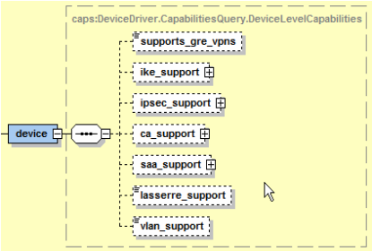
Each capabilities file defines a single set of device level capabilities, multiple groups of interface capabilities, and optionally a set of Service Application Points (SAP) capabilities.
Figure 7-4 describes the structure of the capabilities XML files generally take.
Figure 7-4 Example of the XML Structure of the Capabilities Files
Capabilities defined at the device level and are used to control what protocols and services a particular device is capable of supporting. It is important to note that even though a device may have the ability to support a feature set, the feature set may not be supported by the IOS currently installed on the device.
Here is an example of device level capabilities for SAA support under a Cisco device.
<caps:device>
   <caps:saa_support>
      <caps:operations_supported>1</caps:operations_supported>
      <caps:saa_types_support>15</caps:saa_types_support>
      <caps:netflow_version_support>7</caps:netflow_version_support>
   </caps:saa_support>
</caps:device>
At present, the supported capability types are SAA, Lasserre (TLS), and VLAN. To view the capabilities currently assigned to a device, right-click the device and select Properties, and select Capabilities from the side menu.
See the device capabilities reference table in "Capabilities classifications" for details on each device level capability.
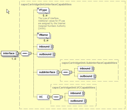
Interface inbound and outbound capabilities are defined for each main level interface, any sub-interfaces (optional), and any layer 2 VC capabilities (optional). Interface level capabilities do not provide further granularity to the supported device level capabilities. There is no relationship between device and interface level capabilities. Additionally, capabilities assigned to an interface bear no relationship to and do not restrict capabilities assigned to sub-interfaces and layer 2 interfaces. Figure 7-7 displays a visible example of these relationships.
To view the capabilities currently assigned to an interface right-click the interface, select Properties, and select Capabilities from the side menu.
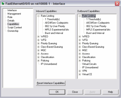
Figure 7-8 displays the interface capability dialog box.
Figure 7-8 Interface Capability Dialogue Box
Multiple interface types can share the same interface capabilities definition by declaring multiple ifType elements. Note that the ifType element is a standard SNMP MIB interface type as defined by the IANA. For more information on IANA ifType definitions please refer to the following URL: http://www.iana.org/assignments/ianaiftype-mib.
Note:
If no ifType is defined for a capabilities definition it is used as the default catch-all capability. Interface types that are discovered which are not currently referenced in the capabilities file receives this default capability. If no default capability is defined that will not receive capabilities.<caps:capabilities> … <caps:interface> <caps:ifType>17</caps:ifType><!--sdlc --> <caps:ifType>32</caps:ifType><!--FrameRelay --> <caps:ifType>77</caps:ifType><!--lapd--> <caps:ifType>171</caps:ifType><!-- POS --> <caps:inbound> … </caps:inbound> <caps:outbound> … </caps:outbound> … </caps:interface>
Service Application Points are used to model services that are not applied explicitly to an interface. SAP capabilities have a separate section of a capabilities definition that is not tied to the interface or device definitions. SAPs can be modeled and linked to a site and are used to represent configuration that resides on a device but is not explicitly assigned to an interface. When SAP capabilities are defined for a device/IOS combination, they restrict the type of configuration a user may apply to new or existing SAPs.
Each set of inbound and outbound capabilities definitions follow the same general structure for defining the inbound or outbound capabilities supported for the specific interface, sub-interface, VC, or SAP context.
Capabilities define the types of configurations hardware will support. Options however, are used to further refine how configuration is supported on a hardware and IOS combination.
Vendors with large numbers of hardware and software variants have allowed for non-standard configuration commands to exist. Options are a way of explicitly supporting a particular and often obscure command variant for a device or IOS. Additionally, you can create options to support IOS implementations that contain bugs or have unexpected behavior.
Additionally, there is often more than one way to apply a particular configuration to a router. Options allow the provider to implement a preferred method or standard of configuration.
For more information, refer to Options Framework in IP Service Activator Cisco IOS Cartridge Guide.
When you generate capabilities for a device, by default, all capabilities are open. If a configuration is provisioned that is not supported by a device/IOS/interface combination, the commands will fail for the device. The capabilities file must be manually edited so that only the supported or desired features can be provisioned and sent to device.
Consider the following factors when determining the initial capabilities definition for a particular device:
The current routing configuration.
What configuration types the hardware supports.
What type of configuration you want to perform.
The type of configuration the IP Service Activator cartridge currently supports.
Known issues or bugs with ISO versions in use, that may limit or constrain allowable configurations.
To modify or create the capabilities files:
Modify the capabilities file (or create a new capabilities file to modify).
If it is a new capabilities file, update the registry to reference the appropriate capabilities file. Reload the registry using the npAdmin.sh tool.
Un-manage the device.
Right-click the device, select Properties > Capabilities > Reset Device Capabilities and commit. This resets the capabilities of the device or interface.
Right-click the device and select Discover (or, Discovery > Fetch Capabilities; for the whole subnet).
Re-manage the device.
Note that, if an update is limited to the capabilities file, you do not need to reload the registry.
There are three ways of disabling capabilities in a capabilities file. You can disable capabilities by commenting out the element in the capabilities file using an XML comment. Alternatively, you can delete a specific capability element from the document. Finally, many capabilities can be disabled by setting their value from 1 to 0. You can also enable capabilities by setting their value from 0 to 1. It is important to ensure that when a capabilities file is edited that it still conforms to the capabilities schema and follows correct XML formatting.
Here is an example of an XML comment:
<caps:device>
<!-- <caps:saa_support>
<caps:operations_supported>1</caps:operations_supported>
<caps:saa_types_support>15</caps:saa_types_support>
<caps:netflow_version_support>7</caps:netflow_version_support>
</caps:saa_support> -->
</caps:device>
Here is an example of enabling/disabling priority queuing - pq:
<caps:pq>
<caps:support>0</caps:support>
<caps:classification>
<caps:supported>SRC_IP</caps:supported>
<caps:supported>DST_IP</caps:supported>
<caps:supported>SRC_PORT</caps:supported>
<caps:supported>DST_PORT</caps:supported>
<caps:supported>DIFFSERV</caps:supported>
<caps:supported>IPv4PRECEDENCE</caps:supported>
<caps:supported>IPv4TOS</caps:supported>
<caps:supported>URL</caps:supported>
<caps:supported>MIME</caps:supported>
<caps:supported>APP_PROTO</caps:supported>
<caps:supported>APP_NAME</caps:supported>
<caps:supported>DOMAIN_NAME</caps:supported>
<caps:supported>IEEE_802_1_PBITS</caps:supported>
<caps:supported>MPLS_EXP</caps:supported>
<caps:supported>MPLS_TOPMOST</caps:supported>
<caps:supported>CLASS_MAP</caps:supported>
<caps:supported>MATCH_ANY</caps:supported>
<caps:supported>ALCATEL_INTERNAL_QUEUE</caps:supported>
<caps:supported>TCP_HEADER_OPTIONS</caps:supported>
<caps:supported>TCP_ESTABLISHED</caps:supported>
<caps:supported>EXCLUDE_CLASSIFICATION</caps:supported>
<caps:supported>ICMP_HEADER_OPTIONS</caps:supported>
</caps:classification>
</caps:pq>
Once you define a capability set for a particular interface type, you can add new interfaces to the set. To do this, add the new interface type number to the appropriate caps definition in the Capabilities.xml file. For more information, refer to "Re-initializing Capabilities for a Device or Interface" and "Interface Capabilities".
Another common scenario is to create restricted capabilities for a specific device type or OS version to prevent the user from attempting to provision service configurations that the device does not support. To perform this restriction, create a new capabilities file by copying the existing open capabilities file and rename it. The name should represent the device type of IOS the file you intend to restrict. Edit the file as necessary and reference the file in the Mipsa_Registry.xml file. Restart the network processor to initialize the new set of capabilities. The capabilities sometimes affect a previously discovered device. For more information about how to deal with this situation, refer to "Re-initializing Capabilities for a Device or Interface".
These messages appear in the capabilities dialogue when a fetch does not occur or it is not successful. These are the two messages that you may see:
No specific capabilities reported: implies that there is no capability defined in the capabilities file for the device or interface. The device is discovered but the network processor is unable to match a specific capability to the hardware.
Capabilities not obtained: implies that the device of an unknown type is discovered. No device representing the device type/IOS combination is defined in the MIPSA_Registry.xml file. This can also occur if a device is unreachable or the wrong username or password is defined for the device during discovery.
To reset the capabilities for a device or interface:
Right-click the device, select Unmanage and commit.
Right-click the device and select Properties.
Select Capabilities in the Properties dialogue
Click Reset Device/Interface Capabilities in the Capabilities dialog and commit.
Rediscover the device to apply the new capabilities set to the device and interfaces.
Note:
Warning messages should be checked to ensure that the new capabilities match the current configuration or when a device is re-managed configuration may be stripped from the router.Not all devices support all the capabilities. In this case, if you push a configuration to a device that the device does not support; the device rejects it and causes a configuration rollback. If a particular a cartridge does not support a capability, and error message appears indicating that the configuration sent to the router resulted in no commands.
Note:
You must stop the network processor and restart it to pick up any capabilities file changes.This section details the capabilities presently supported by IP Service Activator. Here are the definitions of the parameters used in the tables below:
Boolean: of 0 or 1. The Value 1 indicates that the capability is supported.
Integer: any whole number. When set to 0, indicates the capability is not supported.
Additive: an integer value representing a bitmap. Values are added (bitwise AND operation) together to arrive at a supported set. For example, in the set
1 = UBR
2 = CBT
4 = RTVBR
8 = NRTVBR
16 = ABR
enabling UBR and CBT would mean setting a value of 3.
Table 7-3 lists the supported device capability element, and type.
Table 7-3 Device Capability Element Definitions
| Element | Type/Description | Supported |
|---|---|---|
|
<caps:ca_support> |
Boolean |
Yes |
|
<caps:supports_ca> |
Boolean |
Yes |
|
<caps:supports_ca_trusted_roots> |
Boolean |
Yes |
|
<caps:saa_support> |
Boolean Container for Service Assurance Agent capabilities supported by the device |
Yes |
|
<caps:operations_supported> |
Boolean Service Assurance Agent operations (probes) supported |
Yes |
|
<caps:saa_types_supported> |
Integer Supported SAA probe types. Bitfield addition of 1 = ICMP Echo 2 = TCP Connect 4 = UDP Echo 8 = Jitter |
Yes |
|
<caps:netflow_version_support> |
Integer Supported Netflow versions. Bitfield addition of 1 = Netflow V1 2 = Netflow V5 4 = Netflow V8 |
Yes |
|
<caps:lasserre_support> |
Boolean Lasserre (TLS or VPLS) supported by the device |
Yes |
|
<caps:vlan_support> |
Boolean Virtual LAN supported by the device |
Yes |
Table 7-4 lists and describes the interface capability element, and type.
Table 7-4 Interface Capability Element Definitions
| Element | Type/Description |
|---|---|
|
<caps:qos_mechanism_support> |
Container for QoS capabilities supported |
|
<caps:rate_limiting> |
Capabilities supported for Rate Limiting |
|
<caps:supports_burst> |
Boolean Rate Limiting supports Burst Rate and Burst Interval. 1=on, 0=off |
|
<caps:rate_limit_support> |
Container for Rate Limit supported |
|
<caps:support> |
Integer Number of PHBs that can be installed. 0=not supported |
|
<caps:classification> |
Container for Classifications supported. |
|
<caps:supported> |
Traffic classification types supported. See "Capabilities classifications". |
|
<caps:wred> |
Capabilities supported for Weighted Random Early Detection. |
|
<caps:support> |
Integer Number of PHBs that can be installed. 0=not supported. |
|
<caps:classification> |
Container for Classifications supported. |
|
<caps:supported> |
Traffic classification types supported. See "Capabilities classifications". |
|
<caps:wred_ecn> |
Boolean Weighted Random Early Detection with Explicit Congestion Notification supported. |
|
<caps:wfq> |
Capabilities supported for Weighted Fair Queuing. |
|
<caps:supports_high_priority_percent> |
Boolean Supports High Priority Percent. |
|
<caps:supports_low_priority_percent> |
Boolean Supports Low Priority Percent. |
|
<caps:wred_support> |
Container for Weighted Random Early Detection supported. |
|
<caps:support> |
Integer Number of PHBs that can be installed. 0=not supported. |
|
<caps:classification> |
Container for Classifications supported. |
|
<caps:supported> |
Traffic classification types supported. See "Capabilities classifications". |
|
<caps:wfq_support> |
Container for Weighted Fair Queue supported. |
|
<caps:support> |
Integer Number of PHBs that can be installed. 0=not supported. |
|
<caps:classification> |
Container for Classifications supported. |
|
<caps:supported> |
Traffic classification types supported. See "Capabilities classifications". |
|
<caps:supports_fr_de> |
Boolean Supports Frame Relay Discard Eligibility. |
|
<caps:wrr> |
Capabilities supported for Weighted Round Robin. |
|
<caps:support> |
Integer Number of PHBs that can be installed. 0=not supported. |
|
<caps:classification> |
Container for Classifications supported. |
|
<caps:supported> |
Traffic classification types supported. See "Capabilities classifications". |
|
<caps:pq> |
Capabilities supported for Priority Queuing. |
|
<caps:support> |
Integer Number of PHBs that can be installed. 0=not supported. |
|
<caps:classification> |
Container for Classifications supported. |
|
<caps:supported> |
Traffic classification types supported. See "Capabilities classifications". |
|
<caps:cbq> |
Capabilities supported for Class Based Queuing. |
|
<caps:support> |
Integer Number of PHBs that can be installed. 0=not supported. |
|
<caps:classification> |
Container for Classifications supported. |
|
<caps:supported> |
Traffic classification types supported. See "Capabilities classifications". |
|
<caps:frts> |
Capabilities supported for Frame Relay Traffic Shaping. |
|
<caps:supported> |
Boolean Frame Relay Traffic Shaping supported. |
|
<caps:becn_adapt> |
Boolean Backward Explicit Congestion Notification supported. |
|
<caps:fecn_adapt> |
Boolean Forward Explicit Congestion Notification supported. |
|
<caps:frf12> |
Boolean Frame Relay Fragmentation 12 supported. |
|
<caps:atmqos> |
Integer Supported ATM traffic types. Bitfield addition of: 1 = UBR 2 = CBT 4 = RTVBR 8 = NRTVBR 16 = ABR |
|
<caps:mqc> |
Capabilities supported for Modular QoS CLI. |
|
<caps:support> |
Integer Number of PHBs that can be installed. 0=not supported. |
|
<caps:classification> |
Container for Classifications supported. |
|
<caps:supported> |
Traffic classification types supported. See "Capabilities classifications". |
|
<caps:llq> |
Boolean Low Latency Queuing supported. |
|
<caps:llq_bandwidth_type> |
Integer LLQ bandwidth types supported. Bitfield addition of: 1 = Absolute 2 = Percentage 4 = Remaining Percent 8 = Default |
|
<caps:cbwfq> |
Boolean Class Based Weighted Fair Queuing supported. |
|
<caps:cbwfq_bandwidth_type> |
Integer CBWFQ bandwidth types supported. Bitfield addition of: 1 = Absolute 2 = Percentage 4 = Remaining Percent 8 = Default |
|
<caps:cbwfq_flow_queue_limit> |
Boolean Class Based Weighted Fair Queuing supports queuing limits. |
|
<caps:queue_limit> |
Boolean Queue Limit supported. |
|
<caps:single_rate_police> |
Boolean Single Rate Policing supported. |
|
<caps:policing_rate_type> |
Integer Policing bandwidth types supported. Bitfield addition of: 1 = Absolute 2 = Percentage 4 = Remaining Percent 8 = Default |
|
<caps:single_rate_police_action> |
Container for Single Rate Policing supported. |
|
<caps:supported> |
Traffic classification types supported. See "Capabilities classifications". |
|
<caps:aggregate_policer> |
Boolean Aggregate Policing supported. |
|
<caps:two_rate_police> |
Boolean Two Rate Policing supported. |
|
<caps:two_rate_police_action> |
Container for Two Rate Policing supported. |
|
<caps:supported> |
Traffic classification types supported. See "Capabilities classifications". |
|
<caps:shape> |
Boolean Shaping supported. |
|
<caps:shape_frts> |
Boolean Frame Relay Traffic Shaping supported. |
|
<caps:nest> |
Boolean Nesting supported. |
|
<caps:marking> |
Container for Packet Marking supported. |
|
<caps:supported> |
Traffic classification types supported. See "Capabilities classifications". |
|
<caps:wred_support> |
Container for Weighted Random Early Detection supported. |
|
<caps:support> |
Integer Number of PHBs that can be installed. 0=not supported. |
|
<caps:classification> |
Container for Classifications supported. |
|
<caps:supported> |
Traffic classification types supported. See "Capabilities classifications". |
|
<caps:rtp_tcp_header_compression_support> |
Boolean Real Time Protocol TCP Compression supported. |
|
<caps:wred_ecn> |
Boolean Weighted Random Early Detection with Explicit Congestion Notification supported. |
|
<caps:allowed_combinations> |
Container for supported QoS mechanisms. |
|
<caps:item> |
Integer Supported QoS mechanism combinations. Bitfield addition of: 1 = Rate Limit 2 = WRED 4 = WFQ 8 = WRR 16 = PQ 32 = CBQ 64 = FRTS 128 = ATM QoS Multiple <caps:item> elements can be defined to declare all supported combinations. |
|
<caps:service_rule_support> |
Container for all Service Rules supported. |
|
<caps:rules_supported> |
Integer Number of service rules that can be installed. 0=not supported |
|
<caps:mark_codepoints_supported> |
Container for Codepoints supported. |
|
<caps:supported> |
Traffic classification types supported. See "Capabilities classifications". |
|
<caps:limits_supported> |
Integer Number of limiting rules that can be installed. 0=not supported |
|
<caps:guarantees_supported> |
Integer Number of guarantees that can be installed. 0=not supported |
|
<caps:limits_and_guarantees_supported> |
Boolean |
|
<caps:classification> |
Container for Classifications supported. |
|
<caps:supported> |
Traffic classification types supported. See "Capabilities classifications". |
|
<caps:policing_rule_support> |
Container for Policing Rules supported. |
|
<caps:policing_supported> |
Integer Number of policing rules that can be installed. 0=not supported |
|
<caps:classification> |
Container for Classifications supported. |
|
<caps:supported> |
Traffic classification types supported. See "Capabilities classifications". |
|
<caps:classification_queues_supported> |
Integer Supported number of classification queues. Bitfield addition of: 1 = 1 COS queues 2 = 3 COS queues 4 = 8 COS queues |
|
<caps:mark_codepoints_supported> |
Container for Codepoints supported. |
|
<caps:supported> |
Traffic classification types supported. See "Capabilities classifications". |
|
<caps:access_rule_support> |
Container for Access Rules supported. |
|
<caps:access_rules_supported> |
Integer Number of access rules that can be installed. 0=not supported |
|
<caps:classification> |
Container for Classifications supported. |
|
<caps:supported> |
Traffic classification types supported. See "Capabilities classifications". |
|
<caps:all_mechanisms_combinations> |
Container for QoS mechanisms supported. |
|
<caps:item> |
Integer Supported QoS mechanism combinations. Bitfield addition of: 1 = Rate Limit 2 = WRED 4 = WRR 8 = WFQ 16 = PQ 32 = CBQ 64 = Mark only service rules 128 = Class Queues service rules 256 = N Queues service rules 512 = Policing rules 1024 = Access rules 2048 = VPN 4096 = FRTS 8192 = ATM QoS Multiple <caps:item> elements can be defined to declare all supported combinations. |
|
<caps:vc_support> |
Boolean Virtual Circuit supported. |
|
<caps:vpn_support> |
Container for Virtual Private Networks supported. |
|
<caps:supports_label_switching> |
Boolean Supports LSP based MPLS VPNs. |
|
<caps:supports_mpls_vpns> |
Boolean Interface supports MPLS VPNs. |
|
<caps:supports_RIP> |
Boolean RIP support for PE to CE routing protocol in MPLS VPNs. |
|
<caps:supports_static> |
Boolean Static route support for PE in MPLS VPNs. |
|
<caps:supports_OSPF> |
Boolean OSPF support for PE to CE routing protocol in MPLS VPNs. |
|
<caps:supports_eBGP> |
Boolean eBGP support for PE to CE routing protocol in MPLS VPNs. |
|
<caps:supports_EIGRP> |
Boolean EIGRP support for PE to CE routing protocol in MPLS VPNs. |
|
<caps:supports_dhcp> |
Boolean DHCP-Relay on VPN interface support. |
|
<caps:vce_support> |
Container for Virtual Circuit Endpoint supported. |
|
<caps:supports_virtual_ce> |
Boolean Interface supports Virtual CE service. |
|
<caps:supports_RIP_virtual_ce> |
Boolean RIP support for interface in Virtual CE. |
|
<caps:supports_static_virtual_ce> |
Boolean Static route creation support for interface in Virtual CE. |
|
<caps:supports_OSPF_virtual_ce> |
Boolean OSPF support for interface in Virtual CE. |
|
<caps:supports_eBGP_virtual_ce> |
Boolean eBGP support for interface in Virtual CE. |
|
<caps:supports_EIGRP_virtual_ce> |
Boolean EIGRP support for interface in Virtual CE. |
|
<caps:point_2_point_support> |
Container for Point to Point supported. |
|
<caps:ccc> |
Boolean Circuit cross connect supported (only on Juniper devices) |
|
<caps:martini_on_main_interface> |
Boolean Martini service on main interface supported. |
|
<caps:martini_on_sub_interface> |
Boolean Martini service on sub-interface supported. |
|
<caps:encapsulation> |
Integer Supported encapsulations. Bitfield addition of: 1 = PPP 2 = HDLC 4 = ATM AAL5 8 = ATM Cell 16 = Frame 32 = Ethernet 64 = Ethernet VLAN |
|
<caps:fr_vc_creation_support> |
Boolean Frame Relay VC creation supported. |
|
<caps:ip_unnumbered_support> |
Boolean IP unnumbered supported. |
|
<caps:capability_value_pairs> |
Container for Capability Value Pair supported. |
|
<caps:item> |
Supported items. Multiple <caps:item> elements can be defined to declare all supported capabilities. |
|
<caps:capability_type> |
Capability type. See "Capability value pairs". |
|
<caps:value> |
Value depends on the specific capability type declared. See "Capability value pairs". |
In the following example the SRC_IP classification is used. Table 7-5 lists and describes all other capabilities classifications.
<caps:classification>
<caps:supported>SRC_IP</caps:supported>
<caps:supported>DST_IP</caps:supported>
</caps:classification>
Table 7-5 Capabilities Classifications
| Classifications | Description |
|---|---|
|
SRC_IP |
Source IPv4 Address |
|
SRC_IPV6 |
Source IPv6 Address |
|
DST_IP |
Destination IPv4 Address |
|
DST_IPV6 |
Destination IPv6 Address |
|
SRC_PORT |
Source Port |
|
DST_PORT |
Destination Port |
|
IP_PROTO |
IP Protocol |
|
DIFFSERV |
Diff Serv |
|
IPV6_DIFFSERV |
IPv6 Diff Serv |
|
IPv4PRECEDENCE |
IPv4 Precedence |
|
IPV6_PRECEDENCE |
IPv6 Precedence |
|
IPv4TOS |
IPv4 TOS |
|
URL |
URL |
|
MIME |
MIME Type |
|
APP_PROTO |
Application Protocol |
|
APP_NAME |
Application Name |
|
DOMAIN_NAME |
Domain Name |
|
IEEE_802_1_PBITS |
802.1 PBits |
|
MPLS_EXP |
MPLS Experimental |
|
MPLS_TOPMOST |
MPLS Experimental Topmost |
|
CLASS_MAP |
Class Map |
|
MATCH_ANY |
Match Any |
|
ALCATEL_INTERNAL_QUEUE |
Alcatel Internal Queue |
|
TCP_HEADER_OPTIONS |
TCP Header Options |
|
TCP_ESTABLISHED |
TCP Established |
|
EXCLUDE_CLASSIFICATION |
Exclude Classification |
|
ICMP_HEADER_OPTIONS |
ICMP Header Options |
In the following example the MAX_RESERVED_BANDWIDTH capability is used. Table 7-6 lists and describes all of the capability value pair types.
<caps:item>
<caps:capability_type>MAX_RESERVED_BANDWIDTH<caps:capability_type>
<caps:value>1<caps:value>
</caps:item>
Table 7-6 Capability Value Pairs
| Capability Types | Type/Description |
|---|---|
|
MAX_RESERVED_BANDWIDTH |
Boolean When used in CapabilityTypeValuePair, the value corresponding to Maximum Reserved Bandwidth is a boolean to indicate whether it is supported. |
|
FRTS_INBOUND |
Boolean When used in CapabilityTypeValuePair, the value corresponding to FRTS Inbound is a boolean to indicate whether it is supported. |
|
LLQ_BURST_RATE |
Boolean When used in CapabilityTypeValuePair, the value corresponding to LLQ Burst Rate is a boolean to indicate whether it is supported. |
|
FRAME_RELAY_QUEUE_DEPTH |
Boolean When used in CapabilityTypeValuePair, the value corresponding to Frame Relay Queue Depth is a boolean to indicate whether it is supported. |
|
ATM_QUEUE_DEPTH |
Boolean When used in CapabilityTypeValuePair, the value corresponding to ATM Queue Depth is a boolean to indicate whether it is supported. |
|
ATM_TRANSMIT_RING_LIMIT |
Boolean When used in CapabilityTypeValuePair, the value corresponding to ATM Transmit Ring Buffer Limit is a boolean to indicate whether it is supported. |
|
SHAPING_BUFFERS |
Boolean When used in CapabilityTypeValuePair, the value corresponding to Shaping Buffers is a boolean to indicate whether it is supported. |
|
Copyright © 2011, 2013, Oracle and/or its affiliates. All rights reserved. Legal Notices |
|