| Oracle® Communications IP Service Activator System Administrator's Guide Release 7.2 E39366-01 |
|
|
PDF · Mobi · ePub |
| Oracle® Communications IP Service Activator System Administrator's Guide Release 7.2 E39366-01 |
|
|
PDF · Mobi · ePub |
This chapter describes verification and setup tasks you may need to perform after installation is completed and you have started Oracle Communications IP Service Activator.
This section provides the following procedures:
For information about automatically generating options and registry files for Cisco devices, see the Cisco Cartridge Configuration Utility section in IP Service Activator Cisco IOS Cartridge Guide.
The IP Service Activator GUI is adapted to display the Network Processor as a Proxy Agent under the domain. The Network Processor name in the GUI is proxy-np-host_name, for example: proxy-np-srvotlab481. This procedure verifies that the Network Processor is correctly assigned as a Proxy Agent for the domain.
Pre-requisites: The Network Processor is installed and verified. The Domain is created in the GUI.
If you recently restarted the Network Processor, you may have to wait a minute for the GUI screen to register the Network Processor restart. (You can force the GUI update using the main menu command: Tools, Find System Components.) A blue message in the fault pane indicates that the Network Processor is running.
To assign the Network Processor as a Proxy Agent:
Log into the GUI.
Review the Domain dialog box. On the Proxy Agent property page, identify the proxy-np-host_name object, where host_name is the name of the host.
Verify that the Network Processor is installed on that host.
When it appears in the Proxy Agent dialog box, the Network Processor is confirmed as a registered component in the IP Service Activator object model.
Verify that the following check box is selected.
proxy-np-proxy_agent
where proxy_agent is the name of the proxy agent.
If not, select the check box, as shown in the following image.
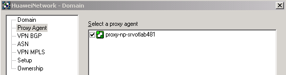
When the check box is selected, it confirms the Network Processor assignment as a Proxy Agent for that domain.
This section describes how to verify that cartridge installation was successful. Two approaches include:
The cartridge appears in the GUI after the Network Processor registers the cartridge in the object model.
To view the cartridge in the GUI:
Click the System tab and view the master_server objects in the Hierarchy pane.
You can see the Network Processor listed under the master_server (for example, proxy-np-servotlab481) and the cartridge listed in the Drivers folder (for example, huawei-np-srvotlab481). Discovered devices are listed last.
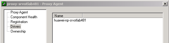
Right-click the Network Processor and select Properties.
The Proxy Agent dialog box for the Network Processor opens. On the Drivers property page, note that the cartridge is listed on the right (for example, huawei-np-srvotlab481).
Layer 2 Martini is supported through the vendor Cisco IOS cartridge and should be enabled only when required.
To enable Layer 2 Martini support:
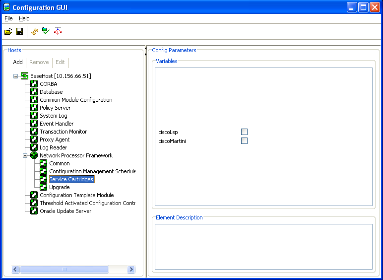
Log in to the Configuration GUI.
Under the component Network Processor Framework, select Service Cartridges.
A list of cartridges is displayed in the Config Parameters panel on the right.
Select the ciscoMartini check box.
Layer 2 Martini support is enabled.
Cartridge connectivity to a device is verified if you can discover the device.
To discover a device:
On the Global Setup screen, view the Domains tab.
Double-click the network icon in the Hierarchy pane.
The network screen appears.
On the Topology tab, select the network in the Hierarchy pane.
On the main menu, select Discovery, and then select Discover.
The Topology - Discovery dialog box appears.
On the Discovery property page, enter the DNS name or IP address of the device that you want to discover, and then select the Add button.
On the Security property page, select the Access style (for example, select TACACS+ for Huawei devices).
Select OK.
On the Topology tab, double-click the network cloud to see the discovered device.
Each discovered device is listed under the network cloud. The device also appears in the Details pane, on the Network_Name tab.
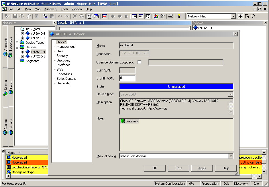
Right-click the device and select Properties.
The Device dialog box appears.
The Device property page lists the type and a description of the discovered device.
After you successfully install IP Service Activator, log into the IP Service Activator GUI and confirm the router configurations to ensure that they are set up correctly to work with the system.
Check that device communication protocols are enabled.
Check that the SNMP and device security settings match the target device.
Check that there are some numbered access control lists (ACLs) free for use by IP Service Activator between the following ranges:
100 to 199 for all Cisco devices and
2000 to 2699 for Cisco devices that support the expanded range of ACLs.
The number of free ACLs required by IP Service Activator is dependent on the number of policy rules and QoS mechanisms you want to apply to an interface.
Check that ACLs restricting Telnet allow access from all Proxy Agents, the Policy Server and user interface hosts.
Check that any ACLs restricting SNMP access to the router will allow access from all Proxy Agents and the Policy Server.
Check whether there are any existing Custom Queuing, WRED, WFQ, GTS, or queue lists operating on interfaces where policy is to be applied. The IP Service Activator system does not overwrite any pre-existing configuration with new configuration details if they conflict.
Check whether there are route maps operating on interfaces where policy is to be applied. IP Service Activator does not update an existing route map. If you require these route maps for non-QoS purposes, you may want to use CAR-based marking on IOS 12.0 or later.
Check that firewall filters restricting Telnet or SSH allow access from all Proxy Agents, the Policy Server and user interface hosts.
Check that the user specified in IP Service Activator's device security settings has access privileges that permit interface and routing configuration.
At the system or (active) groups configuration hierarchy level, check whether there is any configuration operating on interfaces where policy is to be applied that might potentially conflict with the planned provisioning commands generated by IP Service Activator. In particular, check that there are no input or output firewall filters, VRFs, Layer 2 circuits, cross-connects and/or PHB Groups already configured on those interfaces.
IP Service Activator detects incompatibilities in physical interface encapsulation pre-existing on the router when the Device Driver is building a new configuration for CCCs and/or Layer 2 circuits. An error is displayed in the UI and the user has an option to manually correct the interface encapsulation. In order to expedite the configuration process, ensure that proper interface encapsulations are provisioned as per Juniper (Junos) documentation.
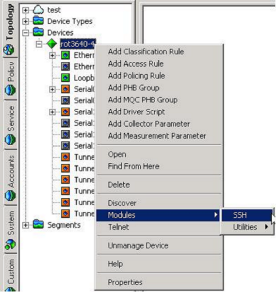
Secure Shell (SSH) is a UNIX-based command interface and protocol for securely accessing a remote computer. SSH commands are encrypted and both ends of the client/server connection are authenticated using a digital certificate.
To run this utility, the following applications are required:
Oracle Database is installed on a Solaris/Linux machine, and a database instance is created.
IP Service Activator server software is installed on a Solaris/Linux machine.
IP Service Activator GUI client software is installed on a Windows 7.0 or Windows XP Professional workstation.
An SSH client is installed on a Windows GUI workstation.
For client communication with a device, the SSH protocol must be enabled on the device.
For best results in the graphical user interface (GUI), it is recommended to run IP Service Activator modules and utilities at a minimum screen resolution of 1024 by 768 pixels.
The default executable for the SSH module as listed in script commands in ExplorerScripts.xml is SSH.exe. However, you must provide an actual SSH application and update the ExplorerScripts.xml file accordingly, replacing SSH.exe with the name of the actual SSH application you are implementing.
For example, as shipped, the ExplorerScripts.xml file specifies ssh.exe:
<Script command=""C:\Program Files\Oracle Communications\IP Service Activator/ExplorerScripts/launcher.bat" eeucommon.jar com.mslv.osa.custom.executable.LaunchExec %1 %2 %3 %4 %5 start ssh.exe" name="SSH" objects="Device"></Script>
You must update this line to reflect the actual SSH application that you are implementing. If using putty, you would change this line to read:
<Script command=""C:\Program Files\Oracle Communications\IP Service Activator/ExplorerScripts/launcher.bat" eeucommon.jar com.mslv.osa.custom.executable.LaunchExec %1 %2 %3 %4 %5 start c:\putty.exe" name="SSH" objects="Device"></Script>
A large number of ready-to-use configuration policies are provided with IP Service Activator and can be used as-is for various purposes.
(Alternatively, you can use the IP Service Activator SDK to create and customize configuration policies as well as a service cartridge to support the implementation of the services that the configuration policy provides.)
The configuration policy files shipped with IP Service Activator are installed to the hard drive of the target machine Oracle Universal Installer.
To use the configuration policies, they must be loaded into your IP Service Activator installation through the GUI.
Only users belonging to the Read Write and Super User groups can view and use configuration policies through the GUI. See "Setting Up Users and Menus" for more information.
Refer to the chapter on configuration policies in IP Service Activator QoS User's Guide for more details about using configuration policies to extend the capabilities of IP Service Activator.
For detailed information about particular configuration policies, including descriptions of all fields and ranges supported on the HTML input screen, see IP Service Activator online Help.
The configuration policy files included with IP Service Activator are installed to the target machine by Oracle Universal Installer during the installation of IP Service Activator.
To apply configuration policies, they must be loaded into an IP Service Activator domain in the following order:
default.policy
advanced.policy
Rule_and_PHB.policy
Note:
Do not load Rule_and_PHB.policy if you have already created standard PHB groups.Table 2-1 lists the configuration policy files and their description:
Table 2-1 Configuration Policy File Descriptions
| Filename (.policy file) | Description |
|---|---|
|
advanced.policy |
This file contains additional definitions for:
Note: Load default.policy before loading this file. |
|
AlcatelSAMPolicyTypes.policy |
This file contains standard definitions for the following configuration policies:
Note: Alcatel Layer 3 Interface is loaded under the Interface sub-folder in the Policy Types folder. |
|
CiscoCatOSQoSPolicyTypes.policy |
This file contains standard definitions for the following configuration policy:
|
|
CiscoIOSQoSPolicyTypes.policy |
This file contains standard definitions for the following configuration policies:
|
|
ConfigletPolicyTypes.policy |
This file contains standard definitions for the following configuration policy:
This is a special policy type that does not include HTML. You cannot use this like other configuration policies by directly applying it on a policy target. Note: You must load this policy before you use Configuration Template Module (CTM). |
|
ConfigurationManagementPolicyTypes.policy |
This file contains standard definitions for the following configuration policies:
This is a special policy type that does not include HTML Archive Schedule. |
|
default.policy |
This file contains standard definitions for:
Note:
|
|
default.dscp.policy |
This file contains standard definitions for:
This variant of default.policy is compatible with IP Service Activator releases prior to 5.1.3. It may be more appropriate when not using the Network Processor. Packet marking policies use DSCP values, instead of IP Precedence values. Note: Do not load this policy file into a domain that has the new default.policy file. |
|
ExtensionPackAPolicyTypes.policy |
This file contains standard definitions for the following configuration policies:
|
|
ExtensionPackBPolicyTypes.policy |
This file contains standard definitions for the following configuration policies:
|
|
ExtensionPackCPolicyTypes.policy |
This file contains standard definitions for the following configuration policies:
|
|
FoundryIronWareQoSPolicyTypes.policy |
This file contains standard definitions for the Foundry Rate Limit configuration policy. |
|
GeneralPolicyTypes.policy |
This file contains standard definitions for the following configuration policies:
|
|
InterfaceManagementPolicyTypes.policy |
This file contains standard definitions for the following configuration policies:
Note: These policies are loaded under the Interface sub-folder in the Policy Types folder. |
|
ipsec.policy |
This file contains standard definitions for:
|
|
IPSecPolicyTypes.policy |
This file contains standard definitions for the following configuration policies:
|
|
juniper.policy |
This file contains CoS definitions and an example PHB definition that uses the default IP Service Activator's IP Precedence mapping. You must load this file if you are managing QoS on Juniper M-series devices. |
|
JuniperJUNOSQoSPolicyTypes.policy |
This file contains standard definitions for the Juniper JUNOS COS Attachment configuration policy. |
|
LSPPolicyTypes.policy |
This file contains standard definitions for the LSP Tunnel configuration policy. |
|
MulticastInterfacePolicyTypes.policy |
This file contains standard definitions for the Multicast Interface configuration policy to be used with VPN and IP Multicast Policy Type services. |
|
Role_Assignment_Rules.policy |
This file contains examples of role assignment rules. Note: Load default.policy before loading this file. |
|
RoutePolicyPolicyTypes.policy |
This file contains standard definitions for the following configuration policies:
|
|
Rule_and_PHB.policy |
This file contains examples of:
Note: Load default.policy and advanced.policy before loading this file. |
|
ServiceAssurancePolicyTypes.policy |
This file contains standard definitions for the following configuration policies:
|
|
SharedPolicyData.policy |
Load this file only to add the IPv6 protocols or replace any IPv4 or IPv6 protocols that have been removed accidentally. Note: Your system will automatically load this file. |
|
VLANPolicyTypes.policy |
This file contains standard definitions for the following configuration policies:
|
|
IPMulticastPolicyTypes.policy |
This file contains standard definitions for the following configuration policies:
Multicast Interface types can be installed by loading the MulticastInterfacePolicyTypes.policy file. |
|
VPNMulticastPolicyTypes.policy |
This file contains standard definitions for the Multicast VRF configuration policy. Multicast Interface types can be installed by loading the MulticastInterfacePolicyTypes.policy file. |
To load configuration policies into IP Service Activator:
On the Global Setup window, select a domain from the Hierarchy pane.
Right-click on the Domain and from the pop-up menu, select Properties.
On the Domain dialog box, select the Setup property page.
Click Browse.
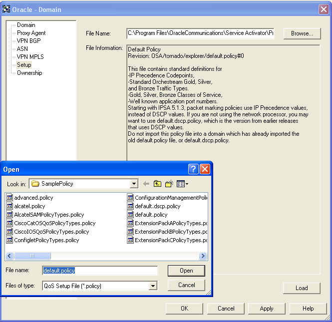
Select the .policy file you want to load, and click Open.
Click Load.
The configuration policy loads and a confirmation dialog is displayed.
Click OK to close the confirmation dialog.
Click OK to close the Domain dialog box.
Commit the transaction.
After it is loaded, the configuration policy is available to all GUI instances, since it is integrated into the object model inside the domain.
You can verify which configuration policies are loaded into IP Service Activator by selecting the Policy tab and inspecting the contents of the Policy Types folder.
You can add new configuration policies from their component files (HTML and schema) when no policy files are provided.
To load a configuration policy as a new Policy Type:
On the Global Setup window, double-click a Domain from the Hierarchy pane to open it.
Select the Policy tab.
Expand the Policy Types folder.
Explore the hierarchy and locate the sub-folder in which you want to load the configuration policy.
Right-click on the target folder and select Add Policy Type from the pop-up menu.
The Policy Types dialog is displayed.
In the Name field provide a name for the configuration policy.
In the Type field, provide the element type for the configuration policy as specified in the .xsd or as provided by the developers of the configuration policy.
This can be determined by inspecting the .xsd file and locating the main element name near the bottom of the file. For example, the Type for the banner configuration policy is shown as:
xs:element name="banners" type="bn:Banners"
Click Import HTML.
Select the HTML file for the configuration policy you are importing and click Open.
Click Import Schema.
Select the .xsd schema file for the configuration policy you are importing and click Open.
Click OK.
Commit the transaction.
The imported configuration policy now appears in the Policy Type hierarchy.
IP Service Activator can be used to import the .html and .xsd source files into a Policy Type and then export a loadable .policy file.
Exporting the files makes it simpler to deploy configuration policies, since the policy file can be easily loaded into a domain (see "Loading Configuration Policies"). After it is loaded, the configuration policy is available to all GUI instances, since it is integrated into the object model inside the domain.
To export a policy file:
Follow the steps in "Adding a Configuration Policy as a New Policy Type" if the Policy Type is not already created for the configuration policy.
In the Policy tab, under the Policy Types hierarchy, right-click on the source configuration policy and select Properties.
Click Export Policy.
Navigate to the location you want the .policy file written to, provide a name, and click Save.
Click OK.
Note:
The sub-folder hierarchy in place from which the source configuration policy is exported is used as the default installation location when the resultant .policy file is re-imported into the GUI.If you want to have the configuration policy loaded to a particular sub-folder, model that location and create the Policy Type there prior to export.
The Common module installation loads controller scripts that are used with various other modules to send commands to devices. Depending on which modules you have installed, you will have to import and link the appropriate controller scripts before running the modules.
Load the appropriate controller scripts for the device types in your network. You may skip any controller script for a device type which you are not implementing.
Table 2-2 Controller Scripts Required for the Modules
| Module (modules not listed do not require controller scripts) | Controller Scripts required |
|---|---|
|
MPLS LSP |
juniperM_controller.py |
|
Configuration Template |
juniperM_controller.py |
To import and link a controller script:
Log into the IP Service Activator GUI. Double-click the domain. From the Topology tab, right-click the network object and select Add Driver Script.
The Driver Script dialog box appears.
Select the Driver Script page.
Note:
A driver script can be loaded at device level, domain level, or network level. This script is required when using device drivers.Click Import and select the appropriate device_controller.py file.
Click OK.
Repeat this procedure for additional controller scripts that your modules require.
The configuration file AutoDiscovery.cfg, which contains information about the devices supported and specific configuration details, is used by the IP Service Activator system when discovering devices. This file is located in the Service_Activator_Home/Config folder. It consists of a number of directives, one per line. There is one line for each vendor supported, of the following syntax:
Enterprise:<enterprise_number>;<enterprise_name>;<device_driver>;<supported>;<access_type><config_level>;
The following table lists the parameters in the AutoDiscovery.cfg file for devices.
Table 2-3 Parameters in AutoDiscovery.cfg for Devices
| Parameter | Description |
|---|---|
|
enterprise_ number |
Registered enterprise number. For example, Cisco=9. |
|
enterprise_name |
This is a text string mentioning the enterprise name. |
|
device_driver |
Name of the device driver to use support products. |
|
supported |
Whether these devices are supported (yes or no). |
|
access_type |
Default access type (one of tacacs, nameduser, anonymous, or none). |
|
config_level |
Whether interface or device level configuration (one of device or interface). |
There is one line for each type of subinterface supported, of the following syntax:
Subinterface:<enterprise_number>;<higher_iftype>;<lower_iftype>;
The following table lists the parameters in AutoDiscovery.cfg for subinterfaces.
Table 2-4 Parameters in AutoDiscovery.cfg for Subinterfaces
| Parameter | Description |
|---|---|
|
enterprise_ number |
Registered enterprise number. For example, Cisco=9. |
|
higher_iftype |
Interface IfType for higher layer in stack. For example, FrameRelay (32). |
|
lower_iftype |
Interface IfType for lower layer in stack. For example, AtmSubInterface (134). |
A new line has been added for AutoDiscovery.cfg named RenameSysDescr. This can be used in the following manner:
RenameSysDescr:9;Engineering Special;;
In order for the Network Processor cartridge to allow proper parsing of the Version string sysdescr, and in order to infer the OS version, the Network Processor cartridge assumes that the Version keyword is the first one after a ”,” character.
For further information about AutoDiscovery.cfg, see the Customizing discovery using AutoDiscovery.cfg section in IP Service Activator User's Guide.
For information about how to enable discovery of dialer interfaces with PPP encapsulation on Cisco devices, see IP Service Activator Cisco IOS Cartridge Guide.
After installing IP Service Activator and before initial startup, do the following as appropriate.
"Permitting GUI Access to the Network Processor" (mandatory only if there is a firewall between the IP Service Activator GUI and the Network Processor): this opens the Network Processor port so the GUI can send device configuration audit results to the Network Processor.
Note:
On some Windows versions, such as Windows 7, Telnet is not installed by default. If it is not installed, you can install it by turning the Windows feature on.If you want to allow users to access Configuration Template Module (CTM) functionality, you can assign permissions to their IP Service Activator user groups. For more information, see "Allowing a User Group to Access Configuration Template Module" or see the information about Configuration Template Module in IP Service Activator online Help.
|
Copyright © 2011, 2013, Oracle and/or its affiliates. All rights reserved. Legal Notices |
|