| Oracle® Communications IP Service Activator Concepts Release 7.2 E47715-01 |
|
|
PDF · Mobi · ePub |
| Oracle® Communications IP Service Activator Concepts Release 7.2 E47715-01 |
|
|
PDF · Mobi · ePub |
This chapter describes the key features of Oracle Communications IP Service Activator.
Figure 2-1 illustrates the core IP Service Activator functions and features.
These aspects are discussed further in the following sections.
Figure 2-1 Core IP Service Activator Functions and Features
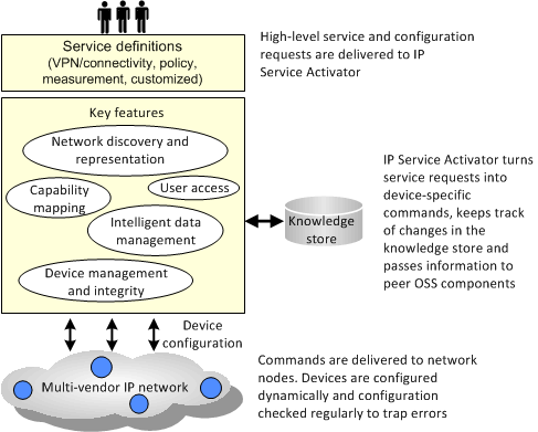
IP Service Activator incorporates a network discovery engine that is able to discover information about the physical network, including routers, interfaces and network segments, and create a detailed internal model.
The discovery process includes the following stages:
Discovering devices, segments, and hosts
Assigning devices to the components that are responsible for managing them
Assigning policy roles to devices and interfaces
Setting up the security and authentication parameters that IP Service Activator needs to configure devices
Ascertaining the capabilities of devices and interfaces – the VPN, QoS and measurement options that are available at each network node
Given a valid IP address or DNS name of a device in the network, IP Service Activator can retrieve details of the device, its interfaces, and any sub-interfaces and ATM or Frame Relay virtual circuit (VC) endpoints present. Connectivity information is also obtained from querying the routing table.
It is possible to enter a number of IP addresses or a subnet mask and discover multiple devices at once. In addition, if public IP addresses are used, it is possible to search for connected devices by specifying the number of hops to go from the initial device. In this way, it is possible to discover the entire network in one pass.
Note:
You can use a subnet mask only for discovery using IPv4, not for discovery using IPv6.If any changes are made to the network configuration at any time, the discovery process can be re-run. You can either update the entire domain, or rediscover a single device.
The discovery process can also be set up to run automatically on a regular basis to ensure that the network topology is kept up-to-date. For example, you can configure IP Service Activator to run device discovery as an overnight process.
For each device, appropriate security parameters, such as user IDs and passwords, must be specified to allow IP Service Activator to configure the device. This information need only be set up once.
The method used to communicate with the device depends on the options supported by the vendor and the level of security implemented in your network. SSH (Secure Shell) can be used to ensure secure communication between Device Drivers and routers. Access can be controlled by passwords or an RSA key file. On Cisco devices, IP Service Activator supports the use of a TACACS+ server for authenticating and authorizing access to devices.
If standard security information is set up prior to discovery it will be applied automatically to all discovered devices. This can save time if you use the same access methods and passwords for a number of devices in your network.
At the end of the discovery process, IP Service Activator determines the hardware and software versions of the device and then sets the capabilities of each discovered device accordingly.
Capabilities are set for each device and its interfaces, sub-interfaces and VC endpoints to precisely define the VPN, QoS, access control, and measurement options available. For interfaces and sub-interfaces, inbound and outbound capabilities are reported separately.
After discovery is complete, IP Service Activator updates its representation of the topology model in the Knowledge Store:
Networks: A network is a logical object only, representing all or part of the network to be managed. For each domain, a root-level network object is automatically created, which equates directly to the domain.
To simplify the management of large and complex networks, you can set up subsidiary networks, each with its own topology map. Depending on the complexity of the network, you can create a multi-level hierarchy of subsidiary networks.
Devices: Within IP Service Activator, a device can be defined as a network node that forwards IP packets, that is, a router or Layer 3 switch. Each device in the network is classified according to vendor type, which defines the Device Driver or Network Processor cartridge that will be used to manage the device. Note though, that it is possible to discover devices that cannot be managed.
It is possible to create a virtual device manually in the client to represent a device that IP Service Activator has not discovered. This means that devices not managed by IP Service Activator, such as those in the core network or in the customer's domain, can be modeled.
Interfaces and sub-interfaces: Interface and sub-interface objects represent the physical and logical interfaces on a device. This information is obtained from the interface table of the device during device discovery and the corresponding objects are created automatically.
PVCs: For ATM and Frame Relay interfaces, IP Service Activator looks for PVCs (Permanent Virtual Circuits) on the device and creates VC endpoints to represent them. These endpoints can be connected in the user interface to create a representation of the virtual circuit.
Segments: A segment object represents a locally-connected segment on an interface. Segments are classified according to type, for example, serial, bus or ATM cloud.
Hosts: A host can be defined as a network node that does not forward IP packets, for example, a PC, workstation, server or network printer. Hosts are found during the discovery process, and can be included for completeness although IP Service Activator does not manage them.
The hierarchical representation of the network topology appears in the Hierarchy pane on the client.
The managed network is displayed in the form of one or more topology maps on the client. As illustrated, the client provides a graphical and hierarchical representation of the managed network.
Figure 2-2 Hierarchical and Graphical Representation of the Network in the IP Service Activator Client
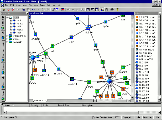
The options for producing maps are flexible, and each network can have a number of alternative map views. For example, you can have one map showing the entire network and additional maps illustrating different portions of the network, such as the specific geographical or management regions. Alternatively, one map could display the network devices and segments and another could display the device interfaces and sub-interfaces. VPNs and their connected sites can also be mapped.
If the network is subdivided into two or more network objects, you can create maps for each sub-network, and drag and drop objects between maps.
The scale of the map can be changed to enable you to see the entire map at once or zoom into a particular section in more detail.
Network topology maps can be set up manually, by dragging and dropping network objects from an on-screen palette. You can control the positioning of objects by snapping them to an invisible grid layout. Connections between objects appear automatically.
The objects that appear in the palette are relevant to the object currently selected. For example if you choose a device, those interfaces that are not currently mapped are listed in the palette. If you select an interface, unmapped sub-interfaces and segments are listed. This context-sensitivity can be turned off, in which case it is possible to select the types of objects to be listed.
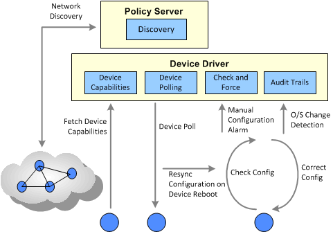
Figure 2-3 shows how IP Service Activator ensures device integrity.
Figure 2-3 Techniques for IP Service Activator Device Integrity
The Device Drivers and Network Processor are the IP Service Activator components that are responsible for configuring individual network elements. They convert the abstract expressions of services, which have been calculated and validated by the central server, into the commands required to configure each element.
The device configuration is updated by issuing commands via the command-line interface (CLI). Access can be authenticated in a number of ways, including as a named or anonymous user, through a TACACS+ server or through the SSH protocol.
IP Service Activator maintains the authentication information for all devices. If the same access and authentication methods are used throughout the network, the parameters can be set up before device discovery and are then applied to all devices. Where devices have unique passwords, they need to have their security parameters set up separately.
Rather than simply pushing commands out to each router, the Device Driver or Network Processor manages the configuration intelligently, ensuring that the required configuration is not affected by the device going down or someone else making changes to the configuration. It does this by using an internal model of the configuration of each managed device, comprising the services and policies that have been requested by users.
The Device Driver extracts the real configuration from the device and compares this with its internal model. If there are differences in the specific parts of the configuration that IP Service Activator configures, the configuration is updated. This comparison and update process is run every time the virtual configuration changes; that is, whenever any changes are made to requested services. If there is a mismatch, the configuration is updated.
The Device Drivers only ever reconfigure those interfaces that are specifically managed by IP Service Activator. If the requested configuration would conflict with essential routing and set-up configuration, it is not applied.
The Network Processor functions slightly differently than the Device Drivers. It does not read the configuration on the device. Instead, it calculates the new device configuration based on the current transaction and the last pushed state for the device as stored in persisted data.
IP Service Activator ensures that the configuration of each device is correctly maintained, even if the device goes down and configuration is lost.
At regular intervals, all the devices that are under the control of the Device Driver are polled by the proxy agent to check if they are still running.
If any router has re-booted since the last time it was checked, IP Service Activator automatically runs a resynchronization process. The current device configuration is extracted and compared with the virtual state. If there is a mismatch, the device is reconfigured.
Normally, no user action is required. Occasionally, manual intervention is needed before IP Service Activator is able to resynchronize, for example, in the case of a hardware or software re-configuration of a device. In this case, the device status is changed to Intervention Required.
You can set up IP Service Activator to co-exist with manually configured features, such as VRF tables and export maps.
Device Drivers can check for changes to device configuration that have been made manually by other users. Depending on a user-configurable option, a driver can force consistency of configuration automatically or issue a warning so that the device configuration can be investigated. The Network Processor does not force consistency.
Each installed Device Driver records all configuration changes that it makes to devices under its control. The log files can be examined to check the date, time, user and details of each configuration change applied to each device.
Errors occurring in devices can be reported as SNMP traps, allowing integration with other network management tools.
The way that IP Service Activator models and maintains data is fundamental to its operation.
IP Service Activator's knowledge store is a repository of all required information. This information falls into three inter-related groups, as illustrated in Figure 2-4:
Network topology data: a representation of the network being managed by IP Service Activator. This includes details of devices and their connectivity and the membership of VPNs.
Policy data: information relating to the policies and services that are used to configure the network.
System data: information about the IP Service Activator components and user details, including status, fault, and logging information.
Figure 2-4 Knowledge Store Information Groups
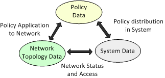
The knowledge store is also known as the object model: every element is modeled as an object instance of a pre-defined class. Each object has a set of attributes that identify it and hold its data, and associations that define its relationship to other objects.
The knowledge store is held in memory, but is mapped to a series of tables within the database for persistent storage. A simplified version of the knowledge store, known as the External Object Model (EOM), is available to external applications.
The External Object Model (EOM) is a simplified version of IP Service Activator's knowledge store. It defines all the objects that can be accessed or updated by external applications, including their attributes and the relationships between them.
Using a subset of the entire object model means that user programs can create and access data objects without needing to know the underlying complexity of the entire object model. The External Object Model is independent of the command syntax – new attributes and objects can be added without requiring new commands.
Objects in the External Object Model are divided into three major categories:
Topology: Represent the topology of the managed network, such as Network, Device and Interface objects.
Policy: Represent elements used to define policies and services that can be configured on network nodes, such as Domain, Rule and Traffic Type objects.
System: Represent IP Service Activator components and the event handler subscription model, such as Component, Subscription and Fault objects.
All changes made to the knowledge store are handled in the form of transactions. A transaction model allows users to exercise control over when and how changes take place. For example:
A set of configuration changes can be created and grouped together and stored in the database for later application.
Complex configuration changes can be broken down into a number of small transactions and applied incrementally.
Specific configuration changes can be scheduled to be applied at a specified time in the future.
A committed transaction may be rolled back to restore the device configuration to its previous state.
A transaction can consist of any sequence of operations, where an operation is one of the following:
Creating or deleting an object
Modifying an object's attributes
Linking or unlinking two objects
For example, a single transaction could consist of setting up a number of customer sites and linking them together to form a VPN.
As well as transactions performed by users, actions performed by IP Service Activator are recorded as transactions.
Details of each committed transaction are archived, including the user who created it, its status, timing details, and the operations it comprises.
Required changes can be broken down into a number of discrete transactions and implemented in a controlled manner. For example, a series of policy rules could be held in a number of transactions and their implementation phased over a period of time.
It is also possible to schedule a transaction so that it is applied at a specific date and time. For example, an operation to update the network could be applied at a time when traffic was at a minimum. At the appropriate time the transaction is automatically committed and the updates made.
Depending on the security permissions set up for specific users, different individuals or groups of users can have different access rights for managing transactions. For example, some users may be able to create transactions and save them, while the right to commit or schedule existing transactions may be restricted to supervisory staff.
There are two potential workflows for working with transactions:
One-stage commit model, where a user makes changes through the client and immediately commits the changes. For example, a super user might use this to set up additional users or basic data.
Two-stage commit model, where one user saves the changes as a transaction and another merges the transaction to check its changes and finally commits it. For example, an operator might set up a VPN and a supervisor could check the changes before committing the transaction. In this model, the user can also save the transaction, and it can be scheduled to later point of time to commit the transaction.
This two stage process is shown in Figure 2-5.
A committed transaction can be rolled back in order to undo a set of changes that have been made. When a transaction is rolled back, its changes are removed from the object model and any configuration installed on network devices is removed. Any committed transaction can be rolled back providing that the changes involved are still valid within the current object model.
The client almost always reflects the network as it is currently configured. The only point at which it does not reflect the current state is when you are creating a transaction. Once the transaction is saved, the client reverts to the true state of the network.
Access to IP Service Activator's powerful facilities for network configuration (through the client or from an external application through an API) can be controlled by extremely flexible security options. Security can be set up to control the following:
Access to the client
The operations a user can perform
The information users can see through the client or OSS Integration Manager (OIM)
User permissions on specific objects
The ownership of individual object instances
Every user must have a login name and password to access IP Service Activator. To ensure security, system administrators can specify a minimum length for passwords, set an expiry time for passwords and prevent password re-use. User accounts can be disabled after repeated log-in failure.
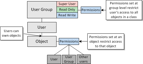
Each IP Service Activator user is allocated to a user group, which defines the functions the user can perform. Each user group can have one of the following access types:
Read Only: group members can view objects but not modify them
Read Write: group members may be able to view or modify objects
Super User: group members can view and modify all objects
For Read Write groups, you can set permissions which specify exactly which elements of IP Service Activator its members can view and modify. This enables you to limit access according to the role that users perform, or the customer accounts they are managing. Permissions can be set for the following:
Access permissions, (such as Read-only, Modify, Create) can be set for specific object classes (for example, a user can be set to have Modify access on all VPNs)
Specific operations (such as running a network discovery operation) can be permitted or denied
A user's access level can affect the appearance of the client. Objects that a user does not have permission to see do not appear.
For fine-grained control of security, it is possible to control access to specific object instances. Permissions can be set that apply to the owning user, the group to which the user belongs and all other users.
Figure 2-6 Object Ownership and Permission Levels
